AD PCB布局拖动元器件时出现的红线、绿线(Optimal Placement Vector)
文章目录
- 问题
- 设置
- 操作
- 详解
问题

初学AD,看到很多PCB布局拖动元器件时会显示红线、绿线,但在我自己操作界面拖动时没有红、绿线显示。应该是设置的问题,那该怎样隐藏和显示红、绿线呢?于是网上各种找,但找到的都是提出的同样问题或者感性分析,问题并没有得到实际的解决,找了半天,接近放弃的边缘。第二天抱着试试的态度,又重新找了找,找到了答案,现在分享给大家。觉得有用请点赞,哈哈哈。
设置
Preferences→System→General→Advanced Settings→PCB.ComponentDrag.ShowAverageHelper
操作
勾选或取消掉对应value的单选框即可打开或关闭PCB布局中出现的红线、绿线。

详解
Component Positioning Guide
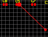
As you move a component around in the workspace, a thick green or red line will be displayed, traveling from a point within the component, to a location on the board. This line is called the Optimal Placement Vector, its function is to give an indication of whether the new location is better (green) or worse (red) than the previous location.
The vector has two distinct properties: its proposed target location; and its color.
To determine the locations for each end of the vector, the feature uses the centroid of the polygonal shape defined by the locations of the end points of the connection lines. There are two centroids of interest, one defined by the ends of the connection lines terminating on the component you are moving (the component centroid), the second defined by the other ends of that set of connection lines (the target location centroid).
The Optimal Placement Vector is drawn between these two centroids, with the component end highlighted by a dot. Because it is a relative indicator, when you first click to start moving a component the vector is always drawn in green. The two centroids are continuously re-calculated as you move the component, because the connection lines can move from one pad to another as they are automatically re-optimized to maintain the applicable net topology for the moving component. Because of this net re-optimization, the target end of the OPV can jump around as the component is moved. If the centroids move apart and the OPV becomes longer, it may change to red. If the centroids move closer together and the OPV becomes shorter, it may change to green.
The length of the vector is not the only condition used to set the color, the color of the OPV is also affected by the overall length of the connection lines attached to the moving component. If moving the component results in the overall length of the connection lines increasing, then the OPV becomes red. Alternatively, if moving the component results in the overall length of the connection lines decreasing, then it becomes green.
