OpenCV学习笔记(5):绘制图形:直线、矩形、圆、椭圆、多边形
OpenCV学习笔记(5):绘制图形:直线、矩形、圆、椭圆、多边形
目录
- OpenCV学习笔记(5):绘制图形:直线、矩形、圆、椭圆、多边形
- 01 绘制直线 cv2.line
- 02 绘制矩形 cv2.rectangle
- 03 绘制圆 cv2.circle
- 04 绘制椭圆 cv2.ellipse
- 05 绘制多边形与填充多边形(详细)cv2.polylines cv2.fillPoly cv2.fillConvexPoly
利用opencv提供的绘制图形API可以轻松在图像上绘制各种图形,比如直线、矩形、圆、椭圆、多边形等图形
01 绘制直线 cv2.line
line(**img, pt1, pt2, color, thickness=None, lineType=None, shift=None**)
图像,起始点,终点,颜色,线粗,线形,shift点坐标中的小数位数,坐标缩放比例**,自己试试参数为123,也没啥用
  	line(img, pt1, pt2, color[, thickness[, lineType[, shift]]]) -> img
    .   @brief Draws a line segment connecting two points..
	.   @param img Image.
    .   @param pt1 First point of the line segment.
    .   @param pt2 Second point of the line segment.
    .   @param color Line color.
    .   @param thickness Line thickness.
    .   @param lineType Type of the line. See #LineTypes.
    .   @param shift Number of fractional bits in the point coordinates.
# 绘制直线:cv2.line
def draw_line():
    # 创建纯黑的背景图用来画图形
    img = np.zeros((480, 640, 3), np.uint8)

    # 坐标是元组,颜色为[g,b,r],线粗整数,线形为-1、4、8、16,默认8
    cv2.line(img, (10, 20), (300, 400), (0, 0, 255), thickness=5, lineType=4)
    cv2.line(img, (80, 20), (380, 480), (0, 0, 255), thickness=1, lineType=8)
    # cv2.line(img, (10, 20), (300, 400), (0, 255, 255), thickness=5, lineType=4, shift=1)
    # cv2.line(img, (80, 20), (380, 480), (0, 255, 255), thickness=1, lineType=8, shift=2)

    cv2.imshow('draw', img)
    cv2.waitKey(0)
    cv2.destroyAllWindows()


draw_line()
结果: 为了更好的说明shift参数对坐标的影响,取消注释图中代码,结果下图右边所示。


发现出现类似二进制左移的效果,也就是小数点每左移一位,原值变为原来的1/2。
02 绘制矩形 cv2.rectangle
画矩形和画线是完全一样的,需要知道的是矩形的左上角和右下角的坐标
# 绘制矩形:cv2.rectangle     画矩形和画线是完全一样的
def draw_rectangle():
    img = np.zeros((480, 640, 3), np.uint8)

    cv2.rectangle(img, (10, 20), (300, 400), (0, 0, 255), thickness=5, lineType=4)

    cv2.imshow('draw', img)
    cv2.waitKey(0)
    cv2.destroyAllWindows()


draw_rectangle()
03 绘制圆 cv2.circle
区别于直线:需要知道圆心和半径
# 绘制圆:cv2.circle 区别于直线:需要知道圆心和半径
def draw_circle():
    img = np.zeros((480, 640, 3), np.uint8)

    # circle(img, center, radius, color, thickness=None, lineType=None, shift=None):
    # center: 圆心 radius: 半径
    cv2.circle(img, (320, 240), 50, (0, 0, 255), thickness=5, lineType=16)

    cv2.imshow('draw', img)
    cv2.waitKey(0)
    cv2.destroyAllWindows()


# draw_circle()
04 绘制椭圆 cv2.ellipse
ellipse:椭圆形;椭圆 绘制一个椭圆要知道它的圆心,长轴和短轴的长度;这里也可以设置倾斜的角度以及是否是一个完整的椭圆。
ellipse(img, center, axes, angle, startAngle, endAngle, color, thickness=None, lineType=None, shift=None)
# ellipse(img, 中心点, 长宽的一半,起始角度(逆时针),结束角度,。。。)
# 绘制椭圆: cv2.ellipse
def draw_ellipse():
    img = np.zeros((480, 640, 3), np.uint8)

    # ellipse(img, center, axes, angle, startAngle, endAngle, color, thickness=None, lineType=None, shift=None)
    # ellipse(img, 中心点, 长宽的一半,起始角度(逆时针),结束角度,。。。)
    cv2.ellipse(img, (320, 240), (100, 75), 0, 0, 360, [0, 0, 255], 5, 16)
    cv2.ellipse(img, (120, 240), (100, 75), 0, 0, 240, [0, 0, 255], 5, 16)
    cv2.ellipse(img, (520, 240), (100, 75), 45, 0, 360, [0, 0, 255], 5, 16)
    cv2.imshow('ellipse', img)
    cv2.waitKey(0)
    cv2.destroyAllWindows()


draw_ellipse()
结果:

图中左边是[0, 240]度范围的椭圆,中间是完整的椭圆,右图是逆时针倾斜45度的椭圆。
05 绘制多边形与填充多边形(详细)cv2.polylines cv2.fillPoly cv2.fillConvexPoly
绘制多边形: cv2.polylines
填充多边形: cv2.fillPoly fillConvexPoly( )函数 convex:凸面的,凸出的;凸多边形的
绘制多边形:多个点集合 连起来即可
填充多边形:两个函数有填充的顺序区别
绘制多边形:
polylines(img, pts, isClosed, color, thickness=None, lineType=None, shift=None)
pts: 多边形的点集 isClosed: 多边形是否闭合
填充多边形
fillPoly(img, pts, color, lineType=None, shift=None, offset=None):
def draw_polylines():
    img = np.zeros((480, 640, 3), np.uint8)

    # polylines(img, pts, isClosed, color, thickness=None, lineType=None, shift=None)
    # pts: 多边形的点集 isClosed: 多边形是否闭合
    pts = np.array([(250, 100), (150, 300), (50, 100)], np.int32)  # int32
    cv2.polylines(img, [pts], True, [0, 0, 255], 5, 16)  # 注意[pts]

	# 增加填充后 用白色填充
	pts1 = np.array([(450, 100), (350, 300), (250, 100)], np.int32)  # int32
    cv2.fillPoly(img, [pts1], [255, 255, 255])
    cv2.imshow('polylines', img)
    cv2.waitKey(0)
    cv2.destroyAllWindows()
结果为:

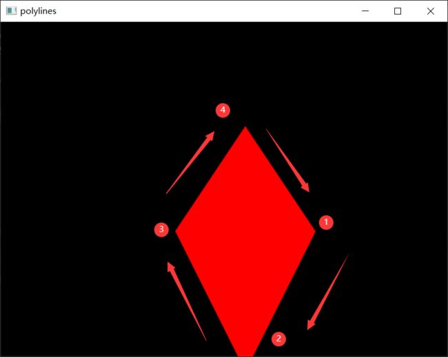
为了说明fillConvexPoly API,有:
	pts2 = np.array([(450, 300), (350, 500), (250, 300), (350, 150)], np.int32)
	# 调换第3和第4个点的顺序
    pts3 = np.array([(450, 300), (350, 500), (350, 150), (250, 300)], np.int32)
    cv2.fillConvexPoly(img, pts2, [0, 0, 255])
    cv2.imshow('polylines', img)
    cv2.waitKey(0)

    img2 = np.zeros((480, 640, 3), np.uint8)
    cv2.fillConvexPoly(img2, pts3, [0, 0, 255])

    cv2.imshow('fillConvexPoly', img2)
    cv2.waitKey(0)
    cv2.destroyAllWindows()
观察图像,点的先后顺序对填充图的影响至关重要
为啥是convex凸边形的填充没有再深入探究~
觉得有用的小伙伴点个赞加个关注支持一下吧!有错误或者不恰当的地方请指出!一起学习、进步!!!


