【Verilog】SPI总线的verilog实现
目录
一、SPI介绍
二、verilog代码实现
一、SPI介绍
SPI(Serial Peripheral Interface,串行外围设备接口),是Motorola公司提出的一种同步串行接口技术,是一种高速、全双工、同步通信总线,在芯片中只占用四根管脚用来控制及数据传输,广泛用于EEPROM、Flash、RTC(实时时钟)、ADC(数模转换器)、DSP(数字信号处理器)以及数字信号解码器上。SPI通信的速度很容易达到好几兆bps,所以可以用SPI总线传输一些未压缩的音频以及压缩的视频。
下图是只有2个chip利用SPI总线进行通信的结构图:
可知SPI总线传输只需要4根线就能完成,这四根线的作用分别如下:
- SCK(Serial Clock):SCK是串行时钟线,作用是Master向Slave传输时钟信号,控制数据交换的时机和速率;
- MOSI(Master Out Slave in):在SPI Master上也被称为Tx-channel,作用是SPI主机给SPI从机发送数据;
- CS/SS(Chip Select/Slave Select):作用是SPI Master选择与哪一个SPI Slave通信,低电平表示从机被选中(低电平有效);
- MISO(Master In Slave Out):在SPI Master上也被称为Rx-channel,作用是SPI主机接收SPI从机传输过来的数据;
SPI总线主要有以下几个特点:
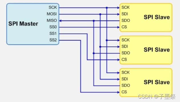
1、采用主从模式(Master-Slave)的控制方式,支持单Master多Slave。SPI规定了两个SPI设备之间通信必须由主设备Master来控制从设备Slave。也就是说,如果FPGA是主机的情况下,不管是FPGA给芯片发送数据还是从芯片中接收数据,写Verilog逻辑的时候片选信号CS与串行时钟信号SCK必须由FPGA来产生。同时一个Master可以设置多个片选(Chip Select)来控制多个Slave。SPI协议还规定Slave设备的clock由Master通过SCK管脚提供给Slave,Slave本身不能产生或控制clock,没有clock则Slave不能正常工作。单Master多Slave的典型结构如下图所示
2、 SPI总线在传输数据的同时也传输了时钟信号,所以SPI协议是一种同步(Synchronous)传输协议。Master会根据将要交换的数据产生相应的时钟脉冲,组成时钟信号,时钟信号通过时钟极性(CPOL)和时钟相位(CPHA)控制两个SPI设备何时交换数据以及何时对接收数据进行采样,保证数据在两个设备之间是同步传输的。
3、 SPI总线协议是一种全双工的串行通信协议,数据传输时高位在前,低位在后。SPI协议规定一个SPI设备不能在数据通信过程中仅仅充当一个发送者(Transmitter)或者接受者(Receiver)。在片选信号CS为0的情况下,每个clock周期内,SPI设备都会发送并接收1 bit数据,相当于有1 bit数据被交换了。数据传输高位在前,低位在后(MSB first)。SPI主从结构内部数据传输示意图如下图所示
SPI总线传输的模式:
SPI总线传输一共有4中模式,这4种模式分别由时钟极性(CPOL,Clock Polarity)和时钟相位(CPHA,Clock Phase)来定义,其中CPOL参数规定了SCK时钟信号空闲状态的电平,CPHA规定了数据是在SCK时钟的上升沿被采样还是下降沿被采样。这四种模式的时序图如下图所示:
模式0:CPOL= 0,CPHA=0。SCK串行时钟线空闲是为低电平,数据在SCK时钟的上升沿被采样,数据在SCK时钟的下降沿切换
模式1:CPOL= 0,CPHA=1。SCK串行时钟线空闲是为低电平,数据在SCK时钟的下降沿被采样,数据在SCK时钟的上升沿切换
模式2:CPOL= 1,CPHA=0。SCK串行时钟线空闲是为高电平,数据在SCK时钟的下降沿被采样,数据在SCK时钟的上升沿切换
模式3:CPOL= 1,CPHA=1。SCK串行时钟线空闲是为高电平,数据在SCK时钟的上升沿被采样,数据在SCK时钟的下降沿切换
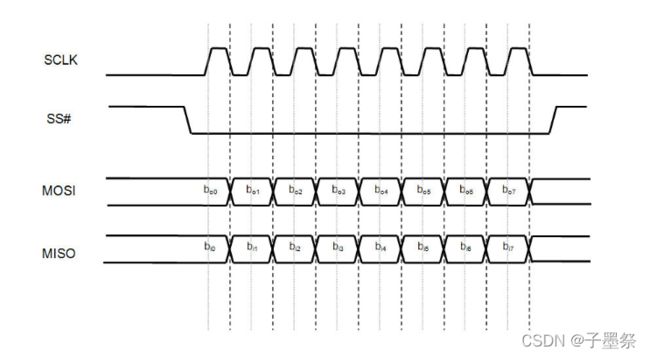
其中比较常用的模式是模式0和模式3。为了更清晰的描述SPI总线的时序,下面展现了模式0下的SPI时序图
上图清晰的表明在模式0下,在空闲状态下,SCK串行时钟线为低电平,当SS被主机拉低以后,数据传输开始,数据线MOSI和MISO的数据切换(Toggling)发生在时钟的下降沿(上图的黑色虚线),而数据线MOSI和MISO的数据的采样(Sampling)发生在数据的正中间(上图中的灰色实线)。下图清晰的描述了其他三种模式数据线MOSI和MISO的数据切换(Toggling)位置和数据采样位置的关系图
二、verilog代码实现
module spi_module
(
    input               I_clk       , // 全局时钟50MHz
    input               I_rst_n     , // 复位信号,低电平有效
    input               I_rx_en     , // 读使能信号
    input               I_tx_en     , // 发送使能信号
    input        [7:0]  I_data_in   , // 要发送的数据
    output  reg  [7:0]  O_data_out  , // 接收到的数据
    output  reg         O_tx_done   , // 发送一个字节完毕标志位
    output  reg         O_rx_done   , // 接收一个字节完毕标志位

    // 四线标准SPI信号定义
    input               I_spi_miso  , // SPI串行输入,用来接收从机的数据
    output  reg         O_spi_sck   , // SPI时钟
    output  reg         O_spi_cs    , // SPI片选信号
    output  reg         O_spi_mosi    // SPI输出,用来给从机发送数据
);

reg [3:0]   R_tx_state      ;
reg [3:0]   R_rx_state      ;

always @(posedge I_clk or negedge I_rst_n)
begin
    if(!I_rst_n)
        begin
            R_tx_state  <=  4'd0    ;
            R_rx_state  <=  4'd0    ;
            O_spi_cs    <=  1'b1    ;
            O_spi_sck   <=  1'b0    ;
            O_spi_mosi  <=  1'b0    ;
            O_tx_done   <=  1'b0    ;
            O_rx_done   <=  1'b0    ;
            O_data_out  <=  8'd0    ;
        end
    else if(I_tx_en) // 发送使能信号打开的情况下
        begin
            O_spi_cs    <=  1'b0    ; // 把片选CS拉低
            case(R_tx_state)
                4'd1, 4'd3 , 4'd5 , 4'd7  ,
                4'd9, 4'd11, 4'd13, 4'd15 : //整合奇数状态
                    begin
                        O_spi_sck   <=  1'b1                ;
                        R_tx_state  <=  R_tx_state + 1'b1   ;
                        O_tx_done   <=  1'b0                ;
                    end
                4'd0:    // 发送第7位
                    begin
                        O_spi_mosi  <=  I_data_in[7]        ;
                        O_spi_sck   <=  1'b0                ;
                        R_tx_state  <=  R_tx_state + 1'b1   ;
                        O_tx_done   <=  1'b0                ;
                    end
                4'd2:    // 发送第6位
                    begin
                        O_spi_mosi  <=  I_data_in[6]        ;
                        O_spi_sck   <=  1'b0                ;
                        R_tx_state  <=  R_tx_state + 1'b1   ;
                        O_tx_done   <=  1'b0                ;
                    end
                4'd4:    // 发送第5位
                    begin
                        O_spi_mosi  <=  I_data_in[5]        ;
                        O_spi_sck   <=  1'b0                ;
                        R_tx_state  <=  R_tx_state + 1'b1   ;
                        O_tx_done   <=  1'b0                ;
                    end
                4'd6:    // 发送第4位
                    begin
                        O_spi_mosi  <=  I_data_in[4]        ;
                        O_spi_sck   <=  1'b0                ;
                        R_tx_state  <=  R_tx_state + 1'b1   ;
                        O_tx_done   <=  1'b0                ;
                    end
                4'd8:    // 发送第3位
                    begin
                        O_spi_mosi  <=  I_data_in[3]        ;
                        O_spi_sck   <=  1'b0                ;
                        R_tx_state  <=  R_tx_state + 1'b1   ;
                        O_tx_done   <=  1'b0                ;
                    end
                4'd10:    // 发送第2位
                    begin
                        O_spi_mosi  <=  I_data_in[2]        ;
                        O_spi_sck   <=  1'b0                ;
                        R_tx_state  <=  R_tx_state + 1'b1   ;
                        O_tx_done   <=  1'b0                ;
                    end
                4'd12:    // 发送第1位
                    begin
                        O_spi_mosi  <=  I_data_in[1]        ;
                        O_spi_sck   <=  1'b0                ;
                        R_tx_state  <=  R_tx_state + 1'b1   ;
                        O_tx_done   <=  1'b0                ;
                    end
                4'd14:    // 发送第0位
                    begin
                        O_spi_mosi  <=  I_data_in[0]        ;
                        O_spi_sck   <=  1'b0                ;
                        R_tx_state  <=  R_tx_state + 1'b1   ;
                        O_tx_done   <=  1'b1                ;
                    end
                default:R_tx_state  <=  4'd0                ;
            endcase
        end
    else if(I_rx_en) // 接收使能信号打开的情况下
        begin
            O_spi_cs    <=  1'b0        ; // 拉低片选信号CS
            case(R_rx_state)
                4'd0, 4'd2 , 4'd4 , 4'd6  ,
                4'd8, 4'd10, 4'd12, 4'd14 : //整合偶数状态
                    begin
                        O_spi_sck      <=  1'b0                ;
                        R_rx_state     <=  R_rx_state + 1'b1   ;
                        O_rx_done      <=  1'b0                ;
                    end
                4'd1:    // 接收第7位
                    begin
                        O_spi_sck       <=  1'b1                ;
                        R_rx_state      <=  R_rx_state + 1'b1   ;
                        O_rx_done       <=  1'b0                ;
                        O_data_out[7]   <=  I_spi_miso          ;
                    end
                4'd3:    // 接收第6位
                    begin
                        O_spi_sck       <=  1'b1                ;
                        R_rx_state      <=  R_rx_state + 1'b1   ;
                        O_rx_done       <=  1'b0                ;
                        O_data_out[6]   <=  I_spi_miso          ;
                    end
                4'd5:    // 接收第5位
                    begin
                        O_spi_sck       <=  1'b1                ;
                        R_rx_state      <=  R_rx_state + 1'b1   ;
                        O_rx_done       <=  1'b0                ;
                        O_data_out[5]   <=  I_spi_miso          ;
                    end
                4'd7:    // 接收第4位
                    begin
                        O_spi_sck       <=  1'b1                ;
                        R_rx_state      <=  R_rx_state + 1'b1   ;
                        O_rx_done       <=  1'b0                ;
                        O_data_out[4]   <=  I_spi_miso          ;
                    end
                4'd9:    // 接收第3位
                    begin
                        O_spi_sck       <=  1'b1                ;
                        R_rx_state      <=  R_rx_state + 1'b1   ;
                        O_rx_done       <=  1'b0                ;
                        O_data_out[3]   <=  I_spi_miso          ;
                    end
                4'd11:    // 接收第2位
                    begin
                        O_spi_sck       <=  1'b1                ;
                        R_rx_state      <=  R_rx_state + 1'b1   ;
                        O_rx_done       <=  1'b0                ;
                        O_data_out[2]   <=  I_spi_miso          ;
                    end
                4'd13:    // 接收第1位
                    begin
                        O_spi_sck       <=  1'b1                ;
                        R_rx_state      <=  R_rx_state + 1'b1   ;
                        O_rx_done       <=  1'b0                ;
                        O_data_out[1]   <=  I_spi_miso          ;
                    end
                4'd15:    // 接收第0位
                    begin
                        O_spi_sck       <=  1'b1                ;
                        R_rx_state      <=  R_rx_state + 1'b1   ;
                        O_rx_done       <=  1'b1                ;
                        O_data_out[0]   <=  I_spi_miso          ;
                    end
                default:R_rx_state  <=  4'd0                    ;
            endcase
        end
    else
        begin
            R_tx_state  <=  4'd0    ;
            R_rx_state  <=  4'd0    ;
            O_tx_done   <=  1'b0    ;
            O_rx_done   <=  1'b0    ;
            O_spi_cs    <=  1'b1    ;
            O_spi_sck   <=  1'b0    ;
            O_spi_mosi  <=  1'b0    ;
            O_data_out  <=  8'd0    ;
        end
end

endmodule


