2.合宙Air32F103_USART
一、简介
本章目的:在上一章的基础上,添加串口的功能。可以实现串口的发送,中断接收,以及printf的重定向。
二、从例程移植
找到串口的例程:ModuleDemo\USART\USART_Asyn\USER\USART.uvprojx

关于串口中断的配置,在485的例程工程中有相关内容:

ModuleDemo\USART\USART_Rs485\USER\USART.uvprojx
三、移植
具体的移植过程,不再介绍了,将初始化和中断配置的部分复制过来就可以了。
3.1usart.c
在usart.c中包括初始化,发送单字节函数,printf重定向函数。以及接收中断服务子函数,将收到的数据直接发回。
| #include "usart.h" #include #include #include int fputc(int c, FILE *f) { /* Place your implementation of fputc here */ /* e.g. write a character to the USART */ usart1_1_byte(c); return c; } void uart1_init(uint32_t bound) { GPIO_InitTypeDef GPIO_InitStructure; USART_InitTypeDef USART_InitStructure; NVIC_InitTypeDef NVIC_InitStructe;
RCC_APB2PeriphClockCmd(RCC_APB2Periph_USART1, ENABLE); RCC_APB2PeriphClockCmd(RCC_APB2Periph_GPIOA, ENABLE); GPIO_InitStructure.GPIO_Pin = GPIO_Pin_9; GPIO_InitStructure.GPIO_Speed = GPIO_Speed_50MHz; GPIO_InitStructure.GPIO_Mode = GPIO_Mode_AF_PP; GPIO_Init(GPIOA, &GPIO_InitStructure); GPIO_InitStructure.GPIO_Pin = GPIO_Pin_10; GPIO_InitStructure.GPIO_Mode = GPIO_Mode_IN_FLOATING; GPIO_Init(GPIOA, &GPIO_InitStructure); USART_InitStructure.USART_BaudRate = bound; USART_InitStructure.USART_WordLength = USART_WordLength_8b; USART_InitStructure.USART_StopBits = USART_StopBits_1; USART_InitStructure.USART_Parity = USART_Parity_No; USART_InitStructure.USART_HardwareFlowControl = USART_HardwareFlowControl_None; USART_InitStructure.USART_Mode = USART_Mode_Rx | USART_Mode_Tx; NVIC_InitStructe.NVIC_IRQChannel = USART1_IRQn; NVIC_InitStructe.NVIC_IRQChannelCmd = ENABLE; NVIC_InitStructe.NVIC_IRQChannelPreemptionPriority = 1; NVIC_InitStructe.NVIC_IRQChannelSubPriority = 0; NVIC_Init(&NVIC_InitStructe);
USART_Init(USART1, &USART_InitStructure); USART_ITConfig(USART1, USART_IT_RXNE, ENABLE);//开启串口接受中断 USART_Cmd(USART1, ENABLE); } void usart1_1_byte(int ch) { while (!USART_GetFlagStatus(USART1, USART_FLAG_TC)); USART_SendData(USART1, (uint8_t)ch); while (!USART_GetFlagStatus(USART1, USART_FLAG_TC)); } void USART1_IRQHandler(void) //串口1中断服务程序 { u8 st,sbuf; st=USART_GetITStatus(USART1, USART_IT_RXNE); if(st==SET) // { sbuf=USART1->DR; usart1_1_byte(sbuf); } } |
3.2usart.h
| #ifndef __USART_H__ #define __USART_H__ #include "air32f10x.h" void uart1_init(uint32_t bound); void usart1_1_byte(int ch); #endif |
3.3main.c
main.c中包括初始化等操作。将官方例程中的CLK打印封装到CLK_Printf中。
| #include #include #include #include "delay.h" #include "led.h" #include "usart.h" void CLK_Printf(void); int main(void) { delay_init(); //延时初始化 uart1_init(115200); CLK_Printf();
LED_GPIO_Init();
printf("wuzjjj\r\n"); while (1) { LEDR_TOGGLE; delay_ms(200);//延时200ms
LEDG_TOGGLE; delay_ms(200);//延时200ms
LEDB_TOGGLE; delay_ms(200);//延时200ms } } void CLK_Printf(void) { RCC_ClocksTypeDef clocks; RCC_GetClocksFreq(&clocks); //获取系统时钟频率 printf("SYSCLK:%.1fMhz,HCLK:%.1fMhz,PCLK1:%.1fMhz,PCLK2:%.1fMhz,ADCCLK:%.1fMhz\r\n", (float)clocks.SYSCLK_Frequency/1000000,(float)clocks.HCLK_Frequency/1000000, (float)clocks.PCLK1_Frequency/1000000,(float)clocks.PCLK2_Frequency/1000000,(float)clocks.ADCCLK_Frequency/1000000); } |
四、调试
4.1下载程序
按照上一章的接线图,将A9 A10接到DAP-Link虚拟串口的A2 A3上。

4.2调试结果
复位后,打印当前的时钟频率。

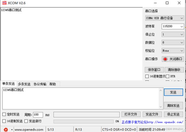
串口发送后将自动回复数据。