EasyARM-iMX257_U-Boot源代码移植分析
20150207Easy-ARMiMX257_U-Boot移植
2015-02-08 8:00 李海沿
I-mx257
u-boot-2009.08/cpu/arm926ejs
u-boot-2009.08/board/freescale
u-boot-2009.08/board/freescale/mx25_3stack
(1)、分析Makefile
首先我们分析Makefile,很容易发现在3210-3214行中,新增加了:
| mx25_3stack_config : unconfig @$(MKCONFIG) $(@:_config=) arm arm926ejs mx25_3stack freescale mx25
mx28_config : unconfig @$(MKCONFIG) $(@:_config=) arm arm926ejs mx28 freescale mx28 |
mx25_3stack_config 是针对 IMX25x 系列的开发板
è ./mkconfig mx25_3stack arm arm926ejs mx25_3stack freescale mx25
mx28_config 是针对 IMX28x 系列的开发板
è ./mkconfig mx28 arm arm926ejs mx28 freescale mx28
当我们运行makefile时,实际上运行的是上面的命令,下面我们来分析一下mkconfig。
./mkconfig mx25_3stack arm arm926ejs mx25_3stack freescale mx25
(2)、分析mkconfig
然后,我们来分析配置过程mkconfig,去掉它跟我们无关的代码:
| #./mkconfig mx25_3stack arm arm926ejs mx25_3stack freescale mx25 # $0 $1 $2 $3 $4 $5 $6
APPEND=no # Default: Create new config file BOARD_NAME="" # Name to print in make output
[ "${BOARD_NAME}" ] || BOARD_NAME="$1" #=> 单板的名字:BOARD_NAME = mx25_3stack
echo "Configuring for ${BOARD_NAME} board..." #=> 接下来会打印这句话
# Create link to architecture specific headers cd ./include rm -f asm ln -s asm-$2 asm #=> ln -s asm-arm asm # 在include下生成一个指向asm-arm的链接文件
rm -f asm-$2/arch #=> rm -f asm-arm arch
ln -s ${LNPREFIX}arch-$6 asm-$2/arch #=> ln -s arch-mx25 asm-arm/arch # 在include/asm-arm 下生成一个指向arch-mx25的链接文件
if [ "$2" = "arm" ] ; then rm -f asm-$2/proc ln -s ${LNPREFIX}proc-armv asm-$2/proc #=> ln -s arch-mx25 asm-arm/arch # 在include/asm-arm 下生成一个指向asm-arm/proc的链接文件 fi
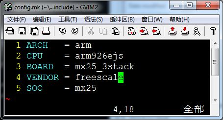
# # Create include file for Make # echo "ARCH = $2" > config.mk echo "CPU = $3" >> config.mk echo "BOARD = $4" >> config.mk # 生成config.mk 文件 内容如下: # ARCH = arm # CPU = arm926ejs # BOARD = mx25_3stack
[ "$5" ] && [ "$5" != "NULL" ] && echo "VENDOR = $5" >> config.mk # $5 = freescale 在config.mk中添加 # VENDOR = freescale
[ "$6" ] && [ "$6" != "NULL" ] && echo "SOC = $6" >> config.mk # $6 = mx25 在config.mk中添加 # SOC = mx25
# Create board specific header file > config.h # Create new config file
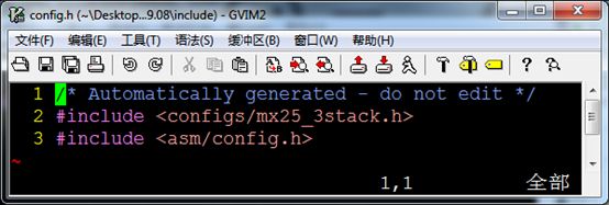
echo "/* Automatically generated - do not edit */" >>config.h echo "#include <configs/$1.h>" >>config.h echo "#include <asm/config.h>" >>config.h
#新建一个config.h文件,并添加以上信息
exit 0 |
从上面的mkconfig简化代码,我们得知,mkconfig中主要功能就是:
定义一些链接文件,生成config.mk、config.h内容如下:


可以看出,config.mk 和config.h 文件中的代码和我们分析的一模一样。
(3)、分析编译过程
分析编译过程 ,我们还是分析Makefile
| 157 # load ARCH, BOARD, and CPU configuration 158 include $(obj)include/config.mk 159 export ARCH CPU BOARD VENDOR SOC #紧跟上面的配置过程,这里mkconfig.mk就是上一步生成的一些开发板的相关信息
172 OBJS = cpu/$(CPU)/start.o # OBJS = cpu/arm926ejs/start.o
186 LIBS = lib_generic/libgeneric.a
191 LIBS += cpu/$(CPU)/lib$(CPU).a # LIBS += cpu/ arm926ejs/lib arm926ejs.a
254 LIBBOARD = board/$(BOARDDIR)/lib$(BOARD).a 255 LIBBOARD := $(addprefix $(obj),$(LIBBOARD)) # LIBBOARD = board/ freescale /mx25_3stack/libmx25_3stack.a
295 ALL += $(obj)u-boot.srec $(obj)u-boot.bin $ (obj)System.map $(U_BOOT_NAND) $(U_BOOT_ONENAND) 296 all: $(ALL)
280 U_BOOT_NAND = $(obj)u-boot-nand.bin 285 U_BOOT_ONENAND = $(obj)u-boot-onenand.bin
302 $(obj)u-boot.srec: $(obj)u-boot 303 $(OBJCOPY) -O srec $< $@
305 $(obj)u-boot.bin: $(obj)u-boot 306 $(OBJCOPY) ${OBJCFLAGS} -O binary $< $@ #这个u-boot是一个elf格式 的可执行文件
450 $(obj)System.map: $(obj)u-boot 451 @$(call SYSTEM_MAP,$<) > $(obj)System.map
|
在\board\freescale\mx25_3stack的u-boot.lsd链接脚本中,定义了,所有数据在内存中的排放方式
在config.mk中定义了数据排放的地址
| LDSCRIPT := $(SRCTREE)/board/$(VENDOR)/$(BOARD)/u-boot.lds
TEXT_BASE = 0x83F00000 |
在 u-boot.lsd中定义了排放顺序
| . = 0x00000000; #从config.mk知,下面的数据从TEXT_BASE = 0x83F00000开始排放
. = ALIGN(4); .text : { #代码段排放顺序 board/freescale/mx25_3stack/dcdheader.o (.text) cpu/arm926ejs/start.o (.text) *(.text) } #所有文件的只读数据段 . = ALIGN(4); .rodata : { *(.rodata) } #所有文件的数据段 . = ALIGN(4); .data : { *(.data) }
. = ALIGN(4); .got : { *(.got) }
. = .; __u_boot_cmd_start = .; #所有文件的u_boot_cmd段,u-boot自定义的段 .u_boot_cmd : { *(.u_boot_cmd) } __u_boot_cmd_end = .;
. = ALIGN(4); __bss_start = .; .bss : { *(.bss) } _end = .; |
从上面得知,我们的代码将会从
我们代码的运行顺序是 dcdheader.s => start.s => *
所以我们,从dcdheader.s 和 start.s 开始分析
(4)、分析第一阶段start.s分析
第一阶段:dcdheader.s和start.s分析
cdcheader.s中主要是对开发板的一些内存MDDR,DDR2等的一些初始化,看不懂可以跳过
|
.extern reset
#define DCDGEN(i,type, addr, data) \ dcd_##i: ;\ .long type ;\ .long addr ;\ .long data
.globl _initheader _initheader: b reset .org 0x400 app_code_jump_v: .long reset app_code_barker: .long 0xB1 app_code_csf: .long 0 hwcfg_ptr_ptr: .long hwcfg_ptr super_root_key: .long 0 hwcfg_ptr: .long dcd_data app_dest_ptr: .long TEXT_BASE dcd_data: .long 0xB17219E9
#ifdef MXC_MEMORY_MDDR dcd_len: .long 12*15 #else dcd_len: .long 12*24 #endif
/* WEIM config-CS5 init -- CPLD */ DCDGEN( 1, 4, 0xB8002050, 0x0000D843) /* CS5_CSCRU */ DCDGEN( 2, 4, 0xB8002054, 0x22252521) /* CS5_CSCRL */ DCDGEN( 3, 4, 0xB8002058, 0x22220A00) /* CS5_CSCRA */ #ifdef MXC_MEMORY_MDDR /* MDDR init */ DCDGEN( 4, 4, 0xB8001010, 0x00000004) /* enable mDDR */ DCDGEN( 5, 4, 0xB8001000, 0x92100000) /* precharge command */ DCDGEN( 6, 1, 0x80000400, 0x12344321) /* precharge all dummy write */ DCDGEN( 7, 4, 0xB8001000, 0xA2100000) /* auto-refresh command */ DCDGEN( 8, 4, 0x80000000, 0x12344321) /* dummy write for refresh */ DCDGEN( 9, 4, 0x80000000, 0x12344321) /* dummy write for refresh */ DCDGEN(10, 4, 0xB8001000, 0xB2100000) /* Load Mode Reg command - cas=3 bl=8 */ DCDGEN(11, 1, 0x80000033, 0xda) /* dummy write -- address has the mode bits */ DCDGEN(12, 1, 0x81000000, 0xff) /* dummy write -- address has the mode bits */ DCDGEN(13, 4, 0xB8001000, 0x82216880) DCDGEN(14, 4, 0xB8001004, 0x00295729) #else /* DDR2 init */ DCDGEN( 4, 4, 0xB8001004, 0x0076E83A) /* initial value for ESDCFG0 */ DCDGEN( 5, 4, 0xB8001010, 0x00000204) /* ESD_MISC */ DCDGEN( 6, 4, 0xB8001000, 0x92210000) /* CS0 precharge command */ DCDGEN( 7, 4, 0x80000f00, 0x12344321) /* precharge all dummy write */ DCDGEN( 8, 4, 0xB8001000, 0xB2210000) /* Load Mode Register command */ DCDGEN( 9, 1, 0x82000000, 0xda) /* dummy write Load EMR2 */ DCDGEN(10, 1, 0x83000000, 0xda) /* dummy write Load EMR3 */ DCDGEN(11, 1, 0x81000400, 0xda) /* dummy write Load EMR1; enable DLL */ DCDGEN(12, 1, 0x80000333, 0xda) /* dummy write Load MR; reset DLL */
DCDGEN(13, 4, 0xB8001000, 0x92210000) /* CS0 precharge command */ DCDGEN(14, 1, 0x80000400, 0x12345678) /* precharge all dummy write */
DCDGEN(15, 4, 0xB8001000, 0xA2210000) /* select manual refresh mode */ DCDGEN(16, 4, 0x80000000, 0x87654321) /* manual refresh */ DCDGEN(17, 4, 0x80000000, 0x87654321) /* manual refresh twice */
DCDGEN(18, 4, 0xB8001000, 0xB2210000) /* Load Mode Register command */ DCDGEN(19, 1, 0x80000233, 0xda) /* Load MR; CL=3, BL=8, end DLL reset */ DCDGEN(20, 1, 0x81000780, 0xda) /* Load EMR1; OCD default */ DCDGEN(21, 1, 0x81000400, 0xda) /* Load EMR1; OCD exit */ DCDGEN(22, 4, 0xB8001000, 0x82216080) /* normal mode */ DCDGEN(23, 4, 0x43FAC454, 0x00001000) /* IOMUXC_SW_PAD_CTL_GRP_DDRTYPE(1-5) */ #endif
DCDGEN(99, 4, 0x53F80008, 0x20034000) /* CLKCTL ARM=400 AHB=133 */ card_cfg: .long UBOOT_IMAGE_SIZE |
start.s主要的功能就是:
关闭看门狗,初始化时钟,初始化SDRAM,设置栈,读出内核,跳到内核启动的C函数开始启动内核。
| .globl reset reset: /** set the cpu to SVC32 mode 设置为SVC32管理模式*/ mrs r0,cpsr bic r0,r0,#0x1f orr r0,r0,#0xd3 msr cpsr,r0 / * CPU的初始化 屏蔽中断 初始化SDRAM 设置时钟*/ bl cpu_init_crit
/*重定位 */ relocate: /* relocate U-Boot to RAM */ adr r0, _start /* r0 <- current position of code */ ldr r1, _TEXT_BASE /* test if we run from flash or RAM */ cmp r0, r1 /* don't reloc during debug */ beq stack_setup /* 设置栈 */
ldr r2, _armboot_start ldr r3, _bss_start sub r2, r3, r2 /* r2 <- size of armboot */ add r2, r0, r2 /* r2 <- source end address */ /* 拷贝代码 flash => SDRAM */ copy_loop: ldmia r0!, {r3-r10} /* copy from source address [r0] */ stmia r1!, {r3-r10} /* copy to target address [r1] */ cmp r0, r2 /* until source end addreee [r2] */ ble copy_loop /* 设置栈 */ /* Set up the stack */ stack_setup: ldr r0, _TEXT_BASE /* upper 128 KiB: relocated uboot */ sub r0, r0, #CONFIG_SYS_MALLOC_LEN /* malloc area */ sub r0, r0, #CONFIG_SYS_GBL_DATA_SIZE /* bdinfo */ #ifdef CONFIG_USE_IRQ sub r0, r0, #(CONFIG_STACKSIZE_IRQ+CONFIG_STACKSIZE_FIQ) #endif sub sp, r0, #12 /* leave 3 words for abort-stack */ /* 清除bss段 */ clear_bss: ldr r0, _bss_start /* find start of bss segment */ ldr r1, _bss_end /* stop here */ mov r2, #0x00000000 /* clear */
bl coloured_LED_init //调用心脏LED灯初始化 bl red_LED_on //点亮红色LED灯 /* 跳转到第二阶段,用C语言实现的更多的功能*/ ldr pc, _start_armboot |
无论从NOR Flash启动还是从NAND Flash启动
地址0处为指令 "b Reset",机器码为 0XEA00000B
对于从 NAND Flash启动的情况,起开始4KB的代码会复制到CPU内部4K内存中
对于从 NOR Flash启动的情况,NOR Flash的开始地址为0
对于 NOR Flash必须通过一定的命令序列才能实现写数据
所以可以根据这点差别来分辨是从NAND Flash 还是NOR Flash启动;
向地址0写入一个数据,然后读出来,如果地址上的值没有改变的话,也就是零地址不可写,那就是NOR Flash
(5)、分析第二阶段
第二阶段
我们跟踪start_armboot,跳转到根目录的/u-boot/lib_arm/board.c文件中
此阶段我们主要的工作就是 启动内核①从falsh读出内核②启动内核
所以我们必须要有的功能
1.对flash的初始化,读写功能
| /* 1.falsh_init()会识别出是falsh的类别 */ /* configure available FLASH banks */ display_flash_config (flash_init ()); /* 2.对flash的初始化,读写功能 */ #if defined(CONFIG_CMD_NAND) puts ("NAND: "); nand_init(); /* go init the NAND */ #endif /* 3环境变量的初始化 */ /* initialize environment */ env_relocate (); /* 4串口初始化 */ serial_initialize(); /* 5. 网络IP设置 IP Address */ gd->bd->bi_ip_addr = getenv_IPaddr ("ipaddr"); /*6. 最终进过一系列的初始化,进入主循环 ,等要用户在u-boot命令后输入命令*/ /* main_loop() can return to retry autoboot, if so just run it again. */ for (;;) { main_loop (); } /*主循环中主要就是对命令的接收与解析,运行相应的函数 readline('读入串口输入的命令'); run_command; 所以也可以说U-Boot的核心就是这些命令 */ |
接下来我们打开common/main.c文件
在文件中主要是打印U-Boot中的一些到倒计时,判断开发者输入的命令等
启动内核
nand reda.jffs 0x80800000 kernel
boom 0x80800000
(6)、分析命令的实现
命令的实现,向U-Boot中增加自定义命令
我们在u-boot下增加我们自定义hello命令。
首先我们在u-boot的common目录下增加一个cmd_hello.c文件
参照其他命令的书写方式,代码如下
| #include <image.h> #include <malloc.h> #include <u-boot/zlib.h> #include <bzlib.h> #include <environment.h> #include <lmb.h> #include <linux/ctype.h> #include <asm/byteorder.h>
int do_hello (cmd_tbl_t *cmdtp, int flag, int argc, char *argv[]) { int i = 0; printf("hello,Lover雪!!!\nthe argcs are \n"); for(i = 0 ; i<argc ; i++) printf("argv[%d]: %s\n",i,argv[i]); return 0; }
U_BOOT_CMD( hello, CONFIG_SYS_MAXARGS, 1, do_hello, "This is a user defined command hello,Lover雪!!!", "hello,long help ......\n" ); |
修改common下面的makefile文件,告诉U-Boot编译我们自定义的C文件
参考Makefile中其他文件的定义,加入一句
| COBJS-y += cmd_hello.o |
重新make编译 u-boot