三维激光重建原理与实现HALCON
下面这个例子是演示线激光和单目相机实现三维重建
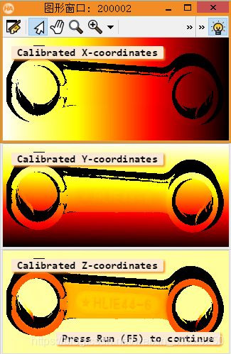
下面是运行的结果,这也是HALCON中的一个示例
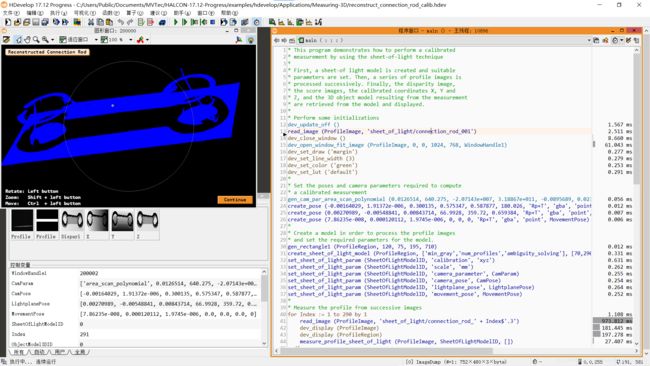
直接从代码出发来看,大部分算子说明在之前的文章中有介绍,可以参考:
* This program demonstrates how to perform a calibrated
* measurement by using the sheet-of-light technique
*
* //此程序演示如何执行校准
*// 使用光片技术进行测量
* First, a sheet-of light model is created and suitable
* parameters are set. Then, a series of profile images is
* processed successively. Finally, the disparity image,
* the score images, the calibrated coordinates X, Y and
* Z, and the 3D object model resulting from the measurement
* are retrieved from the model and displayed.
* //首先,创建光平面模型,并且设置一定的参数
* //然后,一系列的激光图像先后被处理
* //最后,从模型中检索和显示差异图像、分数图像、校准坐标 X、Y 和 Z 以及测量产生的 3D 对象模型。
*
* Perform some initializations
* //初始化
dev_update_off ()
read_image (ProfileImage, 'sheet_of_light/connection_rod_001')
dev_close_window ()
dev_open_window_fit_image (ProfileImage, 0, 0, 1024, 768, WindowHandle1)
dev_set_draw ('margin')
dev_set_line_width (3)
dev_set_color ('green')
dev_set_lut ('default')
*
* Set the poses and camera parameters required to compute
* a calibrated measurement
* //设置相机模型参数
gen_cam_par_area_scan_polynomial (0.0126514, 640.275, -2.07143e+007, 3.18867e+011, -0.0895689, 0.0231197, 6.00051e-006, 6e-006, 387.036, 120.112, 752, 240, CamParam)
*//创建相机姿态参数
create_pose (-0.00164029, 1.91372e-006, 0.300135, 0.575347, 0.587877, 180.026, 'Rp+T', 'gba', 'point', CamPose)
*//创建光平面姿态参数
create_pose (0.00270989, -0.00548841, 0.00843714, 66.9928, 359.72, 0.659384, 'Rp+T', 'gba', 'point', LightplanePose)
*//创建移动方程
create_pose (7.86235e-008, 0.000120112, 1.9745e-006, 0, 0, 0, 'Rp+T', 'gba', 'point', MovementPose)
*
* Create a model in order to process the profile images
* and set the required parameters for the model.
* //创建一个矩形区域
gen_rectangle1 (ProfileRegion, 120, 75, 195, 710)
*//创建光平面模型
create_sheet_of_light_model (ProfileRegion, ['min_gray','num_profiles','ambiguity_solving'], [70,290,'first'], SheetOfLightModelID)
*//下面都是设置光平面模型参数
set_sheet_of_light_param (SheetOfLightModelID, 'calibration', 'xyz')
set_sheet_of_light_param (SheetOfLightModelID, 'scale', 'mm')
set_sheet_of_light_param (SheetOfLightModelID, 'camera_parameter', CamParam)
set_sheet_of_light_param (SheetOfLightModelID, 'camera_pose', CamPose)
set_sheet_of_light_param (SheetOfLightModelID, 'lightplane_pose', LightplanePose)
set_sheet_of_light_param (SheetOfLightModelID, 'movement_pose', MovementPose)
*
* Measure the profile from successive images
* //从连续图像中测量配置文件
for Index := 1 to 290 by 1
    read_image (ProfileImage, 'sheet_of_light/connection_rod_' + Index$'.3')
    dev_display (ProfileImage)
    dev_display (ProfileRegion)
    *//这个算子应该就是最重要的了,通过光平面模型对图像进行处理
    measure_profile_sheet_of_light (ProfileImage, SheetOfLightModelID, [])
endfor
* Get the resulting images and close the sheet-of-light handle
* //获得结果
get_sheet_of_light_result (Disparity, SheetOfLightModelID, 'disparity')
get_sheet_of_light_result (X, SheetOfLightModelID, 'x')
get_sheet_of_light_result (Y, SheetOfLightModelID, 'y')
get_sheet_of_light_result (Z, SheetOfLightModelID, 'z')
*//获得以光片技术作为 3D 对象模型进行校准测量的结果。
get_sheet_of_light_result_object_model_3d (SheetOfLightModelID, ObjectModel3DID)
*//清除模型
clear_sheet_of_light_model (SheetOfLightModelID)
*
* Display the disparity image
* //显示差异图像
get_image_size (Disparity, Width, Height)
dev_set_window_extents (0, 0, Width, Height)
dev_set_lut ('temperature')
set_display_font (WindowHandle1, 14, 'mono', 'true', 'false')
dev_clear_window ()
dev_display (Disparity)
disp_message (WindowHandle1, 'Disparity', 'window', 12, 12, 'black', 'true')
disp_continue_message (WindowHandle1, 'black', 'true')
stop ()
*
* Display the Z-coordinates
dev_close_window ()
dev_open_window (Height + 10, 0, Width * .5, Height * .5, 'black', WindowHandle3)
set_display_font (WindowHandle3, 14, 'mono', 'true', 'false')
dev_display (Z)
disp_message (WindowHandle3, 'Calibrated Z-coordinates', 'window', 12, 12, 'black', 'true')
*
* Display the Y-coordinates
dev_open_window ((Height + 10) * .5, 0, Width * .5, Height * .5, 'black', WindowHandle2)
set_display_font (WindowHandle2, 14, 'mono', 'true', 'false')
dev_display (Y)
disp_message (WindowHandle2, 'Calibrated Y-coordinates', 'window', 12, 12, 'black', 'true')
*
* Display the X-coordinates
dev_open_window (0, 0, Width * .5, Height * .5, 'black', WindowHandle1)
dev_display (X)
dev_set_lut ('default')
set_display_font (WindowHandle1, 14, 'mono', 'true', 'false')
disp_message (WindowHandle1, 'Calibrated X-coordinates', 'window', 12, 12, 'black', 'true')
disp_continue_message (WindowHandle3, 'black', 'true')
stop ()
*
* Display the 3d object model
* //创建相机模型
gen_cam_par_area_scan_division (0.012, 0, 6e-006, 6e-006, 376, 240, 752, 480, CameraParam1)
Instructions[0] := 'Rotate: Left button'
Instructions[1] := 'Zoom:   Shift + left button'
Instructions[2] := 'Move:   Ctrl  + left button'
create_pose (0, -10, 300, -30, 0, -30, 'Rp+T', 'gba', 'point', PoseIn)
dev_close_window ()
dev_close_window ()
dev_close_window ()
get_cam_par_data (CameraParam1, 'image_width', Width)
get_cam_par_data (CameraParam1, 'image_height', Height)
dev_open_window (0, 0, Width, Height, 'black', WindowHandle)
set_display_font (WindowHandle, 14, 'mono', 'true', 'false')
visualize_object_model_3d (WindowHandle, ObjectModel3DID, CameraParam1, PoseIn, 'color', 'blue', 'Reconstructed Connection Rod', '', Instructions, PoseOut)
* //清除3D模型
clear_object_model_3d (ObjectModel3DID)