深蓝学院-视觉SLAM课程-第7讲作业:SLAM中g2o入门详解,直接法BA
1. 引言
在SLAM中,BA是个重要的部分,前后端很多地方都用得到,而g2o是一个很重要的使用图优化求解优化问题的库,所以有必要熟练掌握,尽管有了些C++的底子,但是看g2o的代码还是比较吃力,所以开帖学习,同时输出。
本文主要参考博客:g2o的简介、安装、使用说明和曲线拟合例程
关于图和超图,主要不同在于图中边上顶点个数的不同,在普通图中,一条边包含1或2个顶点,在超图中,边被称为超边(hyperedge),一条边包含多个顶点。含有一对多和一对一关系的图就称为超图,HyperGraph有has-many关系,Vertex和Edge都是class,在HyperGraph中分别定义了它们的集合set,故是超图。
关于自己定义边时,这篇白巧克力的博客里面提到自己定义边的时候不需要使用宏函数
G2O_USE_TYPE_GROUP(slam3d);
2. g2o使用步骤理解
大概有6步,只要把握住了这6步,基本上g2o就能用起来了。
- 创建一个线性求解器LinearSolver。
- 创建BlockSolver,并用上面定义的线性求解器初始化。
- 创建总求解器solver,并从GN/LM/DogLeg 中选一个作为迭代策略,再用上述块求解器BlockSolver初始化。
- 创建图优化的核心:稀疏优化器(SparseOptimizer)。
- 定义图的顶点和边,并添加到SparseOptimizer中。
- 设置优化参数,开始执行优化。
对照着slambook2/ch6/g2oCurveFitting.cpp曲线拟合的例程来看
#include 一步步来拆解,首先对问题进行定性:
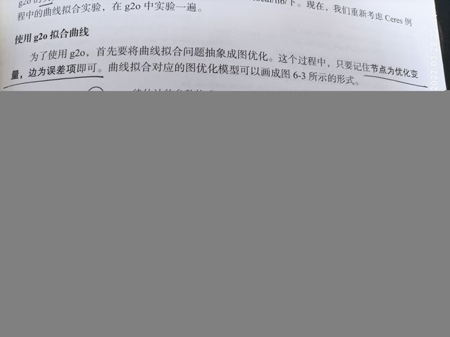
待估计目标是曲线 y = e a x 2 + b x + c + w y=e^{ax^2+bx+c}+w y=eax2+bx+c+w的参数a,b,c,其中w是高斯噪声,数据是曲线的横坐标x,观测是曲线的纵坐标y,那么遵循节点为优化变量,边为误差项的原则,节点数据类型可以定义为一个三维向量 [ a , b , c ] T [a,b,c]^T [a,b,c]T,边的数据类型是double,误差和原来一样是误差=观测-预测,于是就出现了教材上的这张华为图:
然后顺着main往下走:
首先是生成数据,这就不说了。
接下来就是刚才提到的6步法:
2.1&2.2. 创建BlockSolver,创建一个线性求解器LinearSolver
//1,2:创建blocksolver并使用linearsolver对其进行初始化
typedef g2o::BlockSolver<g2o::BlockSolverTraits<3,1>> BlockSolverType;
//定义linearsolver为LinearSolverDense,继承自类模板LinearSolver,传入参数MatrixType后实例化为模板类
typedef g2o::LinearSolverDense<BlockSolverType::PoseMatrixType> LinearSolverType;  //使用dense cholesky分解法
这里代码嵌套比较多,不好理解,参考了g2o的简介、安装、使用说明和曲线拟合例程
看了g2o的那张代码框架图之后立马就觉得好懂多了,摘抄一部分博客内容:
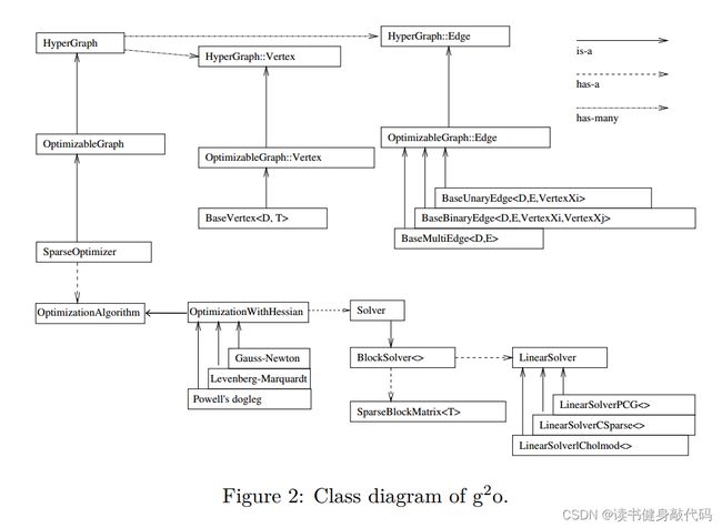
- 整个g2o框架可以分为上下两部分,两部分中间的连接点:SparseOptimizer 就是整个g2o的核心部分。
- 往上看,SparseOptimizer是一个派生类,其实是一个Optimizable Graph,从而也是一个超图(HyperGraph)。
- 超图有很多顶点和边。顶点继承自 Base Vertex,也即OptimizableGraph::Vertex;而边可以继承自 BaseUnaryEdge(单边),
BaseBinaryEdge(双边)或BaseMultiEdge(多边),它们都叫做OptimizableGraph::Edge。- 往下看,SparseOptimizer包含一个优化算法部分OptimizationAlgorithm,它是通过OptimizationWithHessian
来实现的。其中迭代策略可以从Gauss-Newton(高斯牛顿法,简称GN)、Levernberg-Marquardt(简称LM法)和Powell’s dogleg中选择。- 对优化算法部分进行求解的时求解器solver,它实际由BlockSolver组成。BlockSolver由两部分组成:一个是SparseBlockMatrix,它由于求解稀疏矩阵(雅克比和海塞);另一个部分是LinearSolver,它用来求解线性方程H △ x = − b H\triangle x = -bH△x=−b 得到待求增量,因此这一部分是非常重要的,它可以从PCG/CSparse/Choldmod选择求解方法。
所以上面的两个typedef就是做一个blocksolver和linearsolver的命名简化,紧接着第3步
2.3. 创建总求解器solver
//3.创建总求解器solver,选择一个优化算法,BlockSolver<-LinearSolver
// 并使用BlockSolver的unique_ptr指针初始化,而BlockSolver又是使用LinearSolver的unique_ptr来初始化的
auto solver = new g2o::OptimizationAlgorithmGaussNewton(g2o::make_unique<BlockSolverType>(g2o::make_unique<LinearSolverType>()));
使用LinearSolver的unique_ptr初始化BlockSolver的成员,该成员也是L-M优化算法中的unique_ptr,确定了这些实参之后就new一个L-M求解器solver。
2.4. 创建图优化的核心:稀疏优化器(SparseOptimizer)
g2o::SparseOptimizer optimizer; //图模型
optimizer.setAlgorithm(solver); //
optimizer.setVerbose(true); //打开调试输出
这个SparseOptimizer就是框架图中的中间部分。
2.5. 定义顶点和边,并添加到图中(难点)
由于本问题比较简单,所以此部分不会太复杂,但是核心是定义自己的顶点和边。
整张图只有一个顶点,数据类型是三维向量;边是一元边,从自己出发指向自己。
    //往图中增加顶点,是abc三维向量
    CurveFittingVertex *v = new CurveFittingVertex();  //new一个顶点对象并指向它
    v->setEstimate(Eigen::Vector3d(ae, be, ce));  //设置估计初始值
    v->setId(0);    //设置顶点的编号
    optimizer.addVertex(v);
    // 往图中增加边,设置边的属性,然后加入到优化器中
    for(int i=0; i<N; ++i)
    {
        CurveFittingEdge* edge = new CurveFittingEdge(x_data[i]);
        edge->setId(i);
        edge->setVertex(0,v);               // 设置连接的顶点,这里只有一个顶点,所以是第0个顶点。v是定义的Vertex对象的指针,如果使用
        edge->setMeasurement(y_data[i]);    // 观测数值
        // 信息矩阵:协方差矩阵之逆(对角阵的逆是对角阵的各个元素的倒数组成的矩阵)
        edge->setInformation(Eigen::Matrix<double, 1, 1>::Identity() * 1/ (w_sigma * w_sigma));
        optimizer.addEdge(edge);
    }
这里用到了我们自定义的顶点和边
//这里需要优化的变量是曲线的abc参数,所以参数1:3维,参数2:用3维向量来表示。
class CurveFittingVertex : public g2o::BaseVertex<3, Eigen::Vector3d>
{
public:
    EIGEN_MAKE_ALIGNED_OPERATOR_NEW   //内存对齐宏,重载了new函数,使得分配的对象都是16Bytes对齐的

    // 重置,把估计值置0即可
    virtual void setToOriginImpl() override {
        _estimate <<0,0,0;
    }

    // 更新   处理xk+1 = xk + ∆x,每个优化的加法运算不一致,可能还包括向量,所以需要重写。
    virtual void oplusImpl(const double *update) override
    {
        _estimate +=Eigen::Vector3d(update);
    }

    virtual bool read(istream &in) {}

    virtual bool write(ostream &out) const {}
};

//一元边(相当于仅优化相机位姿),参数1:观测值的维度(这里是y,一维);参数2:观测值类型;参数3:顶点类型,这里是自定义的顶点
class CurveFittingEdge : public g2o::BaseUnaryEdge<1,double,CurveFittingVertex>
{
public:
    EIGEN_MAKE_ALIGNED_OPERATOR_NEW
    CurveFittingEdge(double x): BaseUnaryEdge(), _x(x){}  //构造函数,先执行基类构造函数,再执行剩余的初始化部分

    //
    //虚函数:基类的指针和引用,指向派生类,调用派生类的虚函数;指向基类,调用基类的虚函数
    virtual void computeError() override  //使用override显式地声明虚函数覆盖
    {
        const CurveFittingVertex *v = static_cast<const CurveFittingVertex *>(_vertices[0]);  //_vertices是pyper_graph.h中的
        const Eigen::Vector3d abc = v->estimate();
        _error(0, 0) = _measurement - std::exp(abc(0, 0) * _x * _x + abc(1,0)*_x + abc(2,0));   //定义误差=观测-预测
    }

    virtual void linearizeOplus() override
    {
        const CurveFittingVertex* v = static_cast<const CurveFittingVertex *>(_vertices[0]);
        const Eigen::Vector3d abc = v->estimate();
        double y = std::exp(abc[0] * _x * _x + abc[1]*_x + abc[2]);
        //J=观测-预测    (\partial J)/(\partial a)  (\partial J)/(\partial b)  (\partial J)/(\partial c)
        _jacobianOplusXi[0] = -_x * _x * y;
        _jacobianOplusXi[1] = -_x * y;
        _jacobianOplusXi[2] = -y;
    }

    virtual bool read(istream &in) {}
    virtual bool write(ostream &out) const {}

public:
    double _x;   // x是数据, y为 _measurement观测

};
这里有一个细节EIGEN_MAKE_ALIGNED_OPERATOR_NEW是关于Eigen中的vector对齐的问题,感兴趣的可以看2.5.1这一节,不感兴趣的直接跳到2.5.2节,总之一句话:EIGEN_MAKE_ALIGNED_OPERATOR_NEW使得vector中的元素按照16Bytes的大小在内存中对齐。
2.5.1. 细节
class CurveFittingVertex : public g2o::BaseVertex<3, Eigen::Vector3d> {
public:
  EIGEN_MAKE_ALIGNED_OPERATOR_NEW

  // 重置(顶点的重置函数,把估计值置0即可)
  virtual void setToOriginImpl() override {
    _estimate << 0, 0, 0;
  }

  // 更新
  virtual void oplusImpl(const double *update) override {
    _estimate += Eigen::Vector3d(update);
  }

  // 存盘和读盘:留空
  virtual bool read(istream &in) {}

  virtual bool write(ostream &out) const {}
};
在定义顶点和边的时候其中有句话看不太懂
EIGEN_MAKE_ALIGNED_OPERATOR_NEW
这句话是强制让分配对象的时候,就给一个16byte对齐的地址。
关于对齐,之前看到过vector的对齐,但是很奇怪为什么要对对齐进行特殊设置,今天来探究一下。
在slambook2/ch8/direct_method开头定义了存放二维vector的vector(实际上就是二维,不过数据也是二维vector),并有个对齐参数aligned_allocator
typedef vector<Eigen::Vector2d, Eigen::aligned_allocator<Eigen::Vector2d>> VecVector2d;
查了一下,这句话是用来自定义vector的对齐方式的,主要参考了这篇博客。
简单来说,vector默认会把push进去的数据按照连续内存来存放,SSE支持128bit的多指令并行,但是使用SSE有个要求就是处理的对象必须要在内存地址以16byte整数倍的地方开始。
但是,如果把一些Eigen的结构放到std的容器里面,比如vector,map。这些容器会把一个一个的Eigen结构在内存里面连续排放。
可以想象,如果这些Eigen的结构本身不是16byte大小,一连续排放后,自然有很多对象就不是在16byte整数倍的地方开始了。为了让对象进行16byte对齐,有下面的一种解决方法:
std::vector<Eigen::Vector4f,Eigen::aligned_allocator<Eigen::Vector4f> >
强制在定义变量时,就给一个16byte对齐的地址。
所以在slambook2/ch6/g2oCurveFitting中定义顶点CurveFittingVertex的时候使用了EIGEN_MAKE_ALIGNED_OPERATOR_NEW
这句话实际上会重载new函数,强制让分配对象的时候,就给一个16byte对齐的地址。
原因分析:
对象内部的内存分配是相对与对象的地址的。如果对象的地址不是16byte对齐的,里面的成员并不会知道这个信息,所以没有办法分配16byte对齐的地址。
2.5.2 代码讲解
顶点主要是重写更新函数,主要是因为为了匹配各种数据结构,需要对更新函数进行重写
    virtual void oplusImpl(const double *update) override
    {
        _estimate +=Eigen::Vector3d(update);
    }
边主要是计算误差和雅可比
    //虚函数:基类的指针和引用,指向派生类,调用派生类的虚函数;指向基类,调用基类的虚函数
    virtual void computeError() override  //使用override显式地声明虚函数覆盖
    {
        const CurveFittingVertex *v = static_cast<const CurveFittingVertex *>(_vertices[0]);  //_vertices是pyper_graph.h中的
        const Eigen::Vector3d abc = v->estimate();
        _error(0, 0) = _measurement - std::exp(abc(0, 0) * _x * _x + abc(1,0)*_x + abc(2,0));   //定义误差=观测-预测
    }

    virtual void linearizeOplus() override
    {
        const CurveFittingVertex* v = static_cast<const CurveFittingVertex *>(_vertices[0]);
        const Eigen::Vector3d abc = v->estimate();
        double y = std::exp(abc[0] * _x * _x + abc[1]*_x + abc[2]);
        //J=观测-预测    (\partial J)/(\partial a)  (\partial J)/(\partial b)  (\partial J)/(\partial c)
        _jacobianOplusXi[0] = -_x * _x * y;
        _jacobianOplusXi[1] = -_x * y;
        _jacobianOplusXi[2] = -y;
    }
误差还是观测-预测,取出estimate()后,带入曲线方程算出y值,和观测值相减即得error。
雅可比也很好理解: J = min a , b , c 1 2 ∑ i = 1 N ∣ ∣ y i − e a x i 2 + b x i + c ∣ ∣ 2 J=\min\limits_{a,b,c}\frac{1}{2}\sum\limits_{i=1}^{N}||y_i-e^{ax_i^2+bx_i+c}||^2 J=a,b,cmin21i=1∑N∣∣yi−eaxi2+bxi+c∣∣2
e i = y i − e a x i 2 + b x i + c e_i=y_i-e^{ax_i^2+bx_i+c} ei=yi−eaxi2+bxi+c
所以雅可比各项:
− ( ∂ e i ) ( ∂ a ) = − x i 2 e a x i 2 + b x i + c -\frac{(\partial e_i)}{(\partial a)}=-x_i^2e^{ax_i^2+bx_i+c} −(∂a)(∂ei)=−xi2eaxi2+bxi+c
− ( ∂ e i ) ( ∂ b ) = − x i e a x i 2 + b x i + c -\frac{(\partial e_i)}{(\partial b)}=-x_ie^{ax_i^2+bx_i+c} −(∂b)(∂ei)=−xieaxi2+bxi+c
− ( ∂ e i ) ( ∂ c ) = − e a x i 2 + b x i + c -\frac{(\partial e_i)}{(\partial c)}=-e^{ax_i^2+bx_i+c} −(∂c)(∂ei)=−eaxi2+bxi+c
其中在程序中 y = e a x i 2 + b x i + c y=e^{ax_i^2+bx_i+c} y=eaxi2+bxi+c
2.6 6.设置优化参数,开始执行优化
核心代码就两句
    optimizer.initializeOptimization();  //初始化
    optimizer.optimize(10);  //迭代次数
初始化和设置迭代次数并迭代。
迭代完成之后直接访问估计值即可:
    //输出优化值,只有一个顶点,就直接访问即可
    Eigen::Vector3d abc_estimate = v->estimate();
    cout<<"估计的模型:"<<abc_estimate.transpose()<<endl;
总体来说这个函数不难,理清了g2o的代码框架之后就好理解多了。
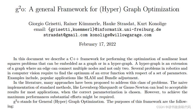
关于具体的g2o函数参数的含义,请参考g2o的简介、安装、使用说明和曲线拟合例程,讲的很详细,同时推荐阅读g2o的官方说明文件,是一个论文的形式:
3. 作业题T2
3.1 题意理解
此题比上面的题稍微复杂一些,主要不同在于本题的优化变量有多个,且边为二元边,均需要我们自行定义。
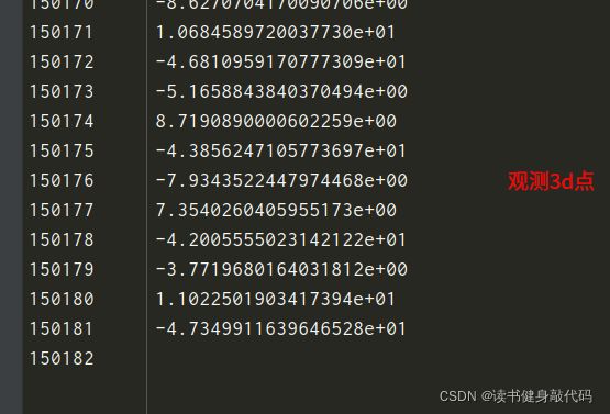
首先需要理解数据存储的方式:
- 相机号及观测部分
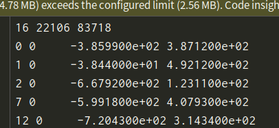
2. 相机位姿,焦距,畸变系数(即图中所说的camera,9维)
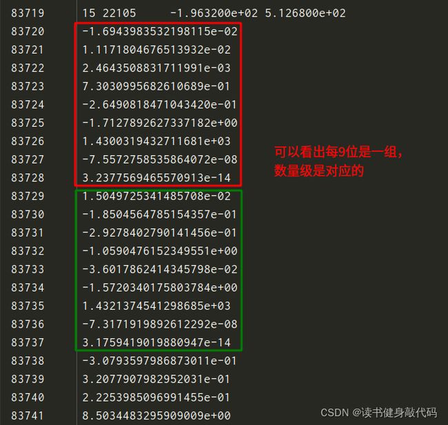
其中camera数据连续9个分别是:3维罗德里格斯旋转向量R,3维平移t,1维焦距f,2维径向畸变系数 k 1 , k 2 k_1,k_2 k1,k2(罗德里格斯旋转向量R需要进行指数运算转换为SO(3)才能将估计的3d点变换到相机系下)
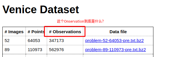
points应该是路标点的个数,路标点这里就是3d点,那么这个问题相当就是3d-2d的Pnp问题
这里的points是指实际上的路标点的个数,而Observations指的是在相机运动的过程中总共对这些路标点进行观测所获得的的观测点的个数,本来路标点就很多,又观测了很多次,就产生了很多的观测点。
理解了数据之后需要思考如何进行操作,核心仍然是定义自己的顶点和边
因为此题是将相机位姿和观测点同时放入BA进行优化,所以顶点有两种:
1.相机位姿相关的顶点(9维数据)
2.路标点对应的顶点(3维数据)。
边是二元边,连接这两种顶点。
3.2 代码讲解
借鉴SLAM14讲的代码,自己对其进行了理解。
完整代码:
//
// Created by wrk on 2022/3/28.
//
#include
vector<VertexPoseAndIntrinsics *> vertex_pose_intrinsics; //9维顶点临时变量
vector<VertexLandMark *> vertex_points; //3位landmark顶点临时变量
// 插入相机位姿顶点:3维罗德里格斯旋转向量R,3维平移t,1维焦距f,2维径向畸变系数
for (int i = 0; i < bal_problem.num_cameras(); ++i) {
VertexPoseAndIntrinsics *v = new VertexPoseAndIntrinsics();
double *camera = cameras + camera_block_size * i;
v->setId(i);
v->setEstimate(PoseAndIntrinsics(camera));
optimizer.addVertex(v);
vertex_pose_intrinsics.push_back(v);
}
// 插入路标点(这个)
for (int i = 0; i < bal_problem.num_points(); ++i)
{
VertexLandMark *v = new VertexLandMark();
double *point = points + point_block_size * i;
v->setId(i + bal_problem.num_cameras()); //从camera后面开始继续编号
v->setEstimate(Vector3d(point[0], point[1], point[2])); //对每个顶点设置估计的初值
// g2o在BA中需要手动设置待Marg的顶点,在这里设置就是要把路标点给marg掉
v->setMarginalized(true);
optimizer.addVertex(v);
vertex_points.push_back(v);
}
//
for(int i=0; i < bal_problem.num_observations(); ++i) //观测的数量,2个值算一组观测,所以取值的时候2*i
{
EdgeProjection *edge = new EdgeProjection;
edge->setVertex(0, vertex_pose_intrinsics[bal_problem.camera_index()[i]]);
edge->setVertex(1, vertex_points[bal_problem.point_index()[i]]);
edge->setMeasurement(Vector2d(observations[2*i+0], observations[2*i+1]));
edge->setInformation(Matrix2d::Identity()); //使用单位阵作为协方差矩阵
edge->setRobustKernel(new g2o::RobustKernelHuber());
optimizer.addEdge(edge);
}
optimizer.initializeOptimization();
optimizer.optimize(40);
//优化完成,保存
//更新相机位姿那9维数据
for(int i=0; i<bal_problem.num_cameras(); ++i)
{
double *camera = cameras + camera_block_size * i; //找camera地址
auto vertex = vertex_pose_intrinsics[i]; //取出优化后的9维顶点
auto estimate = vertex->estimate(); //读取估计值
estimate.set_to(camera); //保存至9维顶点
}
//更新三维点坐标
for(int i=0; i<bal_problem.num_points(); ++i)
{
double *point = points + point_block_size * i; //找三维点地址
auto vertex = vertex_points[i];
for(int k=0; k<3; ++k)
point[k] = vertex->estimate()[k];
}
}
int main(int argc, char** argv)
{
if (argc != 2) {
cout << "usage: BAL_g2o bal_data.txt" << endl;
return 1;
}
BALProblem bal_problem(argv[1]);
bal_problem.Normalize();
bal_problem.Perturb(0.1, 0.5, 0.5); //R,t,P标准差,加入噪声
bal_problem.WriteToPLYFile("initial_g2o.ply");
SolveBA(bal_problem);
bal_problem.WriteToPLYFile("final_g2o.ply");
return 0;
}
核心是SolveBA()函数(对数据进行读取和写入的common.cpp和common.h文件在这里略过)
先介绍自定义顶点和边:
位姿9维顶点,这里构造了一个struct用于存放9维位姿顶点的数据,很好理解:
struct PoseAndIntrinsics
{
    PoseAndIntrinsics() {}  //构造函数

    explicit PoseAndIntrinsics(double *data_addr)  //explicit之后只能用()进行初始化,不能用等号进行赋值
    {
        rotation = SO3d::exp(Vector3d(data_addr[0], data_addr[1], data_addr[2]));  //指数映射转换成SO3,罗德里格斯公式
        translation = Vector3d(data_addr[3], data_addr[4], data_addr[5]);
        focal = data_addr[6];
        k1 = data_addr[7];
        k2 = data_addr[8];
    }

    //将估计值放入内存
    void set_to(double *data_addr)
    {
        auto r = rotation.log();   //对数变换得se3
        for(int i=0;i<3;++i) data_addr[i] = r[i];
        for(int i=0;i<3;++i) data_addr[i+3] = translation[i];
        data_addr[6] = focal;
        data_addr[7] = k1;
        data_addr[8] = k2;
    }

    SO3d rotation;  //旋转SO3
    Vector3d translation;  //平移向量
    double focal = 0;  // 焦距
    double k1=0,k2=0;   //畸变系数
};
然后用这个数据结构定义9维位姿顶点
class VertexPoseAndIntrinsics: public g2o::BaseVertex<9, PoseAndIntrinsics>{
public:
    EIGEN_MAKE_ALIGNED_OPERATOR_NEW;  //重写new,使内存对齐
    VertexPoseAndIntrinsics() {}
    virtual void setToOriginImpl() override
    {
        _estimate = PoseAndIntrinsics();  //这就是要估计的对象:9维数据都需要被估计
    }
    // 估计更新
    virtual void oplusImpl(const double *update) override{
        _estimate.rotation = SO3d::exp(Vector3d(update[0], update[1], update[2])) * _estimate.rotation;
        _estimate.translation += Vector3d(update[3],update[4],update[5]);
        _estimate.focal += update[6];
        _estimate.k1 += update[7];
        _estimate.k2 += update[8];
    }
    //根据估计值投影一个点(估计的是相机系下的3d点)
    Vector2d project(const Vector3d &point){
        Vector3d pc = _estimate.rotation * point + _estimate.translation;
        pc = -pc / pc[2];
        /*这个畸变在数据官网有解释*/
        double r2 = pc.squaredNorm();
        double distortion = 1.0 + r2 * (_estimate.k1 + _estimate.k2 * r2);
        return Vector2d(_estimate.focal * distortion * pc[0],
                        _estimate.focal * distortion * pc[1]);
    }

    virtual bool read(istream &in) {}
    virtual bool write(ostream &out) const {}
};
初始化和更新都较为简单,主要是多了一个投影的过程
估计出来的路标点是3d的,将其投影到观测平面上才能计算误差,跟PnP的BA构建重投影误差是一样的,投影之后为2维向量。
3d路标顶点:
class VertexLandMark: public g2o::BaseVertex<3, Eigen::Vector3d>{
public:
    EIGEN_MAKE_ALIGNED_OPERATOR_NEW;  //重写new,使内存对齐

    VertexLandMark() {}

    virtual void setToOriginImpl() override
    {
        _estimate = Eigen::Vector3d(0,0,0);  //这就是要估计的对象:9维数据都需要被估计
    }

    virtual void oplusImpl(const double *update) override{
        _estimate += Eigen::Vector3d(update[0], update[1], update[2]);
    }

    virtual bool read(istream &in) {}

    virtual bool write(ostream &out) const {}
};
同样也是重写初始化和更新,没什么好说的。
二元边:
//传入参数参数2 :观测值(这里是3D点在像素坐标系下的投影坐标)的维度
//参数Vector :观测值类型,piexl.x,piexl.y
//参数VertexSBAPointXYZ:第一个顶点类型
//参数VertexSE3Expmap :第二个顶点类型
class EdgeProjection: public g2o::BaseBinaryEdge<2, Vector2d, VertexPoseAndIntrinsics, VertexLandMark>{
public:
    EIGEN_MAKE_ALIGNED_OPERATOR_NEW;

//    EdgeProjection(double x): BaseBinaryEdge(),
    virtual void computeError() override  //使用override显式地声明虚函数覆盖
    {
        VertexPoseAndIntrinsics * v0 = dynamic_cast<VertexPoseAndIntrinsics *>(_vertices[0]);  //读取位姿9维顶点
        VertexLandMark * v1 = dynamic_cast<VertexLandMark *>(_vertices[1]);  //读取位姿9维顶点
        // 利用估计的相机位姿和路标点的3d坐标将3d坐标重投影称像素坐标,与观测数据_measurement(实际上就是传进来的Vector2d)计算error,
        // 再由g2o自己计算雅可比,或者我么你自己定义那个2*6的雅可比
        auto proj = v0->project(v1->estimate());
        _error = proj - _measurement;    //为什么不是观测-预测??
    }
    // use numeric derivatives
    virtual bool read(istream &in) {}
    virtual bool write(ostream &out) const {}
};
这里我们只实现了误差的计算,没有进行雅可比的计算,雅可比交给g2o计算。
误差计算前面讲过将估计出的3d路标点结合相机位姿9维参数重投影到观测平面,变为2d像素坐标,如此即可计算误差_error,这里的误差定义为预测-观测,因为雅可比是g2o计算的,这跟之前的观测-预测计算出来的雅可比相差一个负号。
需要说明以下,这里的观测值_measurement其实就是初始化时传进来的Vector2d(_measurement就是这里的Vector2d),在后面添加边到图中的时候会看到。
回到SolveBA函数
读取起始地址和数据大小:
    const int point_block_size = bal_problem.point_block_size();
    const int camera_block_size = bal_problem.camera_block_size();  //位姿,内参,畸变系数
    double *points = bal_problem.mutable_points();      //  观测点的起始地址
    double *cameras = bal_problem.mutable_cameras();    //  camera参数的起始地址
插入顶点和边到图中,有了上面对顶点和边的介绍,这部分会比较好理解:
    // 5.定义图的顶点和边,添加到稀疏优化器中
    const double *observations = bal_problem.observations();  //这个观测值就是前面的4维数据
    vector<VertexPoseAndIntrinsics *> vertex_pose_intrinsics;  //9维顶点临时变量
    vector<VertexLandMark *> vertex_points;  //3位landmark顶点临时变量
    // 插入相机位姿顶点:3维罗德里格斯旋转向量R,3维平移t,1维焦距f,2维径向畸变系数
    for (int i = 0; i < bal_problem.num_cameras(); ++i) {
        VertexPoseAndIntrinsics *v = new VertexPoseAndIntrinsics();
        double *camera = cameras + camera_block_size * i;
        v->setId(i);
        v->setEstimate(PoseAndIntrinsics(camera));
        optimizer.addVertex(v);
        vertex_pose_intrinsics.push_back(v);
    }
    // 插入路标点
    for (int i = 0; i < bal_problem.num_points(); ++i)
    {
        VertexLandMark *v = new VertexLandMark();
        double *point = points + point_block_size * i;
        v->setId(i + bal_problem.num_cameras());  //从camera后面开始继续编号
        v->setEstimate(Vector3d(point[0], point[1], point[2]));  //对每个顶点设置估计的初值
        // g2o在BA中需要手动设置待Marg的顶点,在这里设置就是要把路标点给marg掉
        v->setMarginalized(true);
        optimizer.addVertex(v);
        vertex_points.push_back(v);
    }
    // 插入边
    for(int i=0; i < bal_problem.num_observations(); ++i)  //观测的数量,2个值算一组观测,所以取值的时候2*i
    {
        EdgeProjection *edge = new EdgeProjection;
        edge->setVertex(0, vertex_pose_intrinsics[bal_problem.camera_index()[i]]);
        edge->setVertex(1, vertex_points[bal_problem.point_index()[i]]);
        edge->setMeasurement(Vector2d(observations[2*i+0], observations[2*i+1]));
        edge->setInformation(Matrix2d::Identity());  //使用单位阵作为协方差矩阵
        edge->setRobustKernel(new g2o::RobustKernelHuber());
        optimizer.addEdge(edge);
    }
可以看到我们为了使用H的稀疏性加快求解速度,对3d路标顶点设置了边缘化flag:
v->setMarginalized(true);
这里对于边缘化的理解就更具象化了一些。
边在初始化时设置了setMeasurement,用于计算_error
优化完成之后就是保存所有相机位姿9维数据和所有路标的3维数据
    optimizer.initializeOptimization();
    optimizer.optimize(40);

    //优化完成,保存
    //更新相机位姿那9维数据
    for(int i=0; i<bal_problem.num_cameras(); ++i)
    {
        double *camera = cameras + camera_block_size * i;  //找camera地址
        auto vertex = vertex_pose_intrinsics[i];  //取出优化后的9维顶点
        auto estimate = vertex->estimate();  //读取估计值
        estimate.set_to(camera);    //保存至9维顶点
    }
    //更新三维点坐标
    for(int i=0; i<bal_problem.num_points(); ++i)
    {
        double *point = points + point_block_size * i;  //找三维点地址
        auto vertex = vertex_points[i];
        for(int k=0; k<3; ++k)
            point[k] = vertex->estimate()[k];
    }
不得不说,高博这个代码写的是真的秒,数据结构定义的真的好。
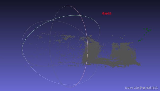
运行了例程的数据,手写的感觉就是不一样,整个代码被我玩弄于鼓掌(狗头):
4. 作业题T3
主要参考博客1和博客2
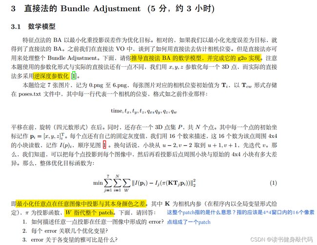
4.1 题目
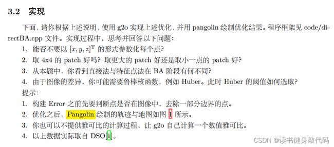
4.2 解答
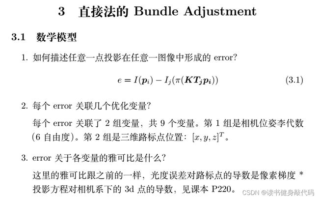
之前定性地以为直接法只是优化相机的位姿,对路标点不进行优化,但实际上直接法关联的变量就已经同时包含了位姿和路标点:
e = I 1 ( p 1 ) − I 2 ( p 2 ) = I 1 ( 1 Z 1 K P ) − I 2 ( 1 Z 2 K ( T P ) 1 : 3 ) e=I_1(\bm p_1)-I_2(\bm p_2)=I_1(\frac{1}{Z_1}\bm{KP})-I_2(\frac{1}{Z_2}\bm{K}(\bm{TP})_{1:3}) e=I1(p1)−I2(p2)=I1(Z11KP)−I2(Z21K(TP)1:3)
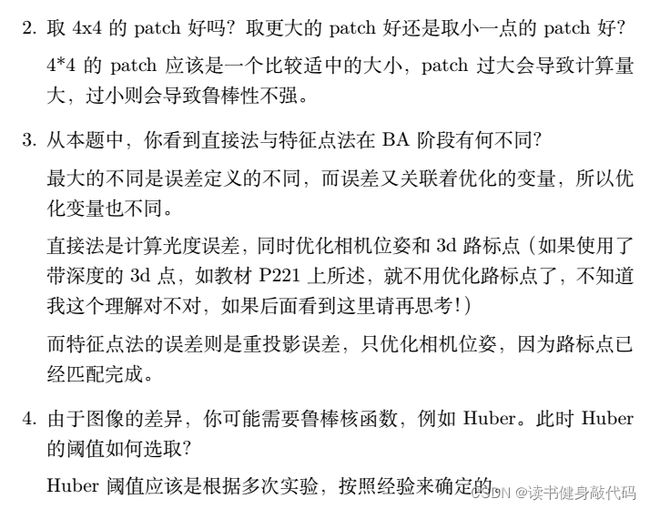
教材P221说了因为使用的是带深度的数据而非单目数据,所以不需要对路标点进行优化,路标点的3d坐标是已知的,但是本题我们只是知道3d点的初始坐标,需要对其进行优化,所以这里需要引入对路标点的雅可比,在求解部分会看到。
4.3 整体代码
整体代码如Listing2所示:
//
// Created by xiang on 1/4/18.
// this program shows how to perform direct bundle adjustment
//
#include ();
// DirectBlock *solver_ptr = new DirectBlock(linearSolver);
auto solver = new g2o::OptimizationAlgorithmLevenberg(g2o::make_unique<DirectBlock>(g2o::make_unique<LinearSolverType>()));
g2o::SparseOptimizer optimizer;
optimizer.setAlgorithm(solver);
optimizer.setVerbose(true);
// TODO add vertices, edges into the graph optimizer
vector<g2o::VertexSBAPointXYZ *> vertex_points; //3位landmark顶点临时变量
vector<VertexSophus *> vertex_pose; //pose顶点临时变量
// START YOUR CODE HERE
//插入路标顶点
for(int i=0; i<points.size(); ++i)
{
g2o::VertexSBAPointXYZ *v = new g2o::VertexSBAPointXYZ;
v->setId(i);
v->setEstimate(points[i]);
v->setMarginalized(true); //设置边缘化路标点
optimizer.addVertex(v);
vertex_points.push_back(v);
}
//插入位姿顶点
for(int i=0; i<poses.size(); ++i)
{
VertexSophus *v = new VertexSophus();
v->setId(i + points.size());
v->setEstimate(poses[i]);
optimizer.addVertex(v);
vertex_pose.push_back(v);
}
//插入边
for(int c=0; c<poses.size(); ++c)
for(int p=0; p<points.size(); ++p)
{
EdgeDirectProjection *edge = new EdgeDirectProjection(color[p], images[c]); //每个图中的每个点都插入到优化图中,都有一条边
//先point后pose
edge->setVertex(0, dynamic_cast<g2o::VertexSBAPointXYZ *>(optimizer.vertex(p)));
edge->setVertex(1, dynamic_cast<VertexSophus *>(optimizer.vertex(points.size()+c)));
// edge->setMeasurement(Vector16d );
// 信息矩阵可直接设置为 error_dim*error_dim 的单位阵
edge->setInformation(Eigen::Matrix<double, 16, 16>::Identity());
// 设置Huber核函数,减小错误点影响,加强鲁棒性
g2o::RobustKernelHuber *rk = new g2o::RobustKernelHuber;
rk->setDelta(1.0); //A squared error above delta^2 is considered as outlier in the data
edge->setRobustKernel(rk);
optimizer.addEdge(edge);
}
// END YOUR CODE HERE
Draw(poses, points, string("before"));
// perform optimization
optimizer.initializeOptimization(0);
optimizer.optimize(100);
// TODO fetch data from the optimizer
// START YOUR CODE HERE
for(int c=0; c<poses.size(); ++c)
for(int p=0; p<points.size(); ++p)
{
points[p] = dynamic_cast<g2o::VertexSBAPointXYZ *>(optimizer.vertex(p))->estimate();
poses[c] = dynamic_cast<VertexSophus *>(optimizer.vertex(points.size()+c))->estimate();
}
// END YOUR CODE HERE
// plot the optimized points and poses
Draw(poses, points, "after");
// 看看这数据有没有什么不一样的?怎么看优化的对不对?
// delete color data
for (auto &c: color) delete[] c;
return 0;
}
void Draw(const VecSE3 &poses, const VecVec3d &points, string title) {
if (poses.empty() || points.empty()) {
cerr << "parameter is empty!" << endl;
return;
}
// create pangolin window and plot the trajectory
pangolin::CreateWindowAndBind(title, 1024, 768);
glEnable(GL_DEPTH_TEST);
glEnable(GL_BLEND);
glBlendFunc(GL_SRC_ALPHA, GL_ONE_MINUS_SRC_ALPHA);
pangolin::OpenGlRenderState s_cam(
pangolin::ProjectionMatrix(1024, 768, 500, 500, 512, 389, 0.1, 1000),
pangolin::ModelViewLookAt(0, -0.1, -1.8, 0, 0, 0, 0.0, -1.0, 0.0)
);
pangolin::View &d_cam = pangolin::CreateDisplay()
.SetBounds(0.0, 1.0, pangolin::Attach::Pix(175), 1.0, -1024.0f / 768.0f)
.SetHandler(new pangolin::Handler3D(s_cam));
while (pangolin::ShouldQuit() == false) {
glClear(GL_COLOR_BUFFER_BIT | GL_DEPTH_BUFFER_BIT);
d_cam.Activate(s_cam);
glClearColor(0.0f, 0.0f, 0.0f, 0.0f);
// draw poses
float sz = 0.1;
int width = 640, height = 480;
for (auto &Tcw: poses) {
glPushMatrix();
Sophus::Matrix4f m = Tcw.inverse().matrix().cast<float>();
glMultMatrixf((GLfloat *) m.data());
glColor3f(1, 0, 0);
glLineWidth(2);
glBegin(GL_LINES);
glVertex3f(0, 0, 0);
glVertex3f(sz * (0 - cx) / fx, sz * (0 - cy) / fy, sz);
glVertex3f(0, 0, 0);
glVertex3f(sz * (0 - cx) / fx, sz * (height - 1 - cy) / fy, sz);
glVertex3f(0, 0, 0);
glVertex3f(sz * (width - 1 - cx) / fx, sz * (height - 1 - cy) / fy, sz);
glVertex3f(0, 0, 0);
glVertex3f(sz * (width - 1 - cx) / fx, sz * (0 - cy) / fy, sz);
glVertex3f(sz * (width - 1 - cx) / fx, sz * (0 - cy) / fy, sz);
glVertex3f(sz * (width - 1 - cx) / fx, sz * (height - 1 - cy) / fy, sz);
glVertex3f(sz * (width - 1 - cx) / fx, sz * (height - 1 - cy) / fy, sz);
glVertex3f(sz * (0 - cx) / fx, sz * (height - 1 - cy) / fy, sz);
glVertex3f(sz * (0 - cx) / fx, sz * (height - 1 - cy) / fy, sz);
glVertex3f(sz * (0 - cx) / fx, sz * (0 - cy) / fy, sz);
glVertex3f(sz * (0 - cx) / fx, sz * (0 - cy) / fy, sz);
glVertex3f(sz * (width - 1 - cx) / fx, sz * (0 - cy) / fy, sz);
glEnd();
glPopMatrix();
}
// points
glPointSize(2);
glBegin(GL_POINTS);
for (size_t i = 0; i < points.size(); i++) {
glColor3f(0.0, points[i][2]/4, 1.0-points[i][2]/4);
glVertex3d(points[i][0], points[i][1], points[i][2]);
}
glEnd();
pangolin::FinishFrame();
usleep(5000); // sleep 5 ms
}
}
4.4 顶点和边的定义
这里对代码进行一些理解,核心部分有定义自己的边和雅可比的计算,可以和之前前端中的直接法进行类比。
- 前面的读取位姿,读取路标点,读取图片部分较为简单,此处略过
- 构建g2o问题的前4步也略过,之前讲过
- 定义顶点和边,并添加到图中
顶点和边的定义:
// g2o vertex that use sophus::SE3 as pose  自定义位姿顶点,数据类型是SE3d
class VertexSophus : public g2o::BaseVertex<6, Sophus::SE3d> {
public:
    EIGEN_MAKE_ALIGNED_OPERATOR_NEW

    VertexSophus() {}

    ~VertexSophus() {}


    virtual void setToOriginImpl() {
        _estimate = Sophus::SE3d();
    }

    //根据估计值投影一个点(估计的是相机系下的3d点)
    Vector2f project(const Vector3d &point)
    {
        //KTP 读取SE(3),转换,投影为像素坐标,访问像素灰度值计算光度误差
        Sophus::SE3d Tcw(estimate());
        Vector3d point_cam3d = Tcw * point;
        float u = fx * point_cam3d[0]/point_cam3d[2] + cx;
        float v = fy * point_cam3d[1]/point_cam3d[2] + cy;
        return Vector2f(u,v);
    }

    //更新
    virtual void oplusImpl(const double *update_) {
        //计算se(3),再由se(3)为SE(3)
        Eigen::Map<const Eigen::Matrix<double, 6, 1>> update(update_);
        //保存估计值,相当于_estimate = Sophus::SE3d::exp(update) * _estimate;
        setEstimate(Sophus::SE3d::exp(update) * estimate());
    }

    virtual bool read(std::istream &is) {}

    virtual bool write(std::ostream &os) const {}
};

// TODO edge of projection error, implement it
// 16x1 error, which is the errors in patch   16个像素点的光度差之和
typedef Eigen::Matrix<double,16,1> Vector16d;
class EdgeDirectProjection : public g2o::BaseBinaryEdge<16, Vector16d, g2o::VertexSBAPointXYZ, VertexSophus>  //一个是SBA的XYZ自带边,一个是自定义的边
        {
public:
    EIGEN_MAKE_ALIGNED_OPERATOR_NEW;

    //边构造函数
    EdgeDirectProjection(float *color, cv::Mat &target) {
        this->origColor = color;
        this->targetImg = target;
    }

    ~EdgeDirectProjection() {}

    virtual void computeError() override {
        // TODO START YOUR CODE HERE
        // compute projection error ...
        //projected = KTP  需要使用SE(3)
        g2o::VertexSBAPointXYZ* vertexPw = static_cast<g2o::VertexSBAPointXYZ *>(_vertices[0]);
        VertexSophus* vertexTcw = static_cast<VertexSophus *>(_vertices[1]);
        Vector2f proj = vertexTcw->project(vertexPw->estimate());
        //判断是否越界,若越界,则将error该位置1,并setLevel(1)不知道啥意思,是记录好坏的吗?
        if(proj[0]<-2 || proj[0]+2>targetImg.cols || proj[1]<-2 || proj[1]+2>targetImg.rows)
        {
            this->setLevel(1);  //设置level为1,标记为outlier,下次不再对该边进行优化
            for(int i=0; i<16; ++i)  _error[i] = 0;  //_error是16*1的向量
        }
        else{
            for(int i=-2; i<2;++i){
                for(int j=-2; j<2; ++j){
                	//实际上是计算patch中第几个,num=4*(x+2)+(y+2)=4x+y+10
                    int num = 4 * i + j + 10;
                    //_measurement是一个16*1的向量,所以_error也是16*1
                    _error[num] = origColor[num] - GetPixelValue(targetImg, proj[0]+i, proj[1]+j);
                }
            }
        }
        // END YOUR CODE HERE
    }
    // Let g2o compute jacobian for you , no, I will carry you, boy~
    virtual void linearizeOplus() override
    {
        //分别计算3d点和李代数的雅可比
//        J_I2u
//        J_uq
//        J_qxi
        if(level()==1)
        {
            _jacobianOplusXi = Eigen::Matrix<double, 16, 3>::Zero();  //因为_error是(D,1)的,D=16是4*4的patch,所以对第一个顶点的雅可比就是16*2*2*3=16*3的
            _jacobianOplusXj = Eigen::Matrix<double, 16, 6>::Zero();  //同理,对第二个顶点(李代数顶点)的雅可比是16*2*2*3*3*6=16*6的
            return;
        }

        g2o::VertexSBAPointXYZ *vertexPw = static_cast<g2o::VertexSBAPointXYZ *> (_vertices[0]);
        VertexSophus *vertexTcw = static_cast<VertexSophus *> (_vertices[1]);
        Vector2f proj = vertexTcw->project(vertexPw->estimate());

        double X = vertexPw->estimate()[0], Y = vertexPw->estimate()[1], Z = vertexPw->estimate()[2];
        double inv_z = 1.0 / Z, inv_z2 = inv_z * inv_z;  //cur中的3D坐标X'Y'Z'
        float u = proj[0], v = proj[1];

        Eigen::Matrix<double,1,2> J_I2u;    //像素梯度
        Eigen::Matrix<double,2,3> J_uq;     //投影方程对3d点导数
        Eigen::Matrix<double,3,6> J_qxi = Eigen::Matrix<double,3,6>::Zero();    //3d点对李代数导数

        J_uq(0,0) = fx * inv_z;
        J_uq(0,1) = 0;
        J_uq(0,2) = -(fx*X) * inv_z2;
        J_uq(1,0) = 0;
        J_uq(1,1) = fy * inv_z;
        J_uq(1,2) = -fy * Y * inv_z2;

        //这个矩阵见P187笔记[I| -P'^]
        J_qxi(0,0) = 1;
        J_qxi(0,4) = Z;
        J_qxi(0,5) = -Y;
        J_qxi(1,1) = 1;
        J_qxi(1,3) = -Z;
        J_qxi(1,5) = X;
        J_qxi(2,2) = 1;
        J_qxi(2,3) = -Y;
        J_qxi(2,4) = -X;

        for(int x=-2; x<2; ++x)
            for(int y=-2; y<2; ++y)
            {
                //这num到底是什么意思???实际上是计算patch中第几个,num=4*(x+2)+(y+2)=4x+y+10
                int num = 4 * x + y + 10;

                //中心差分计算像素梯度
                J_I2u(0,0) = (1.0 / 2) * (GetPixelValue(targetImg, u+1+x, v+y)-GetPixelValue(targetImg, u-1+x, v+y));
                J_I2u(0,1) = (1.0 / 2) * (GetPixelValue(targetImg, u+x, v+1+y)-GetPixelValue(targetImg, u+x, v-1+y));

                /********为什么还要乘以一个变换矩阵?******/
//                _jacobianOplusXi.block<1, 3>(num, 0) = -J_I2u * J_uq * vertexTcw->estimate().rotationMatrix();
                _jacobianOplusXi.block<1, 3>(num, 0) = -J_I2u * J_uq ;

                _jacobianOplusXj.block<1, 6>(num, 0) = -J_I2u * J_uq * J_qxi;

            }
    }

    virtual bool read(istream &in) {}

    virtual bool write(ostream &out) const {}

private:
    cv::Mat targetImg;  // the target image
    float *origColor = nullptr;   // 16 floats, the color of this point
};
理解问题:待优化变量是3d路标点和相机位姿,误差定义为所有patch中的点向所有图片中像素点重投影的误差之和。所以顶点有两种:
-
3d路标点(3维):这里使用g2o自带的顶点类型
g2o::VertexSBAPointXYZ即可,需要在CMakeLists.txt中添加target_link_libraries(XXX g2o_types_sba),否则会报错。 -
相机位姿(SE3,由于我们使用的是李代数进行求导,所以顶点数据类型是6维向量,表示李代数,输出的估计类型是SE(3),在内部进行指数变换)
VertexSophus这里主要进行了一个投影操作project,根据估计的pose和3d点坐标投影到像素平面,便于计算重投影误差。
边是二元边,和T3一样,连接了上述的两种顶点,这里的误差维度是根据patch取的,patch中共4*4=16个点,所以误差为16维。这里核心是计算误差和雅可比
- 计算误差
    virtual void computeError() override {
        // TODO START YOUR CODE HERE
        // compute projection error ...
        //projected = KTP  需要使用SE(3)
        g2o::VertexSBAPointXYZ* vertexPw = static_cast<g2o::VertexSBAPointXYZ *>(_vertices[0]);
        VertexSophus* vertexTcw = static_cast<VertexSophus *>(_vertices[1]);
        Vector2f proj = vertexTcw->project(vertexPw->estimate());
        //判断是否越界,若越界,则将error该位置1
        if(proj[0]<-2 || proj[0]+2>targetImg.cols || proj[1]<-2 || proj[1]+2>targetImg.rows)
        {
            this->setLevel(1);  //设置level为1,标记为outlier,下次不再对该边进行优化
            for(int i=0; i<16; ++i)  _error[i] = 0;  //_error是16*1的向量
        }
        else{
            for(int i=-2; i<2;++i){
                for(int j=-2; j<2; ++j){
                    //实际上是计算patch中第几个,num=4*(x+2)+(y+2)=4x+y+10
                    int num = 4 * i + j + 10;
                    //_measurement是一个16*1的向量,所以_error也是16*1
                    _error[num] = origColor[num] - GetPixelValue(targetImg, proj[0]+i, proj[1]+j);
                }
            }
        }
        // END YOUR CODE HERE
    }
误差计算和前端的BA思路类似,取出g2o::VertexSBAPointXYZ的估计值,使用VertexSophus进行重投影,这里需要判断重投影之后的坐标是否越界,如果越界则认为是outlier,处理方法是this->setLevel(1);
在计算雅可比前进行level的判断,g2o中使用level判断是否是outlier,若为level==1则不计算雅可比,直接置为0。
- 计算雅可比
    virtual void linearizeOplus() override
    {
        //分别计算3d点和李代数的雅可比
        //J_I2u
        //J_uq
        //J_qxi
        if(level()==1)
        {
            _jacobianOplusXi = Eigen::Matrix<double, 16, 3>::Zero();  //因为_error是(D,1)的,D=16是4*4的patch,所以对第一个顶点的雅可比就是16*2*2*3=16*3的
            _jacobianOplusXj = Eigen::Matrix<double, 16, 6>::Zero();  //同理,对第二个顶点(李代数顶点)的雅可比是16*2*2*3*3*6=16*6的
            return;
        }

        g2o::VertexSBAPointXYZ *vertexPw = static_cast<g2o::VertexSBAPointXYZ *> (_vertices[0]);
        VertexSophus *vertexTcw = static_cast<VertexSophus *> (_vertices[1]);
        Vector2f proj = vertexTcw->project(vertexPw->estimate());

        double X = vertexPw->estimate()[0], Y = vertexPw->estimate()[1], Z = vertexPw->estimate()[2];
        double inv_z = 1.0 / Z, inv_z2 = inv_z * inv_z;  //cur中的3D坐标X'Y'Z'
        float u = proj[0], v = proj[1];

        Eigen::Matrix<double,1,2> J_I2u;    //像素梯度
        Eigen::Matrix<double,2,3> J_uq;     //投影方程对3d点导数
        Eigen::Matrix<double,3,6> J_qxi = Eigen::Matrix<double,3,6>::Zero();    //3d点对李代数导数

        J_uq(0,0) = fx * inv_z;
        J_uq(0,1) = 0;
        J_uq(0,2) = -(fx*X) * inv_z2;
        J_uq(1,0) = 0;
        J_uq(1,1) = fy * inv_z;
        J_uq(1,2) = -fy * Y * inv_z2;

        //这个矩阵见P187笔记[I| -P'^]
        J_qxi(0,0) = 1;
        J_qxi(0,4) = Z;
        J_qxi(0,5) = -Y;
        J_qxi(1,1) = 1;
        J_qxi(1,3) = -Z;
        J_qxi(1,5) = X;
        J_qxi(2,2) = 1;
        J_qxi(2,3) = -Y;
        J_qxi(2,4) = -X;

        for(int x=-2; x<2; ++x)
            for(int y=-2; y<2; ++y)
            {
                //实际上是计算patch中第几个,num=4*(x+2)+(y+2)=4x+y+10
                int num = 4 * x + y + 10;

                //中心差分计算像素梯度
                J_I2u(0,0) = (1.0 / 2) * (GetPixelValue(targetImg, u+1+x, v+y)-GetPixelValue(targetImg, u-1+x, v+y));
                J_I2u(0,1) = (1.0 / 2) * (GetPixelValue(targetImg, u+x, v+1+y)-GetPixelValue(targetImg, u+x, v-1+y));

                /********还要乘以一个变换矩阵******/
                _jacobianOplusXi.block<1, 3>(num, 0) = -J_I2u * J_uq * vertexTcw->estimate().rotationMatrix();
                _jacobianOplusXj.block<1, 6>(num, 0) = -J_I2u * J_uq * J_qxi;

            }
    }
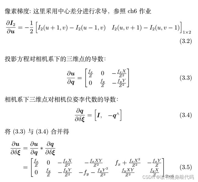
这里的雅克比计算可以参照上面的数学推导,主要是3块雅可比的计算,J_I2u,J_uq,J_qxi,分别是像素梯度,投影方程对3d点导数,3d点对李代数导数。
其中像素梯度需要结合patch来计算,使用中心差分来计算,在第6讲作业中讲过了。
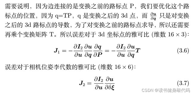
这里雅可比是向量对向量求导,分别根据原则1和原则2进行计算,得到_jacobianOplusXi是 16 × 3 16\times 3 16×3的,_jacobianOplusXj是 16 × 6 16\times 6 16×6的,计算时使用了分块计算的方法每个小块是 1 × 3 1\times 3 1×3或者 1 × 6 1\times 6 1×6的,每个小块跟之前直接法里面的雅可比的计算是相同的。
需要说明一下这里对3d点的雅可比是对变换之前的点P求导的,所以还需要乘以一个SE(3)变换矩阵。
4.5 插入顶点和边
这部分比较简单:
    // START YOUR CODE HERE
    //插入路标顶点
    for(int i=0; i<points.size(); ++i)
    {
        g2o::VertexSBAPointXYZ *v = new g2o::VertexSBAPointXYZ;
        v->setId(i);
        v->setEstimate(points[i]);
        v->setMarginalized(true);   //设置边缘化路标点
        optimizer.addVertex(v);
        vertex_points.push_back(v);
    }
    //插入位姿顶点
    for(int i=0; i<poses.size(); ++i)
    {
        VertexSophus *v = new VertexSophus();
        v->setId(i + points.size());
        v->setEstimate(poses[i]);
        optimizer.addVertex(v);
        vertex_pose.push_back(v);
    }

    //插入边
    for(int c=0; c<poses.size(); ++c)
        for(int p=0; p<points.size(); ++p)
        {
            EdgeDirectProjection *edge = new EdgeDirectProjection(color[p], images[c]);  //每个图中的每个点都插入到优化图中,都有一条边
            //先point后pose
            edge->setVertex(0, dynamic_cast<g2o::VertexSBAPointXYZ *>(optimizer.vertex(p)));
            edge->setVertex(1, dynamic_cast<VertexSophus *>(optimizer.vertex(points.size()+c)));
//            edge->setMeasurement(Vector16d );
            // 信息矩阵可直接设置为 error_dim*error_dim 的单位阵
            edge->setInformation(Eigen::Matrix<double, 16, 16>::Identity());
            // 设置Huber核函数,减小错误点影响,加强鲁棒性
            g2o::RobustKernelHuber *rk = new g2o::RobustKernelHuber;
            rk->setDelta(1.0);  //A squared error above delta^2 is considered as outlier in the data
            edge->setRobustKernel(rk);
            optimizer.addEdge(edge);
        }
    // END YOUR CODE HERE
4.6 优化,读取优化之后的poses和points,绘图
Draw(poses, points, string("before"));

// perform optimization
optimizer.initializeOptimization(0);
optimizer.optimize(100);

// TODO fetch data from the optimizer
// START YOUR CODE HERE
for(int c=0; c<poses.size(); ++c)
    for(int p=0; p<points.size(); ++p)
    {
        points[p] = dynamic_cast<g2o::VertexSBAPointXYZ *>(optimizer.vertex(p))->estimate();
        poses[c] = dynamic_cast<VertexSophus *>(optimizer.vertex(points.size()+c))->estimate();
    }

// END YOUR CODE HERE

// plot the optimized points and poses
Draw(poses, points, "after");
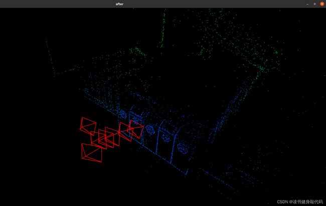
4.7 结果展示
优化前的点云图如图3.1所示,优化后的如图3.2所示
图3.1
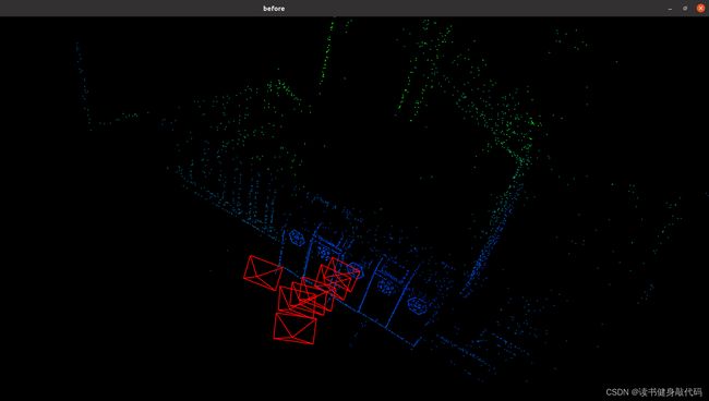
图3.2
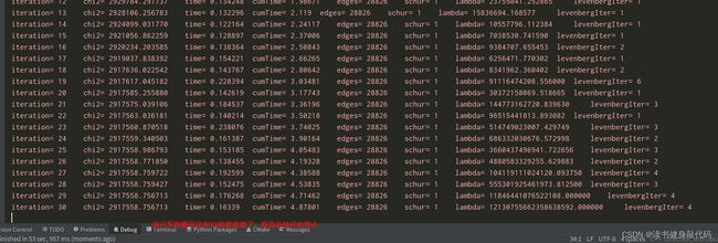
实验了自己写的雅可比和让g2o自己写雅可比的性能对比,自己写的雅可比优化速度要快一些,且边的代价也要小一些,对比分别如图3.3和3.4所示:


