学习笔记3
3.1 图像的透视变换
//获得从原图到目标效果的变换矩阵
Mat getPerspectiveTransform(const Point2f src[], const Point2f dst[]);
//进行透视变换
//获得从原图到目标效果的变换矩阵
Mat getPerspectiveTransform(const Point2f src[], const Point2f dst[]);
//进行透视变换
void warpPerspective( InputArray src, OutputArray dst,
                                   InputArray M, Size dsize);
例:
#include
#include
#include
#include
using namespace std;
using namespace cv;
float w = 250, h = 350;//图片大小
Mat matrix, imgWarp;
void main() {
	//图片用画图打开,在屏幕左下角会显示点的坐标
	string path = "D:/本机图片/test.jpg";
	Mat img = imread(path);
	//src[4]表示的是需要变换的部分在原图像中的坐标分别是左上、右上、左下和右下角
	//dst[4]表示的是矫正后图像的坐标,顺序同上,w和h表示需要的宽高
	Point2f src[4] = { {0,0},{771,190},{405,395},{674,457} };
	Point2f dst[4] = { {0.0f,0.0f},{w,0.0f},{0.0f,h},{w,h} };
	//根据定义的大小,计算变换矩阵 matrix
	matrix = getPerspectiveTransform(src, dst);
	//利用已经明确的matrix获得透视变换后的图像imgWarp
	warpPerspective(img, imgWarp, matrix, Point(w, h));
	//将提取的坐标绘制到图像上方便观察是否找对点
	for (int i = 0; i < 4; i++) {
		circle(img, src[i], 10, Scalar(0, 0, 255), FILLED);
	}
	imshow("Image", img);
	imshow("Image Warp", imgWarp);
	waitKey(0);//在此处等待
}
3.2 颜色检测
使用 OpenCV 提供的颜色检测方法,对图片中的颜色进行提取,使用的函数如下:
//转换颜色空间,便于检测
void cvtColor( InputArray src, OutputArray dst, int code, int dstCn = 0 );
//颜色检测
void inRange(InputArray src, InputArray lowerb,
                          InputArray upperb, OutputArray dst);
例:
#include
#include
#include
#include
using namespace std;
using namespace cv;
//h s v 分别对应 hue 色调; saturation 饱和度;value 亮度
int hmin = 0, smin = 0, vmin = 0;
int hmax = 179, smax = 168, vmax = 56;
void main() {
    string path = "Resources/1.png";
    Mat img=imread(path);
    Mat imgHSV,outImg;
    cvtColor(img, imgHSV, COLOR_BGR2HSV);//转换图像到HSV空间,在其中查找颜色更加容易
    //定义颜色的上下界,是以一个向量的形式呈现的,每个向量都有hsv三个值
    Scalar lower(hmin, smin, vmin);
    Scalar upper(hmax, smax, vmax);
    //检测在lower 和 upper 之间的颜色,并输出在outImg 上
    inRange(imgHSV, lower, upper, outImg);
    imshow("Image", img);
    imshow("Image HSV", imgHSV);
    imshow("Image mask", outImg);
    waitKey(0);
}
hmin smin vmin 以及 hmax smax vmax 是我们事先给定的一些数值,代表了对应的颜色,由于就算是同一种颜色,在一张照片中,由于光照、阴影等多种因素的影响,其数值也会不同,所以想要检测某种颜色时,需要使用一个范围来尽可能的检测该种颜色的全部表现。
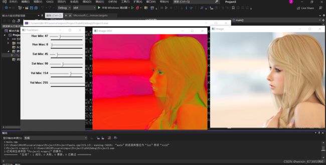
lower 和 upper 中的这些值,可以通过添加 Trackbar 来动态实时调整其数值,并观察效果.
例
int hmin = 0, smin = 0, vmin = 0;
int hmax = 179, smax = 255, vmax = 255;
void main() {
    string path = "Resources/1.png";
    Mat img=imread(path);
    Mat imgHSV,mask;
    cvtColor(img, imgHSV, COLOR_BGR2HSV);
    //创建一个用于放置跟踪栏的窗口
    namedWindow("Trackbars", (640, 200));//(640,200)是尺寸
    //运行时,把3个min的都移到最小值,把3个max的都移到最大值,然后移动使其保持为白色
    //添加Trackbar
    createTrackbar("Hue Min", "Trackbars", &hmin, 179);
    createTrackbar("Hue Max", "Trackbars", &hmax, 179);
    createTrackbar("Sat Min", "Trackbars", &smin, 255);
    createTrackbar("Sat Max", "Trackbars", &smax, 255);
    createTrackbar("Val Min", "Trackbars", &vmin, 255);
    createTrackbar("Val Max", "Trackbars", &vmax, 255);

    while (true) {
        //检查数组元素是否位于其他两个数组的元素之间。
        //imgHSV为输入图像,mask为输出图像
        Scalar lower(hmin, smin, vmin);
        Scalar upper(hmax, smax, vmax);
        inRange(imgHSV, lower, upper, mask);
        imshow("Image", img);
        imshow("Image HSV", imgHSV);
        imshow("Image mask", mask);
        waitKey(1);//延时1ms
    }
}
可以得到如下的结果:
3.3 形状、轮廓检测
通过 OpenCV 提供的函数进行,简单的形状检测,并给检测出来的形状添加 boundingbox。整个过程的流程如下图所示:
![]()
3.3.1 图像的预处理
图像的预处理阶段,实质上就是通过灰度处理、高斯模糊、边缘检测然后再加粗边缘得到一个二值化的图像,便于边界检测函数进行检测。预处理函数:
Mat imgGray, imgBlur, imgCanny, imgDil;
cvtColor(img, imgGray, COLOR_BGR2GRAY);//cvt是convert的缩写,将图像从一种颜色空间转换为另一种颜色空间。
GaussianBlur(imgGray, imgBlur,Size(3,3),3,0);//使用高斯滤波器模糊图像。该函数将源图像与指定的高斯核进行卷积,Size(7,7)是核大小,数字越大越模糊
Canny(imgBlur, imgCanny, 25, 75);//边缘检测,阈值1,2可调,目的:显示更多的边缘
Mat kernel = getStructuringElement(MORPH_RECT, Size(3, 3));//创建一个核,增加Size(只能是奇数)会扩张/侵蚀更多
dilate(imgCanny, imgDil, kernel);//扩张边缘(增加边缘厚度)
预处理前后的图片
3.3.2 形状检测
图片预处理之后,进行形状检测了,需要使用到以下的函数:
void findContours( InputArray image, OutputArrayOfArrays contours,
                              OutputArray hierarchy, int mode,
                              int method);
各个参数的含义:
InputArray image :预处理之后得到的二值化图像(8bit 单通道图像);
OutputArrayOfArrays contours:函数的输出,它是 std::vector
OutputArray hierarchy:该变量存储了 contours 中对应元素的相关拓扑信息,其类型为 std::vector
int mode,int method :这里的 mode 和 method 是指形状检测的模式和方法,OpenCV 提供了多种的模式和方法。
所以,为了使用 findContours (), 我们先要定义其需要的参数。
vector> contours;
vector hierarchy;
findContours(imgDil, contours, hierarchy, RETR_EXTERNAL, CHAIN_APPROX_SIMPLE);
//获得提取的轮廓以后,我们可以通过下面的函数将检测到的轮廓在图上表示出来
//其中 -1 表示把全部检测到的轮廓都输出, 向量Scalar(255, 0, 255) 表示颜色, 2 表示轮廓厚度
drawContours(img, contours, -1, Scalar(255, 0, 255), 2);
得到的效果如下图所示:
3.3.3 添加 Boundingbox
为了给检测到的形状添加边界框,我们首先需要检测其角点,检测到角点以后,还可以根据角点的个数来判断具体是什么形状,例如三角形一般是 3 个角点,矩形一般是 4 个角点,这时候聪明的可能要问了,圆形的角点怎么找呢?在这里我们使用的方法是使用多边形去逼近一个形状,使得这个多边形语图形的距离达到给定的界限,然后使用多边形的角点近似为图形的角点。这个时候,对于圆形来说,检测的角点一般在 6 个以上,即使用 6 边形近似了圆形。使用了下面的函数:
void approxPolyDP( InputArray curve,
                                OutputArray approxCurve,
                                double epsilon, bool closed );
参数含义:
InputArray curve:输入上面 findContours () 得到的 contours;
OutputArray approxCurve: 检测结果,其数据类型和输入是一样的
double epsilon :给定的界限,也可以理解为精度;
bool closed :closed = true 说明曲线是封闭的,否则相反
对 contours 进行近似以后,可以得到 approxCurve, 然后根据得到的 approxCurve 来得到 boundingbox, 会使用到如下的函数:
Rect boundingRect( InputArray array );
该函数根据输入的 array(可以是灰度图或者是上面的 std::vector
添加标识文字:
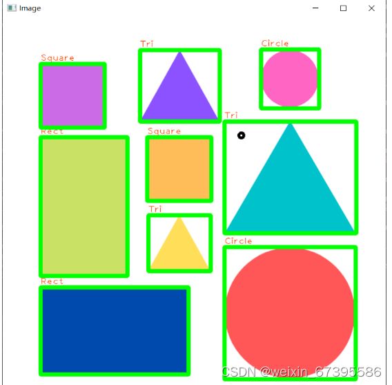
添加标注,需要对形状进行正确判断,才能添加标注。以根据 approxCurve 的顶点个数判断形状,例如三角形是三个顶点,矩形是四个顶点。
#include
#include
#include
#include
using namespace std;
using namespace cv;

void getContours(Mat imgDil, Mat img) {
    //imgDil是传入的扩张边缘的图像用来查找轮廓,img是要在其上绘制轮廓的图像
    vector> contours;//轮廓检测到的轮廓。每个轮廓线存储为一个点的向量

    //包含关于映像拓扑的信息  typedef Vec Vec4i;具有4个整数值
    vector hierarchy;
    //在二值图像中查找轮廓。该函数利用该算法从二值图像中提取轮廓
    findContours(imgDil, contours, hierarchy, RETR_EXTERNAL, CHAIN_APPROX_SIMPLE);
    vector> conPoly(contours.size());//定义approxCurve
    vector boundRect(contours.size());//定义存储边界框的变量
    for (int i = 0; i < contours.size(); i++) {//遍历检测到的轮廓
        int area = contourArea(contours[i]);
        //cout << area << endl;
        string objectType;//定义轮廓类型,便于添加文字到边界框
        if (area > 1000) {//轮廓面积>1000才绘制
            //定义 0.02*轮廓周长为给定的界限(精度)
            float peri = arcLength(contours[i], true);
            //以指定的精度近似多边形曲线。第二个参数conPloy[i]存储近似的结果,是输出。
            approxPolyDP(contours[i], conPoly[i], 0.02 * peri, true);
            boundRect[i] = boundingRect(conPoly[i]);//计算边界矩形
            //找近似多边形的角点,三角形有3个角点,矩形/正方形有4个角点,圆形>4个角点
            int objCor = (int)conPoly[i].size();
            //cout << objCor << endl;
            if (objCor == 3) { objectType = "Tri"; }
            else if (objCor == 4) {//四个角点进一步判断是正方形还是长方形
                float aspRatio = (float)boundRect[i].width / (float)boundRect[i].height;//宽高比
                if (aspRatio > 0.95 && aspRatio < 1.05) { objectType = "Square"; }
                else objectType = "Rect";
            }
            else if (objCor > 4) { objectType = "Circle"; }
            //drawContours(img, conPoly, i, Scalar(255, 0, 255), 2);
            //绘制边界矩形
            rectangle(img, boundRect[i].tl(), boundRect[i].br(), Scalar(0, 255, 0), 5);
            //添加标注,boundRect[i].y-5 是为了将文字房子框的上方
            putText(img, objectType, { boundRect[i].x,boundRect[i].y - 5 }/*文字坐标*/, FONT_HERSHEY_PLAIN, 1, Scalar(0, 69, 255), 1);
        }
    }
}

void main() {
    string path = "Resources/shapes.png";
    Mat img = imread(path);
    Mat imgGray, imgBlur, imgCanny, imgDil;
    cvtColor(img, imgGray, COLOR_BGR2GRAY);
    //cvt是convert的缩写,将图像从一种颜色空间转换为另一种颜色空间。
    GaussianBlur(imgGray, imgBlur, Size(3, 3), 3, 0);
    //使用高斯滤波器模糊图像。该函数将源图像与指定的高斯核进行卷积,Size(7,7)是核大小,数字越大越模糊
    Canny(imgBlur, imgCanny, 25, 75);
    //边缘检测,阈值1,2可调,目的:显示更多的边缘
    Mat kernel = getStructuringElement(MORPH_RECT, Size(3, 3));
    //创建一个核,增加Size(只能是奇数)会扩张/侵蚀更多
    dilate(imgCanny, imgDil, kernel);//扩张边缘(增加边缘厚度

    getContours(imgDil, img);//img是在其上绘轮廓的图片

    imshow("Image", img);
    waitKey(0);//增加延时,0表示无穷
}
运行上面程序,可以得到如下效果:


