仿真环境中生成专家轨迹
仿真环境中生成专家轨迹
文章目录
- 仿真环境中生成专家轨迹
-
- 简介
- 代码运行
- 步骤
-
- 获取输入数据
-
- Reference Trajectory
- Environment Pointcloud
- Full Quadrotor State
- 方法描述
- 输出规划轨迹
简介
本文为博客的子文,目的是生成专家轨迹,后续作为训练网络的真值标签,进行有监督学习。
仿真环境的整体运行流程如下:
- 全局规划
- 平滑轨迹
- kExecuteExpert模式下,选择专家轨迹中的最优轨迹。
- 然后控制飞机按照专家轨迹进行飞行,保存odometry.csv
- 然后对专家轨迹进行标签,得到轨迹真值label。
- 然后运行网络,并有标签真值轨迹进行有监督训练。
- 网络输出3条轨迹,kNetwork模式下,选择3条轨迹中的最优轨迹。
- 根据最优网络输出轨迹控制无人机运动,得到实际飞机的执行轨迹。
本模块主要实现全局规划,即专家轨迹的生成。流程框图如下:
 输入:
输入:
- Reference Trajectory
- Full Quadrotor State
- Environment Pointcloud
输出: 规划的前3条轨迹
方法:M-H采样
代码运行
参考Readme.md中《Collect your own dataset》的步骤,注意打开配置文件 default.yaml and label_generation.yaml.中的perform_global_planning选项。
步骤
获取输入数据
Reference Trajectory
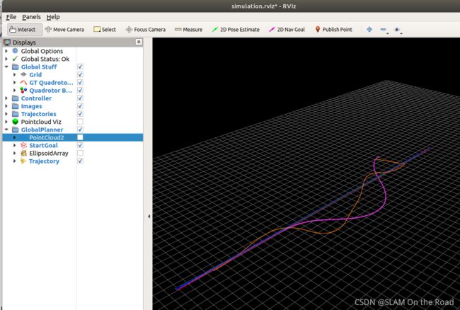
Reference Trajectory 通过给定起点和终点得到,是一条直线轨迹。
 上图中,直线为Reference Trajectory, 枚红色轨迹为全局规划的输出轨迹。橙色为深度学习网络训练生成的用于飞机的实际执行轨迹。
Environment Pointcloud
Environment Pointcloud 通过给定飞机的起点和终点(终点通过起点加上40m得到),可以获取unity场景的有限范围的真实点云。

Full Quadrotor State
仿真环境中使用状态估计器(state_predictor_)给出飞机的实时位姿。
状态估计器(state_predictor_)的主要估计位姿的方法是通过上一次的控制指令,以及现在的时间,进行积分,代码如下:
/// state_predictor.cpp
QuadExtStateEstimate StatePredictor::predictWithoutCommand(
    const QuadExtStateEstimate& old_state,
    const double total_integration_time) const
{
  QuadExtStateEstimate new_state = old_state;
  double current_integration_step = 0.0;
  double integrated_time = 0.0;

  while (integrated_time < total_integration_time)
  {
    current_integration_step = std::min(
        integration_step_size_, total_integration_time - integrated_time);
    new_state = dynamics(new_state, current_integration_step);
    integrated_time += current_integration_step;
  }

  return new_state;
}

QuadExtStateEstimate StatePredictor::dynamics(
    const QuadExtStateEstimate& old_state, const double dt) const
{
  QuadExtStateEstimate new_state;

  new_state.timestamp = old_state.timestamp + ros::Duration(dt);
  new_state.coordinate_frame = old_state.coordinate_frame;
  new_state.position = old_state.position + old_state.velocity * dt;
  new_state.velocity = old_state.velocity;
  new_state.orientation = quadrotor_common::integrateQuaternion(
      old_state.orientation, old_state.bodyrates, dt);
  new_state.bodyrates = old_state.bodyrates;
  new_state.thrust = old_state.thrust;

  return new_state;
}
而控制指令通过MPC控制器得到,MPC控制器需要给定预计的飞机位姿(predicted_state),待执行的轨迹(reference_trajectory),即可输出控制指令(control_cmd)。对应代码:
 control_cmd = base_controller_.run(predicted_state, reference_trajectory,
                                       base_controller_params_);
飞机的初始状态为悬停,位置为给定的飞机起点。此时,MPC控制器通过待执行的轨迹,和飞机的初始姿进行初始化估计(Solving MPC with hover as initial guess.),输出控制指令;–>有了初始控制指令+下一次的时间,可以用状态估计器(state_predictor_)来预测目的位姿。–> 然后有了预测的位姿,和待执行的轨迹,又可以MPC计算控制指令。以此往复,即可控制飞机跟随轨迹运动,并输出实时的飞机位姿。
方法描述
通过启动文件,可以看到全局规划通过ellipsoid_planner_node实现。
    <!-- Global Planning -->
    <include file="$(find mpl_test_node)/launch/ellipsoid_planner_node/global_planning.launch"/>
ellipsoid_planner_node流程 : 加载reference_trajectory.csv–>加载unity点云,转换为ros格式的点云,发布出去。–> 初始化planner (MPL::EllipsoidPlanner) ,并设置相应配置项–> 发布规划的起点和终点坐标 --> 运行轨迹规划(planner_->plan(start, goal);) --> 规划成功后,发布规划的轨迹,并保存ellipsoid_trajectory.csv。
planner 代码里面有两种规划算法: LPAstar 和 Astar。详细算法实现可以参考:S. Liu, K. Mohta, N. Atanasov, and V. Kumar, “Search-based motion planning for aggressive flight in se (3),” IEEE Robotics and Automation Letters, vol. 3, no. 3, pp. 2439–2446, 2018.
输出规划轨迹
全局规划轨迹完成之后,会有两个模块使用该轨迹。
(1) AgileAutonomy::completedGlobalPlanCallback 会进行如下处理:
- 加载生成的全局规划轨迹 ellipsoid_trajectory.csv
- 平滑轨迹,再保存
(2) GenerateLabel::generateInitialGuesses 会进行如下处理:
- 加载参考轨迹 ellipsoid_trajectory.csv
- 加载odometry.csv文件,该文件存放飞机的位姿。
- 根据每行的位姿获取对应的参考轨迹段 horizon_reference。并存为trajectory_ref_wf_*.csv。
- 将参考轨迹段和飞机的姿态,采用基于优化的MPC方法进行优化,得到优化过的轨迹段 optimized_reference。并保存为trajectory_mpc_opt_wf_*.csv。