基于Matlab的激光雷达、摄像头联合标定
基于Matlab的激光雷达、摄像头联合标定
一开始使用的是带白边的标定板进行标定,怎么都得不出结果,后来换成没有白边的小一点的板子才标定成功,此处要特别感谢高师姐和csdn的mychaoles博主和另一位一位网友!注意标定板 一定不要有白边! 一定不要有白边!
一定不要有白边!
在制作校园数据集时,需要将激光雷达点云投影到相机坐标系,故需要标定激光雷达到摄像头的外参矩阵,本次使用Matlab2020b中的软件进行联合标定,具体细节如下。
- 硬件信息
- 激光雷达:velodyne VLP 16
- 摄像头:Sony IMX 291
- 标定板:长700mm,宽630mm,每个方格边长70mm
1. 采集图像和点云数据
具体采集录制bag可以参见博客采集数据,这里提供另一种可以保存图像和点云数据的方法,解决了直接从bag包中提取点云和图像不是实时对应的问题,运行时:
- 在终端输入 i 即可刷新显示的点云
- 在终端输入 o 即可刷新显示的点云
- 在终端输入 e 退出提取程序
提取的图片和点云如下:


值得注意的是:
- 激光扫在标定板上的线束至少要有7条
- 标定板不同姿态、距离的多采集些
具体代码实现如下:
# 下载代码
cd catkin_ws/src
git clone https://github.com/young147/capture_pcd_img.git
cd ..
catkin_make
rosrun capture_pcd_img capture_node
- capture_pcd_img.cpp
#include 2. 标定相机内参
打开matlab里的Camera Calibrator,选择Add Images–>From File,将保存的图片导入,设置标定板方格大小70mm,点击calibrate,然后 Export Camera Parameters到工作区间,将生成的相机内参矩阵的cameraParams.mat数据另存为图片路径下calibration.mat。


3. 联合标定激光雷达和摄像头
筛选合适角度的图像和点云图后,用Matlab官网给出的例程,修改标定板方格大小为70mm,运行代码。
- lidar_cam_calibration.m
clc;clear all;close all;
imagePath = 'C:\Users\Young\Desktop\Matlab_ws\calib_data\image';
ptCloudPath = 'C:\Users\Young\Desktop\Matlab_ws\calib_data\pointcloud';
cameraParamsPath = fullfile(imagePath, 'calibration.mat');
intrinsic = load(cameraParamsPath); % Load camera intrinsics
imds = imageDatastore(imagePath); % Load images using imageDatastore
pcds = fileDatastore(ptCloudPath, 'ReadFcn', @pcread); % Load point cloud files
imageFileNames = imds.Files;
ptCloudFileNames = pcds.Files;
squareSize = 70; % Square size of the checkerboard
% Set random seed to generate reproducible results.
rng('default');
[imageCorners3d, checkerboardDimension, dataUsed] = ...
estimateCheckerboardCorners3d(imageFileNames, intrinsic.cameraParams, squareSize);
imageFileNames = imageFileNames(dataUsed); % Remove image files that are not used
% Display Checkerboard corners
% helperShowImageCorners(imageCorners3d, imageFileNames, intrinsic.cameraParams);
% Extract ROI from the detected image corners
roi = helperComputeROI(imageCorners3d, 5)
% Filter point cloud files corresponding to the detected images
ptCloudFileNames = ptCloudFileNames(dataUsed);
[lidarCheckerboardPlanes, framesUsed, indices] = ...
detectRectangularPlanePoints(ptCloudFileNames, checkerboardDimension, 'ROI', roi);
% Remove ptCloud files that are not used
ptCloudFileNames = ptCloudFileNames(framesUsed);
% Remove image files
imageFileNames = imageFileNames(framesUsed);
% Remove 3D corners from images
imageCorners3d = imageCorners3d(:, :, framesUsed);
% helperShowLidarCorners(ptCloudFileNames, indices);
[tform, errors] = estimateLidarCameraTransform(lidarCheckerboardPlanes, ...
imageCorners3d, 'CameraIntrinsic', intrinsic.cameraParams);
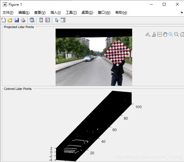
% visualize the lidar and the image data fused together
helperFuseLidarCamera(imageFileNames, ptCloudFileNames, indices, ...
intrinsic.cameraParams, tform);
% visualize the Errors
% The Errors include the follow:
% 1. Translation Error:Mean of difference between centroid of checkerboard
% corners in the lidar and the projected corners in 3D from an image.
% 2. Rotation Error: Mean of difference between the normals of checkerboard in the point cloud and the projected corners in 3-D from an image.
% 3. Reprojection Error:Mean of difference between the centroid of image
% corners and projected lidar corners on the image.
helperShowError(errors)
% Results
% After calibration check for data with high calibration errors and re-run the calibration.
outlierIdx = errors.RotationError < mean(errors.RotationError);
[newTform, newErrors] = estimateLidarCameraTransform(lidarCheckerboardPlanes(outlierIdx), ...
imageCorners3d(:, :, outlierIdx), 'CameraIntrinsic', intrinsic.cameraParams);
helperShowError(newErrors);
% Save the result
% dlmwrite('calib_result.txt',newTform.T)
Notes:
- 运行代码中报错: ‘helperShowImageCorners’ 用于 Lidar and Camera Calibration。 出错 test_calibration (第 23 行) helperShowImageCorners(imageCorners3d, imageFileNames, intrinsic.cameraParams);
则将下述几个代码拷贝在工作空间下。

- 上述.m文件可以通过以下链接下载:
链接:https://pan.baidu.com/s/1f5LJPMQXHPGwFP_L958g4Q
提取码:jklm
- 相机标定得出的内参矩阵和联合标定得出的转换矩阵都需要转置后才能使用。
- 联合标定结果