Rocket-chip学习基础篇
目录
1.Chipyard Basics 环境构建(done)
2.Chipyard Simulation 仿真
3.Chipyard included RTL Generator 一些生成器组件
4.Chipyard Development Tools
5.VLSI Flow
6.Customization
10. Prototyping Flow
chipyard document 6.9 教程
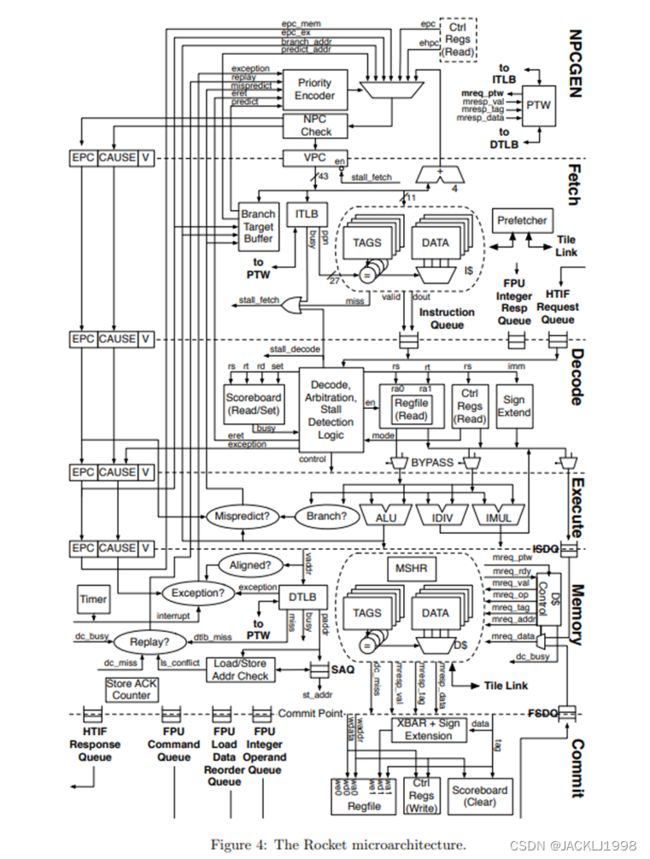
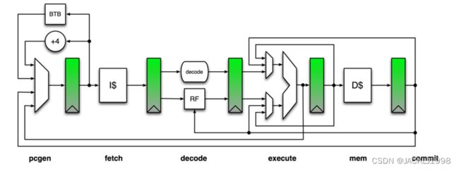
2.1 Rocket Pipeline
3.1 基本Config top to buttom
3.2 各级cache大小参数及具体实现代码
3.2.1 各级cache大小参数
3.2.2 cache具体实现代码
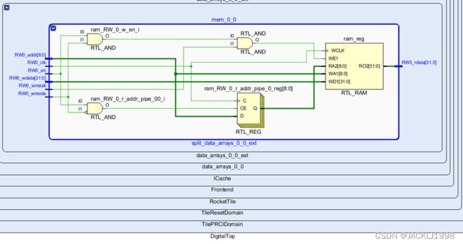
3.2.3 utilization
4.1 VCU118: Is it possible to use a pre-built Linux Image?
5.1 在zynq上跑rocket chip
5.1.1 RISCV开发流程
5.1.2 generate Verilog source
5.2 在Xilinx Virtex-7 VC707上跑Rocket chip
5.2.1 generate Verilog source
5.3 on Nexys4ddr 上跑Rocket chip
5.3.1 How a Linux gets booted
5.3.2 工程下的文件
5.3.3 generate Verilog source
5.4 freedom/FPGA shell 学习配置
5.4.1 generate Verilog source
5.5 FPGA Development using the Chipyard SoC Design Framework PDF
5.5.1 chipyard/fpga文件夹
5.5.2 USB-JTAG 和 Debugger
5.5.3 fpga/src/main/scala文件夹
5.6 FPGA-Shell custom
5.7 my system
5.7.1 make install Verilog
- Chipyard学习记录
- Chipyard document
1.Chipyard Basics 环境构建(done)
- riscv-tools and esp-tools
- source ./env.sh
1.1 riscv toolchain工具链
centos7虚拟机中直接指向
# auto-generated by build-toolchains.sh
export CHIPYARD_TOOLCHAIN_SOURCED=1
export RISCV=/home/ICer/chipyard_prj/chipyard/riscv-tools-install
export PATH=${RISCV}/bin:${PATH}
export LD_LIBRARY_PATH=${RISCV}/lib${LD_LIBRARY_PATH:+":${LD_LIBRARY_PATH}"}
1.2 Configs, Parameters, Mixins, and Everything In Between
2.Chipyard Simulation 仿真
- make CONFIG=RocketConfig -j16 会elaborate the RocketConfig,然后产生一个可执行文件simulator-chipyard-RocketConfig。
这个可执行文件是一个simulator,它是根据构建的设计编译的。然后可以使用此可执行文件运行任何兼容的RV64代码。例如,运行一个riscv工具组件测试。./simulator-chipyard-RocketConfig $RISCV/riscv64-unknown-elf/share/riscv-tests/isa/rv64ui-p-simple
- Makefile有run-binary rule可以简化跑仿真可执行文件,加了很多常用命令行选项且把输出重定向到文件。
make run-binary BINARY=$RISCV/riscv64-unknown-elf/share/riscv-tests/isa/rv64ui-p-simple
- 也可以跑一个先前打包好的RISCV assembly或者benchmark tests。
make run-asm-tests
make run-bmark-tests
- some Makefile variables
3.Chipyard included RTL Generator 一些生成器组件
Ⅰ.Rocket Chip
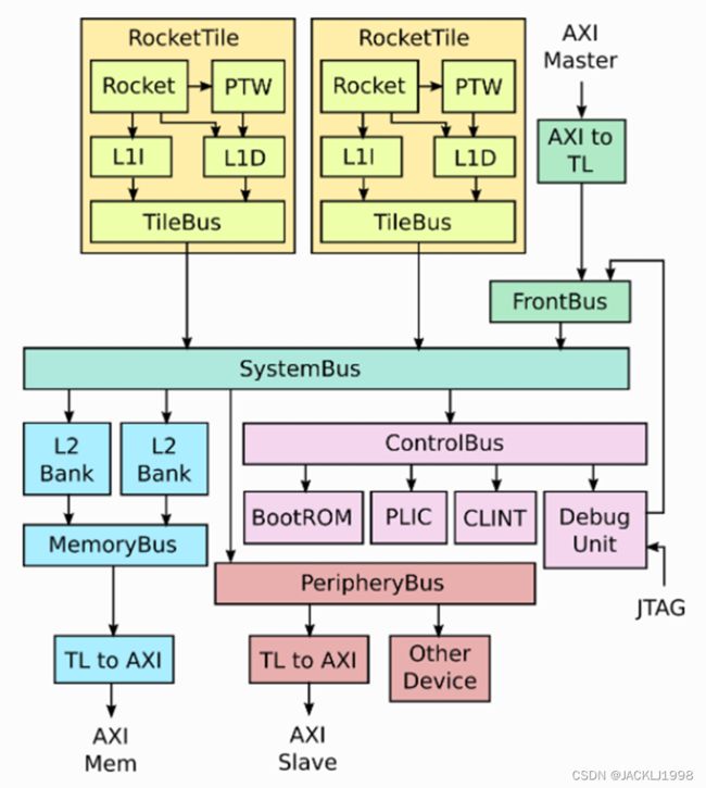
- PTW:page table walker 一个MMU内存管理单元只要分为两个部分,一个PTW和一个内容可寻址内存(称为translation lookaside buffer, TLB页表缓存)用来加速地址翻译查找。
4.3 页表(Page Table) - 知乎 (zhihu.com)
MMU原理 - 知乎 (zhihu.com)
Architectural and OS support for Virtual Memory - 知乎 (zhihu.com)
Ⅱ.Rocket Core
- 五级流水线有序标量处理器核生成器。
- 支持开源RV64GC指令集
- 有一个支持基于page的虚拟内存的MMU,一个非阻塞data cache,一个带有分支预测的front-end前端。
- 配备浮点运算单元FPU。
- 支持RISC-V机器machine,特权supervisor和用户user三种权限级别。
- exposed许多参数,包括一些ISA扩展(M、A、F、D)的可选支持、浮点流水级数的数量以及缓存和TLB大小。
Ⅲ.BOOM Core
Ⅳ.Hwacha
- Hwacha项目正在为功率和能耗受限的未来计算机系统开发一种新的矢量体系结构。
- Hwacha项目包括Hwacha微架构生成器以及XHwacha非标准RISC-V扩展。Hwacha未实施RISC-V标准向量扩展提案。
Ⅴ.Gemmini
https://github.com/ucb-bar/gemmini/blob/master/README.md
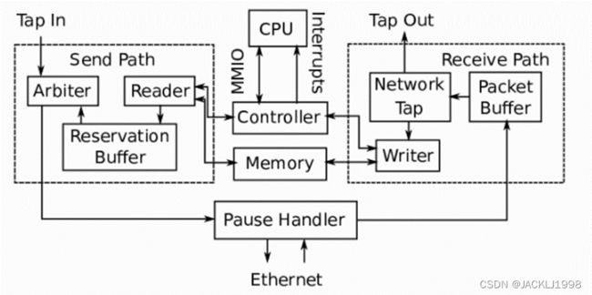
Ⅵ.IceNet
Ⅶ.Test Chip IP
Chipyard包括一个测试芯片IP库,该库提供了在设计SOC时可能有用的各种硬件小部件。包括Serial Adapter, Block Device Controller, TileLink SERDES, TileLink Switcher, TileLink Ring Network, and UART Adapter, SPI Flash Model。
Ⅷ.SiFive Generator
- Last-Level Cache Generator used to be L2cache
- sifive-blocks includes multiple peripheral device generators, such as UART, SPI, PWM, JTAG, GPIO and more.
Ⅸ.SHA3 ROCC Accelerator
- SHA3加速器是SHA3哈希算法的基本RoCC加速器。它是一个将自定义加速器集成到Chipyard中的独立、简单的示例。
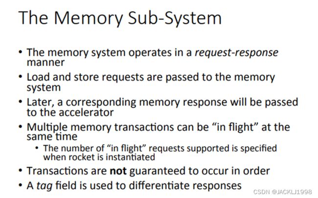
- RoCC accelerator 通常围绕三个sub-systems设计,an interface with the processor, an interface with memory, the actual computation system
Ⅹ.NVDLA
(17条消息) AI芯片:英伟达NVDLA结构分析_evolone的专栏-CSDN博客_nvdla
(17条消息) NVDLA学习笔记(1)_夏风喃喃的博客-CSDN博客_nvdla
神经网络加速器NVDLA顶层接口与工作流程 - 知乎 (zhihu.com)
4.Chipyard Development Tools
Ⅰ.Chisel
Ⅱ.FIRRTL
Ⅲ. Treadle and FIRRTL Interpreter
Ⅳ. Chisel Testers
Ⅴ. Dsptools
Ⅵ. Barstools
Ⅶ. Dromajo
5.VLSI Flow
Ⅰ.
Ⅱ.
Ⅲ.
Ⅳ.
Ⅴ.
Ⅵ.
Ⅶ.
Ⅷ.
6.Customization
Ⅰ.Heterogeneous SoCs
Ⅱ. Integrating Custom Chisel Projects into the Generator Build System
Ⅲ. Adding a custom core
Ⅳ. RoCC vs MMIO
加速器Accelerator和定制IO设备可以通过以下两种方法加到SoC中:
- MMIO Peripheral (a.k.a TileLink-Attached Accelerator)
- Tightly-Coupled RoCC Accelerator
以上两种方式在core/processor与定制block之间的通信方式上存在区别
MMIO设备通过 存储器映射寄存器 与core通信。
RoCC设备 通过定制协议和定制的非标准ISA指令与core通信。每个core最多有4个accelerators被定制的指令控制且可以与CPU分享resource。
Ⅴ. Adding a RoCC Accelerator
Ⅵ. MMIO Peripherals
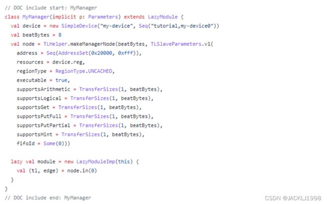
- 最简单的构造MMIO外设的方法:使用TLRegisterRouter 或者 AXI4RegisterRouter 组件,它们俩将 处理互连协议interconnect protocols的细节抽象出来,并为指定内存映射寄存器提供方便的接口。
- 创建一个基于RegisterRoute的外设,需要 1.为配置设置指定一个参数 case class xxx-parameter 2.具有额外增加外部顶级接口的trait 3.具体RTL的module实现
Ⅶ. Dsptools Blocks
Ⅷ.. Keys, Traits, and Configs
Ⅸ. Adding a DMA Device
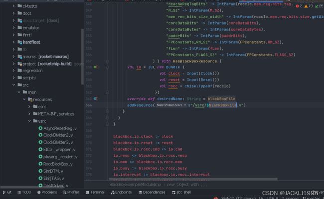
Ⅹ. Incorporating Verilog Blocks
ⅩⅠ. Memory Hierarchy
6.11. Memory Hierarchy — Chipyard main documentation
chipyard存储架构部分:
- 可以看到存储架构中每个CPU core 都有一个私人L1 dcache/L1 icache
默认The default RocketConfig uses 16 KiB, 4-way set-associative instruction and data caches.
- L1 cache可以配置 cache容量大小 以及 the number of lines
- use rocket L1 DCache scratchpad as base phys mem:L1 dcache 也可以被配置成scratchpad,但是如果使用data scratchpad,只能使用a single core,也不能添加外部DRAM设计,且这样配置去除了L2cache和mbus等配置。
- SiFive L2 Cache
- 默认config用了SiFive的 InclusiveCache generator 产生L2cache single cache bank with 512 KiB capacity and 8-way set-associativity。lines/ways和bank的数量在配置时必须是2的指数。
- 如果不想使用L2 cache(例如,对于资源有限的嵌入式设计),可以创建不使用二级缓存的配置。使用RocketChip的TileLink broadcast hub(block-inclusivecache-sifive/Configs.scala at master · sifive/block-inclusivecache-sifive (github.com))。要进行这样的配置,只需复制RocketConfig的定义,但从包含的Mixim列表中省略WithInclusiveCache config。
如果您想进一步减少使用的资源,可以将TileLink broadcast hub配置为使用a bufferless design。freechips.rocketchip.subsystem.WithBufferlessBroadcastHub
- 外部储存系统
- The L2 coherence agent (either L2 cache or Broadcast Hub) 向 包含了兼容AXI4总线接口的DRAM控制器 的外部内存系统发出请求。
- 默认配置使用a single memory channel,可以将系统配置为使用多个通道。与L2 cache banks的数量一样,DRAM channel numbers限制为2的指数。
- In VCS and Verilator simulation,DRAM使用SimAXIMem Module进行模拟,该模块仅将a single-cycle SRAM连接到每个memory channel。
外部存储除了连接off-chip DRAM外,可以连接scratchpad并移除off-chip link。
- 可以用firesim仿真ddr controllers 的时序
ⅩⅡ. Chipyard Boot Process
12.1 bootrom
- bootrom作为一个MMIO TileLink接口的外设连接在controlbus上。
- bootROM包含第一级bootloader,即系统完成复位后运行的第一条指令。它还包含Device Tree,Linux使用 Device Tree来确定连接了哪些其他外设。
- 基于chipyard SoC boot a linux:
1. BootROM包含SoC通电时运行的第一条指令以及 详细说明系统组件的Device Tree Binary(dtb)
2. BootROM代码的程序集位于generators/testchipip/src/main/resources/testchipip/BootROM/BootROM.S 中
3. BootROM address 从0x10000开始(BootROMParams中指定),程序执行从reset vector复位向量0x10040开始(由BootROMParams中的linker script 和 reset vector给出),该地址0x10040由BootROM 汇编中的_hang标签标记
4. The Chisel generator在elaboration的时候将汇编好的指令 编码到 BootROM硬件中。因此如果要更改BootROM代码,则需要在BootROM目录下运行make,然后重新生成Verilog。 如果不想覆盖现有的bootrom.S,还可以通过修改配置中的BootROMParams Key,将生成器指向不同的bootrom image 。
12.2 bootloader
- 当RISC-V frontend-server(FESVR)加载actual program时,默认bootloader只是在wait-for-interrupt (WFI)指令上循环。
FESVR是一个在host CPU上运行的程序,可以使用Tethered Serial Interface (TSI)读取/写入目标系统存储的任意部分。
- FESVR 使用 TSI 将baremetal executable 或者 second-stage bootloader加载到 SoC memory中。在Software RTL Simulation 中,这是仿真运行的二进制文件。一旦完成load executable,FESVR 将对 CPU 0 的software interrupt register写入,CPU 0 退出WFI 循环。一旦接收到中断,CPU 0 将对系统中其他 CPU 的software interrupt写入,然后跳转到 DRAM 的开头执行FESVR load的可执行文件的第一条指令。其他 CPU 将被CPU 0 唤醒,并跳转到 DRAM 的开头。对于baremetal program,加载的可执行文件将在机器模式下运行,直到它通过to host寄存器发送命令告诉 FESVR 关闭 SoC。
- FESVR加载的可执行文件应具有指定为tohost和fromhost的内存位置。FESVR在可执行文件运行后使用这些内存位置与可执行文件通信。
可执行文件使用tohost向FESVR发送命令,用于打印到控制台、代理系统调用和关闭SoC。
fromhost寄存器用于发回tohost命令的响应和发送控制台输入。
12.3 second-stage bootloader (Berkeley Boot Loader) BBL
- 要引导 Linux Kernel,需要 Berkeley Boot Loader( BBL) second-stage bootloader。该程序读取boot ROM 中编码的device tree,并将其转换为与 Linux kernel兼容的格式。然后它设置虚拟内存和中断控制器,加载kernel,kernel作为payload有效负载嵌入引导bootloader binary中,并开始在supervisor mode下执行kernel。bootloader还负责为kernel中的machine-mode trap提供服务,并通过 FESVR 代理它们。
- 一旦 BBL 跳转到supervisor mode,Linux kernel就会接管并开始其进程。它最终加载init程序并在user mode下运行它,从而启动用户空间执行。
ⅩⅢ. Adding a Firrtl Transform
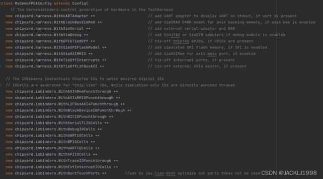
ⅩⅣ. IOBinders and HarnessBinders
chipyard中使用了parameter key, IOBinders and HarnessBinders来减小在数字系统IOs和TestHarness之间的gap.
- IOBinders 函数负责实例化ChipTop 中的IO cell和IOPort。
- HarnessBinder函数决定哪个module 要绑定 到TestHarness中ChipTop的IOs上。HarnessBinder接口设计为可在各种仿真/实现模式中重用,从而实现 目标设计 与 仿真和测试问题的解耦。
对于软件 RTL仿真或GL模拟,默认的HarnessBinder setv实例化各种外部device的软件仿真模型(例如external memory或UART),并将这些模型连接到ChipTop的IOs。
10. Prototyping Flow
10.1 General Setup and Usage
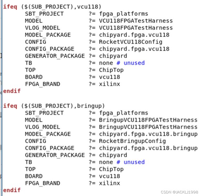
- 生成bitstream makefile命令参数
- SUB_PROJECT :相当于一个make原变量,设置该变量后可以默认设置其他相关变量
10.2
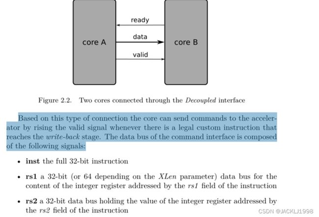
- The RoCC coprocessor interface
下面RoCC协处理器接口的主要细节,并使用read/write操作模型对core和accelerator之间的数据交换的延迟进行了分析。对协处理器和存储器之间的数据传输,引入了一种load/store指令模型。
第一节介绍了组成RoCC接口的主要信号组和sub-interfacts,重点介绍了与core和L1cache缓存的通信。第二部分介绍了指令的格式和使用。第三部分描述了评估core与co-processor之间数据传输的性能和开销的方法和延迟研究。最后一节给出了一个类似的分析,描述了memory-sub-interfact的使用和性能。
- RoCC interface overview(Rocket Custom Coprocessor Interface)=> (RoCC)
除了以下这四个channel之外,RoCC接口还提供了更多的sub-interfact,以实现高级功能,特别是可以将加速器与FPU连接;共享PTW(page table walker),并与外部存储系统直接连接起来。这些额外的子接口是所谓的Extended RoCC接口的一部分。
该接口还提供一些更多的state信号和interrupt 线路,可用于与syncronising with the core or for signalling errors。
Ⅰ.cmd和response接口
![]()
cmd channel用来core送指令和相应的数据给co-processor,response接口则用于将结果从co-processor发送到integer register file。
- 每个channel都用DecoupledIO
Ⅱ. mem_req(request) mem_resp(response)接口
为了让协处理器可以访问存储而定义的接口。
- Add a DMA to Chipyard
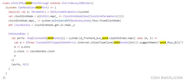
DMA做为Master可以发送存取命令给存储系统。可以直接通过TileLink总线FrontendBus连接也可以通过TLtoAXI然后连接一个AXI4-DMA。
chipyard document 6.9 教程
- 在chipyard/generators/chipyard/src/main/scala/example/InitZero.scala文件中生成了一个可以配置地址给存储器写0的DMA设备。
- 首先case class InitZeroConfig(base: BigInt, size: BigInt)提供了一个提供base基地址和size大小参数的case class
- 配置一个带AXI-fbus/cbus-AXI接口的简单chipyard SoC
- TLtoAXI/AXItoTL的IO bundles
- 在顶层Config文件中注释掉
v
会在生成的SoC system中生成带有mbus-axi4 sbus-axi4 axi4-fpus三个总线转换
- rocket-chip/src/main/scala/subsystem/Configs.scala
在以上文件中有Tile Parameters/Interconnect parameters/Additional device Parameters
- slave port / mmio port
withdefaultslaveport ------- AXI4toTL-frontbus
withdefaultmmioport ------- PeripheralBus-TLtoAXI4
- 挂载pbus-axi4-gcd外设 and pbus-axi4-adder外设并完成测试
https://github.com/ucb-bar/chipyard/issues/590
同样方法可以挂在pbus/cbus/mbus上
- 挂载dma-axi4-fbus 并完成测试
- gcd_busy端口不被优化/在digital top和chip top模块中
Top-level trait from GCD example not being generated · Issue #943 · ucb-bar/chipyard · GitHub
- WithSimAXIMMIO lost part of axi port-----WithDontTouchPorts ++
https://github.com/ucb-bar/chipyard/issues/628
- site up here 机制的介绍
Chisel初体验——高级参数化PART1: Site/Here/Up机制(五) - 知乎 (zhihu.com)
- diplomacy机制的学习
Chisel初体验——高级参数化PART2: Dipomacy机制(六) - 知乎 (zhihu.com)
- TileLink Client Node
9.1. TileLink Node Types — Chipyard documentation
- TLRegisterRouter 构造TileLink的连接
正在上传…重新上传取消
https://github.com/ucb-bar/chipyard/blob/e3d23f10345cfafd9a2f4f8aacfe07c2746699f9/docs/Customization/MMIO-Peripherals.rst
TLRegisterRouter的参数分为三组参数,第一组参数确定寄存器路由器将放置在全局地址映射中的位置,以及将在其设备树条目中放置哪些信息。第二组参数是IO bundle构造函数,我们通过使用bundle特性扩展TLRegBundle来创建它。最后一组参数是模块构造函数,我们使用模块特性扩展TLRegModule来创建它。请注意,我们如何创建类似于AXI4版本的外围设备。
- How to link a blackbox to memory node and cbus?
https://github.com/ucb-bar/chipyard/issues/760
- Here's what the AXI <-> TL conversion looks like for the NVDLA's DBB port
https://github.com/ucb-bar/chipyard/issues/573
- AXI4 Master Node
https://github.com/ucb-bar/chipyard/blob/e3d23f10345cfafd9a2f4f8aacfe07c2746699f9/generators/chipyard/src/main/scala/example/TutorialTile.scala
- TL Client Node/Node Types
chipyard/NodeTypes.scala at e3d23f10345cfafd9a2f4f8aacfe07c2746699f9 · ucb-bar/chipyard · GitHub
- MasterAXI4MMIOPort and SlaveAXI4Port TOP
https://github.com/ucb-bar/chipyard/pull/341
Remove MasterAXI4MMIOPort and SlaveAXI4Port by abejgonzalez · Pull Request #341 · ucb-bar/chipyard · GitHub
- Revamp the config system for Top/Harness
https://github.com/ucb-bar/chipyard/pull/347
- tilelink总线上的三种端口ports
![]()
顶层axi4 ports /mmio master ports / fbus slave ports
只要配置有memports 默认为AXI4端口:module TLInterconnectCoupler_15 为TL2AXI4
- Rocket Core具体学习
2.1 Rocket Pipeline
五级流水线基本结构:IF(PCGEN+Fetch) / ID / EX / MEM / WB
v
31个整数register file
2.1.1 IF stage
- 配置一个自定义的chipyard soc
3.1 基本Config top to buttom
- IOBinders 函数负责实例化ChipTop 中的IO cell和IOPort。
分为IOcells和Punchthrough ,有些ports只是仿真需要可以直接punchthrough到最外层chiptop。
- HarnessBinder函数决定哪个module 要绑定 到TestHarness中ChipTop的IOs上。HarnessBinder接口设计为可在各种仿真/实现模式中重用,从而实现 目标设计 与 仿真和测试问题的解耦。
可以通过AXI4-MEM ports 连接一个 外部Mem模块用于仿真
DigitTop可以选择配置以下外设
- 配置了TL ports可以连接到系统外部的serialadapter/harnessRAM
- 配置使用了L2 TLB ,UART ,默认的BOOTROM
- 系统从顶层ChipTop通过外接时钟驱动子系统,而不是使用隐式时钟
- 每个连接到总线上的device如果未设置频率会自动接收来自该总线的频率
- 如果有总线设置了总线频率,未设置时钟频率的其他总线继承与该总线相同的时钟频率。
- pbus上默认时钟频率为100MHZ
- 配置了系统没有外部中断,存在L2cache,rocket core,多时钟域互联总线,顶层axi4-mem端口,去掉了顶层axi4-slave和axi4-master ports
以下是L2cache的默认配置大小,可以配置L2cache的banks , ways , capacityKB , outerLatencyCycles , subBankingFactor
![]()
override config 在chiptop最外层只有Mem接口,config去掉了MMIO和Slave接口。
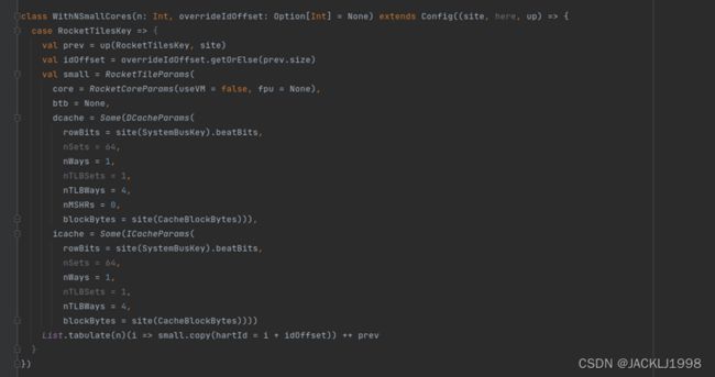
smallCore配置cache为4KiB直接映射cache
PgLevels:虚拟地址lookaside page页表的的levels,TLB
XLen:core的数据总线宽度
MaxHartIdBits:cores的数量,根据system配置自动确定
总线interconnect基本配置:
beatBytes总线宽度,一个时钟周期最大能请求的字节数
blockBytes:cache的linesize?
一些基本control bus上device的参数config
![]()
3.2 各级cache大小参数及具体实现代码
3.2.1 各级cache大小参数
- 默认L1 Dcache/Icache 配置为64个sets , 每个blocks有4 ways,blockBytes = 64,dcache默认配置容量64×4×64 = 16 KiB,四路组相联。
![]()
- 默认L2 cache的配置,大小为512KiB八路组相联
3.2.2 cache具体实现代码
- L1Dcache
- L1ICache
- L2 Cache
3.2.3 utilization
- chipyard issues
4.1 VCU118: Is it possible to use a pre-built Linux Image?
https://github.com/ucb-bar/chipyard/issues/957
- 在FPGA上跑Rocket Chip
5.1 在zynq上跑rocket chip
https://github.com/ucb-bar/fpga-zynq#overview
5.1.1 RISCV开发流程
1 Target Application (RISC-V binary)
will run on top of whatever kernel the rocket chip is running. Compiled by riscv-gcc or riscv-llvm.
https://github.com/riscv-collab/riscv-gcc
https://github.com/ucb-bar/esp-llvm
2 RISC-V Kernel (proxy kernel or RISC-V Linux)
runs on top of the rocket chip. The proxy kernel is extremely lightweight and designed to be used with a single binary linked against Newlib while RISC-V Linux is appropriate for everything else.
https://github.com/riscv-software-src/riscv-pk
3 Rocket Chip (rocket core with L1 instruction and data caches)
is instantiated on the FPGA. Many of its structures will typically map to various hard blocks including BRAMs and DSP slices. It communicates to the host ARM core on the Zynq via AXI.
4 Front-end Server (riscv-fesvr)
runs on the host ARM core and provides an interface to the rocket chip running on the FPGA (connected via AXI).
https://github.com/riscvarchive/riscv-fesvr
5 Zynq ARM Core (actually dual Cortex A9)
runs Linux and simplifies interfacing with the FPGA.
6 FPGA Board (Zybo, Zedboard, or ZC706)
contains the Zynq FPGA and several I/O devices. At power on, the contents of the SD card are used to configure the FPGA and boot Linux on the ARM core.
7 External Communication (TTY over serial on USB or telnet/ssh over ethernet)
allows the development system to communicate with the FPGA board.
8 Development System (PC with SD card reader)
generates the images to configure the FPGA.
5.1.2 generate Verilog source
make rocket
5.2 在Xilinx Virtex-7 VC707上跑Rocket chip
https://github.com/riscv-zju/riscv-starship
5.2.1 generate Verilog source
make bitstream :
生成verilog一般需要一个 StarshipFPGATop extends StarshipSystem extends RocketSubsystem 然后TestHarness 
在rocket-chip默认配置中:
- TestHarness (ldut = LazyModule(new ExampleRocketSystem))
- ExampleRocketSystem extends RocketSubsystem
然后需要config文件 ,在此项目中:
class StarshipBaseConfig extends Config ++ BaseConfig
class StarshipFPGAConfig extends Config ++ StarshipBaseConfig
顶层CONFIG和顶层MODEL需要指明。
5.3 on Nexys4ddr 上跑Rocket chip
https://github.com/cnrv/fpga-rocket-chip
5.3.1 How a Linux gets booted
- 上电后,PC(program counter) 根据可Reset_Vector被设为0x10040。执行ExampleRocketChip内部TLBootrom(@0x10000)的指令。TLBootrom包含要求处理器跳转到BRAM_64K(@0x60010000)的指令。
li s0, BRAM_BASE, jr s0 ( /rocket-chip/bootrom.S )
- 在BRAM_64K中,完成first stage bootloader (aka FSBL)的两个任务:将包含BBL(Berkeley bootloader)和 vmlinux image的elf图像复制到DDR中的某个地址(@0x870000000),并将这个elf提取到DDR的开头(@0x80000000)。在这两个任务之后,FSBL将跳转到DDR,PC将转到BBL程序。
li s0, DDR_BASE, jr s0 ( /firmware/head.S )
- 在DDR中,BBL会做一些准备工作,包括。setting traps, SBI (supervisor binary interface) and physical memory protection。然后把一个DTB(device tree blob)交给内核(在早期版本中,BBL还对内存进行了虚拟化,现在直接由Linux处理)。最终,BBL启动了Linux内核。
enter_supervisor_mode(entry, hartid, dtb_output()) ( /riscv-pk/bbl/bbl.c )
- 内核初始化后,busybox_init启动并调用busybox_ash,它为你提供了一个命令行界面。
5.3.2 工程下的文件
- constraints, verilog, firmware :这几个文件vivado项目的source file和FPGA constrain file。firmware文件夹里包含了SDloader程序(firmware.hex),它将一个elf image加载到DDR中,作为FSBL发挥作用。它将被烧入BRAM_64K。
- riscv-pk :riscv/riscv-pk repo的一个修改版本。BBL和Linux内核将被放入SD卡,并由FSBL加载到DDR。注意:我们把DTB植入到BBL中,并稍微改变了uart驱动。一般来说,DTB应该位于固件中,但是为了调试的方便(改变固件并将其重新烧入FPGA是很耗时的),我把它放在bbl里面。DTS位于riscv-pk/build。
- rocket-chip : freechipsproject/rocket-chip的官方repo。我们的makefile将自动把/rocket-chip/bootrom替换成/firmware/TLBootrom,这样CPU一上电就可以跳到BRAM_64K。
5.3.3 generate Verilog source
make vivado_source
- bootrom替换
- 生成verilog 。rocket-chip/vsim执行make Verilog
变量名 : MODEL顶层模块
CONFIG顶层配置
使用了默认变量生成configfreechips.rocketchip.system.DefaultConfig.v,需要其中ExampleRocketSystem模块。
5.4 freedom/FPGA shell 学习配置
https://github.com/Phantom1003/fpga-shells
5.4.1 generate Verilog source
make verilog
5.5 FPGA Development using the Chipyard SoC Design Framework PDF
5.5.1 chipyard/fpga文件夹
- harness binders连接到TestHarness上,而不是物理上的IOs。为了连接到物理IOs,需要IO binders.
5.5.2 USB-JTAG 和 Debugger
- 在FPGA板子的USB-JTAG port (J10)和host 主机上连接好USB Type A to Micro-B。这为Freedom E310 Arty FPGA Dev Kit提供了通用UART console access,并为电路板提供了5V电源。
- Debugger将代码下载和调试到SDK。编译后的软件可执行文件会下载到SPI Flash。没有Debuuger只能flash the FPGA image并运行image demo,不能改执行的软件代码。
5.5.3 fpga/src/main/scala文件夹
- Config.scala
- HarnessBinders.scala
- IOBinders.scala
- TestHarness.scala
5.6 FPGA-Shell custom
每个shell由Overlays组成,Overlays使用dependency injection来创建peripheral device interfaces,并将FPGADesign中的peripheral device interfaces连接到top-level shell模块。
大多数设备已经在 fpga-shell/src/main/scala/shell[/xilinx]中为它们定义了一个overlay。如果使用的是Xilinx设备,可能想使用Xilinx专用的overlay,因为它定义了一些你必须自己指定的东西。
一般需要创建一个扩展了Series7Shell或UltraScaleShell的device shell。如果你需要不同的功能(或者你不使用Xilinx设备),你可以扩展Shell并implement abstract members。
5.7 my system
5.7.1 make install Verilog
- RISCV工具链
riscv-software-src/riscv-tools: RISC-V Tools (ISA Simulator and Tests) (github.com)
D:\桌面\2021学习记录\chipyard项目\riscv-software-toolchain-workshop-jan2015.pdf
- riscv-isa-sim的使用
riscv-software-src/riscv-isa-sim: Spike, a RISC-V ISA Simulator (github.com)
Spike, the RISC-V ISA Simulator。实现了一个或多个RISC-V harts的功能模型。riscv-isa-sim是一个RISC-V指令的仿真器,riscv-isa-sim的正常运行需要依赖riscv-pk和riscv-fesvr工具。
新的指令仿真
(12条消息) riscv-isa-sim的使用_a_weiming的博客-CSDN博客_riscv-isa-sim
(12条消息) Rocket之加速器_qihao-CSDN博客_rocket加速器
- RISCV编译和汇编环境
(12条消息) 如何建立自己的RISC-V编译环境--汇编?_a_weiming的博客-CSDN博客_riscv32 汇编
(12条消息) 如何建立自己的RISC-V编译环境--C_Code?_a_weiming的博客-CSDN博客_risc-v编译器
- rocket-chip FPGA验证
- 配置makefile生成mcs文件综合编译过后的.bin二进制文件和.bit文件
修改默认common.mk文件中 mcs文件生成的方式
![]()
在Makefile中,将FLASHED_PROGRAM设置为.bin文件路径。freedom-e-sdk生成的程序是.ihex格式。
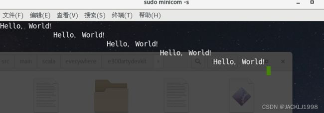
riscv64-unknown-elf-objcopy -O binary ~/freedom-e-sdk/software/hello/debug/hello.elf ~/freedom-e-sdk/software/hello/debug/hello.bin
- 实际生成mcs文件的脚本fpga-shell中的write_cfgmem.tcl
- FPGA验证 rocket-core基础配置
- bootrom 修改
(6条消息) Rocket-Chip-Rom_a_weiming的博客-CSDN博客
- 添加rocc协处理器进行测试
- custom一个简单的ROCC
- LazyRoCC.scala文件:
- 上板验证,通过SDK调试编译好的文件
- 挂载一个TLSRAM
- 为32bits core编译生成.riscv executable文件
- Tiny config core scratchpad is too small to benchmarks
Tiny Config benchmark problem · Issue #1011 · chipsalliance/rocket-chip (github.com)
- How to use riscv64-unknown-elf-gcc to compile rv32
All Aboard, Part 1: The -march, -mabi, and -mtune arguments to RISC-V Compilers - SiFive
Failed to compile c program in tests directory with 32bit configuration · Issue #23 · ucb-bar/chipyard (github.com)
All Aboard, Part 1: The -march, -mabi, and -mtune arguments to RISC-V Compilers - SiFive
- 32rv 或者 64rv core regmap问题
Is it possible to use a 32bit address peripheral with a 64-bit core? · Issue #987 · ucb-bar/chipyard (github.com)
- Riscv toolchain gcc
RISC-V GNU工具链的编译与安装 - 知乎 (zhihu.com)
学习第一步:RISC-V GCC工具链编译安装~_riscv
编译了riscv32 和 riscv64两个版本的工具链,可以根据chipyard/scripts/build-toolchains.sh里面的具体步骤看riscv32和riscv64的编译过程区别。 好像可以直接编译cross compile同时支持两者,暂时没有试。
Chipyard/tests/Makefile 里面修改编译器riscv32 or riscv64
- Rocket chip vsim 仿真tinyconfig
需要修改DTIM大小,default scratchpad 太小导致仿真出问题。
Tiny Config benchmark problem · Issue #1011 · chipsalliance/rocket-chip (github.com)
修改后暂时helloworld.riscv仿真没问题。
???但是为什么将tiny core改为RV64不会需要修改DTIM大小,可以直接跑完仿真?
- Rocket ChipDMA 设计记录
- Block diagram:
- Bandwidth utilization: 2 cycle per word, data width (<50% utilization)
这个问题是因为我之前测的是DMA内存DMEM的原因,DMEM在rocket chip里面是直接写了一个scratchpad dram,仿真的时候不是single-cycle的, 然后我换成读写single-cycle SRAM的话,DMA几乎能跑满bandwidth, 每次读写是1cycle。
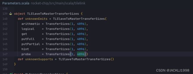
- larger packet: 32 --> 4096
TileLink: Increase max burst size · Issue #1618 · chipsalliance/rocket-chip (github.com)
暂时SRAM没有burst, DMEM burst size 最大只能64Bytes .
- maxbytes = 32 ----- DMEM burst size = 5
- maxbytes >=64 ----- DMEM burst size = 6 ,why?
怎么修改rocket chip的burst size大小
Rocket - tilelink - Fragmenter - wjcdx - 博客园 (cnblogs.com)
- SRAM实现的busProtocol 协议等级 从TL-UL à TL-UH支持burst
通过 TLFragmenter
实现burst大小调整:
Burst size : 2^8 Bytes = 256Bytes
Burst size : 2^10 Bytes = 1024Bytes
Max Burst size : 2^12 Bytes = 4096Bytes
default max burst size=4096B , 可以调整参数继续调大burst size?
![]()
- Parameter 参数化,实现DMA参数化
现在例化一个DMA需要两个参数 ,address是DMA control的regmap基地址,以及DMA beatBytes等于总线data beatBytes宽度。
- Regmap 寄存器设计细节
The DMA device can act as a bus master and can read and write physical memory. 理论上DMA应该支持contiguous transfer and scatter-gather lists两种模式。先设计contiguous transfer mode,但是为scatter-gather lists mode预留了config regmap bits。
- i. Rocket Chip address bits length = 32
Rocket chip目前a channel address bit length = 32bits,因为max physical address is 80040000
- ii. Regmap Register Documentation
目前设计DMA 有三个control regmap寄存器如下表
base address:0x10016000, size 0x1000 bits
| Offset |
Register(32bits) |
Documentation |
| 0x00 |
DMA control |
Control register |
| 0x04 |
DMA source |
Source Address |
| 0x08 |
DMA destination |
Destination Address |
- 首先介绍DMA Control Register的构成
| EN[31] |
DMA 使能位 |
| SWT[30] |
Software Transfer Trigger |
| ECI[29] |
Enable Completion Interrupt |
| TC[28] |
Transfer Complete. |
| SG[27] |
Scatter-Gather List Input. |
| ERR[26] |
DMA Transfer Error. |
| TS[15:0] |
Transfer Size. |
- DMA暂时问题
由于TL总线只有a和d两个channel,所以暂时不能做到pipeline read+write操作,先研究TL-AXI4,再把DMA读写模块挂到AXI4总线上,AXI4总线有5个channel可以同时读写。
目前只能仿真先读一个Burst size,再写一个Burst size。
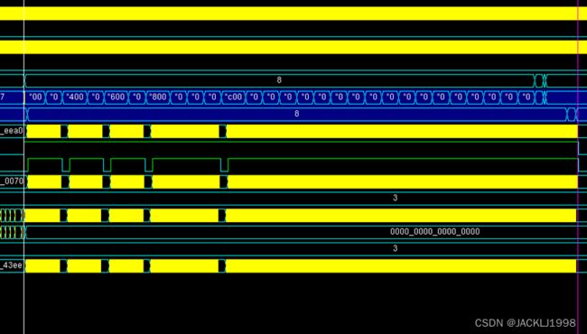
- Transfer size 2048*4 Bytes, burst size 4096 Bytes, take 4100cycles
- Transfer size 2048*4 Bytes, burst size 2048 Bytes, take 4101cycles
- Transfer size 2048*4 Bytes, burst size 256 Bytes, take 4351cycles
- Transfer size 2048*4 Bytes, burst size 64 Bytes, take 4524cycles
- TODO:WHY burst size need more than 64Bytes,if not,transformation will delay and can not be done.
- XILINX CDMA
【原创】ZYNQ AXIDMA详解(一) - 霸天虎1108 - 博客园 (cnblogs.com)
AXI Central DMA - 云+社区 - 腾讯云 (tencent.com)
- TileLink to AXI4
TL2AXI.pdf (sifive.com)
- AXI protocol
An introduction to AMBA AXI (arm.com)
![]()
- Note: The AXI protocol is a point-to-point specification, not a bus specification. Therefore, it describes only the signals and timing between interfaces.
- 注意:每个channel都是单向的,因此需要一个单独的写入响应通道将响应传回给manage。 但是,不需要读取响应通道,因为读取响应是作为读取数据通道的一部分传递的。
- 使用单独的地址和数据通道进行读写传输有助于最大化接口的带宽。 读写通道组之间没有时序关系。 这意味着读取序列可以与写入序列同时发生。
- Channel B ,B 代表bufferd,因为slave的响应发生在所有写入完成之后。
- AXI Interconnects Tutorial: Multiple AXI Masters and Slaves in Digital Logic - Technical Articles (allaboutcircuits.com)
Master ----- Interconnect(crossbar:arbiter+decoder) ----- slave
- Diplomatic Widgets
TLBuffer
- TLBuffer 是一个FIFO constructor.
- TL2AXI4和AXI42TL的实现
TL2AXI4
(AXI4-Crossbar-input-slave-ports
:= AXI4Buffer() --->FIFO(width: 2) in each channel
:= AXI4UserYanker() --->将带有user字段的AXI4总线转换成没有user字段的AXI4总线
:= AXI4Deinterleaver(sbus.blockBytes)---> 用于处理AXI4总线不同id的交错响应,对响应进行重排序,以使得每个id的响应都是连续的
:= AXI4IdIndexer(params.idBits)---> 用于限制输出AXI4总线的id位宽
:= TLToAXI4()
:= TLWidthWidget(sbus.beatBytes)
:= TL-Crossbar-output-master-ports)
- 步骤一:Manager端在TileLink总线上发起请求,Manager端为TileLink总线发起请求端;
- 步骤二:经过TLToAXI4模块将TileLink转换为AXI4,将A通道上的事务对应到相应的AXI4通道;
- 步骤三:经过AXI4IdIndexer模块,AXI4总线的id位宽被固定;当输入的id位宽小于等于限制的输出id位宽,则直接将输入信号输出;当输入的id位宽大于限制的输出id位宽,则将超出的id位存储于AXI4的user字段;
- 步骤四:经过AXI4Deinterleaver模块,在请求消息传递过程中,不对数据进行操作;
- 步骤五:经过AXI4UserYanker模块将带有user字段的AXI4总线转换成不带user字段的AXI4总线;user字段被保存在与id关联的队列中;
- 步骤六:经过AXI4Buffer模块,对AXI4总线上请求消息进行缓存;
- 步骤七:Slaver端响应请求,回传响应消息;Slaver端为AXI4总线响应端;
- 步骤八:AXI4Buffer模块缓存响应消息;
- 步骤九:AXI4UserYanker模块根据响应消息中的id提取出user字段,将不带user字段的AXI4总线转换成带user字段的AXI4总线;
- 步骤十:由于不同AXI4 id的响应可能会交错,经过AXI4Deinterleaver模块对响应进行重排序,使得每个id的响应都是连续的;
- 步骤十一:经过AXI4IdIndexer模块,若user字段中存在id位,则将其补充回响应消息的id位;
- 步骤十二:经过TLToAXI4模块,将在AXI4总线上的读数据和写响应通道数据映射回TileLink总线上;
- 步骤十三:将在TileLink总线上的响应消息回传给Manager。
AXI42TL
TL-Crossbar-input-slave-ports
:= TLBuffer(BufferParams.default)
:= TLFIFOFixer(TLFIFOFixer.all)--->
:= TLWidthWidget(params.beatBytes)---> Width Converter
:= AXI4ToTL()
:= AXI4UserYanker(Some(1 << (params.sourceBits - fifoBits - 1)))
:= AXI4Fragmenter()--->将较大的事务切分成多个较小的事务,以缩小TileLink的最大逻辑传输
:= AXI4IdIndexer(fifoBits)
:*= AXI4-Crossbar-output-master-ports
- rocketchip添加axi4-RailBus
在系统system构建完成之后,通过SIMAXIMEM和TestHarness添加了一条axi4总线,并且挂载了AXI-MEM作为slave.
- 将DMA改成axi4协议接口,实现同时读写
- i. AXI4的burst
深入 AXI4 总线(C0)旧版存档:突发传输机制 - 知乎 (zhihu.com)
LEN是指一个burst里transfer的个数为2^LEN,只有8bits,所以最大传输256*2^size bits。
SIZE指一个transfer的bit数为2^size bits
AWBURST代表三种不同的burst type:分别为 FIXED,INCR 以及 WRAP。使用 2 位二进制表示。
- FIXED 类型适合对某个固定地址进行数据更新,比如向一个 almost full 的 fifo 更新数据。
- INCR 类型最为常用,后续的数据的存储地址在初始地址的基础上,以突发传输宽度进行递增,适合对于 RAM 等 mapped memory 存储介质进行读写操作。
- WRAP 模式比较特殊,除了初始地址外,还有最高地址的界限。在最大地址以下,WRAP 与 INCR 类型完全相同,地址递增,但达到最高地址后,地址直接回到起始地址,再进行递增,就这样循环往复。数据手册上表示,WRAP 适合对 cache 的访问。
AXI4 burst最大256*XLENbits, Tilelink burst最大4096Bytes,所以将修改测试了一下外挂SIMAXIMem的读写没问题。
- ii. Rocket-chip AXI4 max burst size 修改
Mmio-port的burst size修改
这样修改后可以支持AXI4协议支持的最大burst大小,但是会有相应的buffer生成,有面积消耗。
- iii. 方案一:TL-AXI4实现AXI4DMA
- iv. 方案二:直接用custom AXI4 node连接Xbar


