20200409_W_Fluid-Structure Interaction and OpenSeesPy
Abastract
基于OpenSees的最新进展,本项目的目标是扩大Ops的Python功能,并基于粒子有限元方法(PFEM)进一步发展其流固耦合(FSI)仿真功能。首先,在OpenSees中基于Python脚本开发了FSI模块。在OpenSees中完成FSI模拟功能,通过整合之前已存在的单元和材料命令在有限的范围内添加了Python命令,例如,线弹性三角形单元。Python框架下的数百种本构模型和元素公式,对于FSI和一般OpenSees的使用仍有待完成。OpenSees中的Tcl语言基于字符串,功能强大且易于学习,但不适合用于数学计算;工程应用脚本语言的最新趋势接受了更通用的科学语言,例如,Python,演变成拥有大量用于数值计算,数据分析,科学的可视化和网站开发。这些库可以与FSI模拟用于海啸分析。将OpenSees扩展到Python将有助于OpenSees与科学计算社区的新脚本开发保持同步,并且使该框架更易于可能学习过Python的研究生使用。
Introduction
海啸、风暴潮和飓风造成的近期危害已造成重大破坏到沿海基础设施和桥梁,例如2005年的卡特里娜飓风(Padgett等,2008年)和2011年东北地震和海啸(Suppasri等人,2014年)。确实,整个美国西海岸容易受到遥远的海啸和潜在的强烈地震的影响与卡斯卡迪亚俯冲带有关,随后是海啸影响。许多研究人员要求获得有关流固耦合的信息(FSI)OpenSees的仿真功能。为了支持太平洋地震工程研究中心(PEER)的基于性能的海啸工程计划(PBTE),现有的基于性能的地震工程(PBEE)方法已使用OpenSees平台扩展到FSI,以增强其建模能力,计算的准确性和效率。
作为PEER的主要仿真工具,OpenSees的重点主要放在地震工程与非线性结构分析。以现有功能为基础在OpenSees中,该项目的首要目标是进一步开发FSI模块将海啸危害纳入建筑物和桥梁的分析和评估中,以及连续地震和海啸的危害。 FSI仿真功能的OpenSees基于粒子有限元方法(PFEM),这是一种基于拉格朗日的方法,符合现有的结构公式在OpenSees中。通过使用PFEM,可以轻松地将FSI分析添加到任何现有的OpenSees脚本,无需修改结构模型。这对于在OpenSees中开发了结构模型并想要测试他们的研究人员有海啸负荷的模型。
除了开发FSI模块外,该项目的第二个目标是扩展OpenSees的Python脚本功能,并使框架更加新一代用户可以访问。从一开始,OpenSees中的FSI模块一直基于Python脚本编写。要在OpenSees,Python中完成FSI仿真为有限数量的现有元素和材料添加了命令
命令,例如线弹性三角形单元和梁柱单元Concrete01 / Steel01纤维段;也就是说,数百种本构模型和元素公式仍需纳入Python的保护范围内。虽然原来OpenSees中的脚本语言Tcl是基于字符串的,功能强大且易于学习,不是适用于数学计算。用于工程应用程序的脚本语言的最新趋势已经包含了更通用的科学语言,例如Python。已发展成为一个拥有大量用于数值计算,数据的库的大型社区分析,科学可视化和网站开发。将OpenSees扩展到Python将确保OpenSees在添加新脚本时与时俱进由科学计算社区提供。
该报告将分为三个主要章节。第1章介绍背景理论和算法,以及用于FSI分析的控制方程式。实施OpenSees中FSI模块的功能及其与现有框架的关系将在第2章中进行介绍。第3章着重于OpenSees,从中实现Python解释器。
2 Fluid-Structure Interaction
使用粒子有限元方法开发了OpenSees中的FSI仿真(PFEM)。由于拉格朗日描述已在结构分析中广泛使用,基于拉格朗日的PFEM可以自然地与现有的结构公式结合在OpenSees中,导致了用于控制FSI的方程的整体系统(Oñate等。2004; Cremonesi等。 2010)。整体方法解决了混合流体和结构域同时进行,并确保整个结构域之间的平衡和兼容性域之间的FSI接口。
使用PFEM的优势在于它克服了耦合的复杂性流体和结构方法通过交错方案分别进行(Oñate等人,2011)。PFEM对流体-结构边界的确切位置也不太敏感,这可以是域分解方法的缺点。这两个因素,容易耦合FSI边界的能力和任意位置,对于建筑物以及构成沿海基础设施的桥梁尤其重要。在地震工程中最初开发OpenSees,通常将结构表示为可以响应地面运动任意移动的框架元素。OpenSees中有数百种其他类型的元素,研究人员正在不断添加新元素。使用PFEM的优势在于它可以将FSI嵌入到OpenSees框架,无需修改元素。
使用PFEM的另一个优势是波载荷的精确近似以及流体与结构之间的相互作用。在海啸期间,互动海啸和建筑物之间的关系可能非常复杂。波浪载荷不能可以很容易地用初始波速和高度来确定,但是很大程度上取决于结构尺寸和响应。粒子用于跟踪流体的运动,包括大的流体、破碎波和结构周围的发散流。结构可能会受到不同方向的影响,有时甚至会受到相反方向的海啸方向的影响。
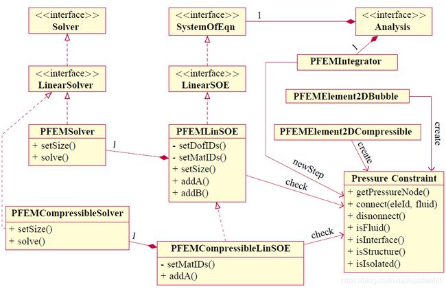
考虑到OpenSees的用户主要由结构和岩土工程组成工程师,OpenSees中的FSI模块经过精心设计,以便用户可以最大程度地减少通过轻松地将模块整合到他们的FSI分析中所需的工作量当前的结构模型。用户应该能够在其现有脚本中添加几行包括流体模型并设置FSI分析选项而不必担心网格划分,计算和交互算法。本章介绍PFEM的整体控制系统的基本控制方程和有限元离散化FSI的方程和分数步求解器,以及FSI的网格更新算法流体和结构分析。
2.1 Governing Equations
Conservation of linear momentum is enforced in both the fluid and structural domains, and can be written in the updated Lagrangian formulation as
ρ v ˙ i = ∂ σ i j ∂ x j + ρ b i \rho \dot{v}_{i}=\frac{\partial \sigma_{i j}}{\partial x_{j}}+\rho b_{i} ρv˙i=∂xj∂σij+ρbi
where ρ \rho ρ is the material density, v i v_i vi, x i x_i xi, and b i b_i bi are the velocity, coordinates, and body acceleration vectors, respectively, and σ i j \sigma_{ij} σij is the Cauchy stress tensor. Neumann boundary conditions prescribe normal stresses on the surface, Γ t \Gamma_t Γt,
σ i j n j = t i \sigma_{i j} n_{j}=t_{i} σijnj=ti
where t i t_i ti is the surface traction, and n j n_j nj is the unit vector normal to the boundary surface. The velocity and displacement are dependent variables of coordinates, and Dirichlet boundary conditions are imposed on displacements on the surface, Γ v \Gamma_v Γv.
u i = u i p u_{i}=u_{i}^{p} ui=uip
where u i p u^p_i uip is the prescribed displacements. The intersection between Γ t \Gamma_t Γt and Γ v \Gamma_v Γv is the empty set, and their union is the entire boundary of the computational domain. As the simulation proceeds, the relationship between coordinates and displacements is
x i = x i 0 + u i x_{i}=x_{i}^{0}+u_{i} xi=xi0+ui
where x i 0 x^0_i xi0 is the initial coordinates. The stress–strain relationship for the structural domain is assumed to be a general nonlinear function of displacement and velocity
σ i j = σ i j ( u i , v i ) \sigma_{i j}=\sigma_{i j}\left(u_{i}, v_{i}\right) σij=σij(ui,vi)
With this general form, it is straightforward to incorporate hysteresis and viscosity materials in OpenSees (Simo and Hughes 1998). For Newtonian fluids, the Cauchy stress is decomposed into spherical and deviatoric portions.
σ i j = s i j − p δ i j \sigma_{i j}=s_{i j}-p \delta_{i j} σij=sij−pδij
where δ i j \delta_{ij} δij is the Kronecker delta, and KaTeX parse error: Undefined control sequence: \sigama at position 5: p = \̲s̲i̲g̲a̲m̲a̲_{ii}/3 is the average stress (pressure), which is positive for compression. The deviatoric stress s i j s_{ij} sij is defined in terms of the strain rate by
s i j = 2 μ ( ε i j − 1 3 ε v δ i j ) s_{i j}=2 \mu\left(\varepsilon_{i j}-\frac{1}{3} \varepsilon_{v} \delta_{i j}\right) sij=2μ(εij−31εvδij)
where μ \mu μ is the viscosity, and ϵ i j \epsilon_{ij} ϵij is the strain rate tensor,
ε i j = 1 2 ( ∂ v i ∂ x j + ∂ v j ∂ x i ) \varepsilon_{i j}=\frac{1}{2}\left(\frac{\partial v_{i}}{\partial x_{j}}+\frac{\partial v_{j}}{\partial x_{i}}\right) εij=21(∂xj∂vi+∂xi∂vj)
Conservation of mass in the structural domain can be written as
ρ J = ρ 0 \rho J=\rho_{0} ρJ=ρ0
where ρ 0 \rho_0 ρ0 is the density in the undeformed configuration, and J J J is the determinant of the deformation tensor as defined in Mase et al. (2009). Conservation of mass can be expressed as the divergence of the velocity field equal to the time rate of change in pressure,
ε v = ε i i = ∂ v i ∂ x i = − 1 κ p ˙ \varepsilon_{v}=\varepsilon_{i i}=\frac{\partial v_{i}}{\partial x_{i}}=-\frac{1}{\kappa} \dot{p} εv=εii=∂xi∂vi=−κ1p˙
where κ \kappa κ is the bulk modulus. For incompressible flow, κ = ∞ \kappa= \infty κ=∞, Equation (2.10) becomes
ε v = ε i i = ∂ v i ∂ x i = 0 \varepsilon_{v}=\varepsilon_{i i}=\frac{\partial v_{i}}{\partial x_{i}}=0 εv=εii=∂xi∂vi=0
Nonlinear structural response is defined by the governing equations of linear momentum Equation (2.1), a general constitutive Equation (2.5), and mass conservation Equation (2.9). Likewise, the equations of linear momentum Equation (2.1), constitution Equation (2.7), and mass Equation (2.10) define the Newtonian fluid response.
2.2 Finite-Element Discretization
2.2.1 Structural equations
One of the challenges for the FSI computation in OpenSees is to make the FSI work with all elements in the framework. With this in mind, no specific structural elements should be assumed to discretize the structural governing equations in Equations (2.1), (2.5), and (2.9). By assuming a general structural element and applying the standard Galerkin formulation of the weighted residual method (Zienkiewicz et al. 2005), the discretized structural equations can be written as
ε v = ε i i = ∂ v i ∂ x i = 0 \varepsilon_{v}=\varepsilon_{i i}=\frac{\partial v_{i}}{\partial x_{i}}=0 εv=εii=∂xi∂vi=0
where v s v_s vs is the structural velocities, and M s M_s Ms, K s K_s Ks, and F s i n t F^{int}_s Fsint
and F s F_s Fs are the structural mass matrix, damping matrix, and internal and external force vectors, respectively. The internal force vector is a general nonlinear function of displacements and velocities that accounts for material and geometric nonlinearity for any type of element in OpenSees, such as beam–column configurations, shells, and plates.
Fluid Equation
The same finite-element procedure can be applied to the equations governing fluids in Equations (2.1), (2.7), and (2.10). The MINI element (Arnold et al. 1984) is used for a mixed formulation of velocity and pressure to discretize the fluid domain. As a stable linear element, the MINI element overcomes the Inf-Sup condition for fully or nearly incompressible fluids (Gresho 1998) shown in Figure 2.1
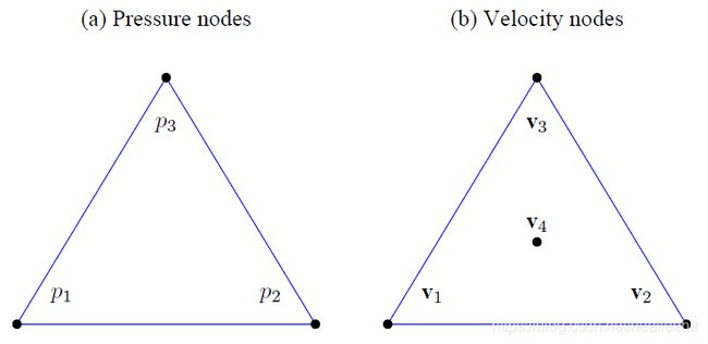
The bubble node in Figure 2.1(b) enhances the velocity field with a cubic term and adds stability for the pressure interpolation. The discretized fluid equations can be written as
M f v ˙ f + K f v f + F f i n t = F f \mathbf{M}_{f} \dot{\mathbf{v}}_{f}+\mathbf{K}_{f} \mathbf{v}_{f}+\mathbf{F}_{f}^{i n t}=\mathbf{F}_{f} Mfv˙f+Kfvf+Ffint=Ff
M p p ˙ + G f T v f = 0 \mathbf{M}_{p} \dot{\mathbf{p}}+\mathbf{G}_{f}^{T} \mathbf{v}_{f}=\mathbf{0} Mpp˙+GfTvf=0
where v f v_f vf and p p p are the fluid velocities and pressures, and M f M_f Mf, K f K_f Kf , and F f i n t F^{int}_f Ffint and F f F_f Ff are the fluid mass matrix, viscous matrix, and internal and external force vectors, respectively. The fluid internal force vector corresponds to the pressure gradients.
F f i n t = − G f p \mathbf{F}_{f}^{i n t}=-\mathbf{G}_{f} \mathbf{p} Ffint=−Gfp
where G f G_f Gf is the gradient operator, and the pressure mass matrix M p M_p Mp is valid only for quasiincompressible flow, whose bulk modulus, κ \kappa κ, is finite.
2.2.3 Monolithic System
As a monolithic system that governs FSI, the compatibility along the interface of FSI is satisfied through the nodes connected to both the fluid and structural domains. These nodes are identified as interface nodes, whose contributions appear in both fluid and structural equations. For the structural equation, the interface equations are extracted from Equation
(2.12) and assigned additional i i i and s s s subscripts
M s s v ˙ s + M s i v ˙ i + K s s v s + K s i v i + F s i n t = F s M i s v ˙ s + M i i s v ˙ i + K i s v s + K i i s v i + F i i n t = F i s \begin{aligned} \mathbf{M}_{s s} \dot{\mathbf{v}}_{s}+\mathbf{M}_{s i} \dot{\mathbf{v}}_{i}+\mathbf{K}_{s s} \mathbf{v}_{s}+\mathbf{K}_{s i} \mathbf{v}_{i}+\mathbf{F}_{s}^{i n t} &=\mathbf{F}_{s} \\ \mathbf{M}_{i s} \dot{\mathbf{v}}_{s}+\mathbf{M}_{i i}^{s} \dot{\mathbf{v}}_{i}+\mathbf{K}_{i s} \mathbf{v}_{s}+\mathbf{K}_{i i}^{s} \mathbf{v}_{i}+\mathbf{F}_{i}^{i n t} &=\mathbf{F}_{i}^{s} \end{aligned} Mssv˙s+Msiv˙i+Kssvs+Ksivi+FsintMisv˙s+Miisv˙i+Kisvs+Kiisvi+Fiint=Fs=Fis
where _ vi and vi are the acceleration and velocity vectors of the interface nodes, respectively. Similarly, the interface equations are extracted from Equations (2.13) and (2.14) for the fluid domain and given additional i and j subscripts
M s s v ˙ s + M s i v ˙ i + K s s v s + K s i v i + F s i n t = F s M i s v ˙ s + M i i s v ˙ i + K i s v s + K i i s v i + F i i n t = F i s \begin{aligned} \mathbf{M}_{s s} \dot{\mathbf{v}}_{s}+\mathbf{M}_{s i} \dot{\mathbf{v}}_{i}+\mathbf{K}_{s s} \mathbf{v}_{s}+\mathbf{K}_{s i} \mathbf{v}_{i}+\mathbf{F}_{s}^{i n t} &=\mathbf{F}_{s} \\ \mathbf{M}_{i s} \dot{\mathbf{v}}_{s}+\mathbf{M}_{i i}^{s} \dot{\mathbf{v}}_{i}+\mathbf{K}_{i s} \mathbf{v}_{s}+\mathbf{K}_{i i}^{s} \mathbf{v}_{i}+\mathbf{F}_{i}^{i n t} &=\mathbf{F}_{i}^{s} \end{aligned} Mssv˙s+Msiv˙i+Kssvs+Ksivi+FsintMisv˙s+Miisv˙i+Kisvs+Kiisvi+Fiint=Fs=Fis
where the off-diagonal terms in the mass and viscous matrices, Mfi, Mif , Kfi, Kif , have disappeared due to diagonalization of the mass matrix and formulation of the MINI element. The interface equations in Equations (2.17) and (2.19) are combined to satisfy equilibrium on the FSI interface. The combined monolithic system for the FSI can be written as
M s s v ˙ s + M s i v ˙ i + K s s v s + K s i v i + F s i n t = F s M i s v ˙ s + K i s v s + M i i v ˙ i + K i i v i + F i i n t − G i p = F i M f f v ˙ f + K f f v f − G f p = F f M p p ˙ + G f T v f + G i T v i = 0 \begin{aligned} \mathbf{M}_{s s} \dot{\mathbf{v}}_{s}+\mathbf{M}_{s i} \dot{\mathbf{v}}_{i}+\mathbf{K}_{s s} \mathbf{v}_{s}+\mathbf{K}_{s i} \mathbf{v}_{i}+\mathbf{F}_{s}^{i n t} &=\mathbf{F}_{s} \\ \mathbf{M}_{i s} \dot{\mathbf{v}}_{s}+\mathbf{K}_{i s} \mathbf{v}_{s}+\mathbf{M}_{i i} \dot{\mathbf{v}}_{i}+\mathbf{K}_{i i} \mathbf{v}_{i}+\mathbf{F}_{i}^{i n t}-\mathbf{G}_{i} \mathbf{p} &=\mathbf{F}_{i} \\ \mathbf{M}_{f f} \dot{\mathbf{v}}_{f}+\mathbf{K}_{f f} \mathbf{v}_{f}-\mathbf{G}_{f} \mathbf{p} &=\mathbf{F}_{f} \\ \mathbf{M}_{p} \dot{\mathbf{p}}+\mathbf{G}_{f}^{T} \mathbf{v}_{f}+\mathbf{G}_{i}^{T} \mathbf{v}_{i} &=\mathbf{0} \end{aligned} Mssv˙s+Msiv˙i+Kssvs+Ksivi+FsintMisv˙s+Kisvs+Miiv˙i+Kiivi+Fiint−GipMffv˙f+Kffvf−GfpMpp˙+GfTvf+GiTvi=Fs=Fi=Ff=0
where Mii, Kii, and Fi are the combined matrices and vector at the interface
M i i = M i i s + M i i f K i i = K i i s + K i i f F i = F i s + F i f \begin{aligned} \mathbf{M}_{i i} &=\mathbf{M}_{i i}^{s}+\mathbf{M}_{i i}^{f} \\ \mathbf{K}_{i i} &=\mathbf{K}_{i i}^{s}+\mathbf{K}_{i i}^{f} \\ \mathbf{F}_{i} &=\mathbf{F}_{i}^{s}+\mathbf{F}_{i}^{f} \end{aligned} MiiKiiFi=Miis+Miif=Kiis+Kiif=Fis+Fif
The combined system in Equations (2.21), (2.22), (2.23), and (2.24) should be further discretized in the time domain and solved using a nonlinear algorithm, which will be introduced in the following sections.
Time-Domain Discretization
A Backward Euler time integration is employed for the time-domain discretization. The
displacement and acceleration are expressed in terms of the velocity at the current time
step, and the displacement and velocity at the previous time step,
Nonlinear Solution Algorithm
The combined system in Equations (2.21), (2.22), (2.23), and (2.24) is composed of nonlinear equations because of the general nonlinear material for structures and geometric nonlinearity for the fluid and structure. Solution of the nonlinear equations is obtained using the Newton–Raphson algorithm, which writes equations in the residual form:
r s = F s − ( M s s v ˙ s + K s s v s + M s i v ˙ i + K s i v i + F s i n t ) r i = F i − ( M i s v ˙ s + K i s v s + M i i v ˙ i + K i i v i + F i i n t − G i p ) r f = F f − ( M f f v ˙ f + K f f v f − G f p ) r p = − ( M p p ˙ + G f T v f + G i T v i ) \begin{aligned} &\mathbf{r}_{s}=\mathbf{F}_{s}-\left(\mathbf{M}_{s s} \dot{\mathbf{v}}_{s}+\mathbf{K}_{s s} \mathbf{v}_{s}+\mathbf{M}_{s i} \dot{\mathbf{v}}_{i}+\mathbf{K}_{s i} \mathbf{v}_{i}+\mathbf{F}_{s}^{i n t}\right)\\ &\begin{aligned} \mathbf{r}_{i} &=\mathbf{F}_{i}-\left(\mathbf{M}_{i s} \dot{\mathbf{v}}_{s}+\mathbf{K}_{i s} \mathbf{v}_{s}+\mathbf{M}_{i i} \dot{\mathbf{v}}_{i}+\mathbf{K}_{i i} \mathbf{v}_{i}+\mathbf{F}_{i}^{i n t}-\mathbf{G}_{i} \mathbf{p}\right) \\ \mathbf{r}_{f} &=\mathbf{F}_{f}-\left(\mathbf{M}_{f f} \dot{\mathbf{v}}_{f}+\mathbf{K}_{f f} \mathbf{v}_{f}-\mathbf{G}_{f} \mathbf{p}\right) \\ \mathbf{r}_{p} &=-\left(\mathbf{M}_{p} \dot{\mathbf{p}}+\mathbf{G}_{f}^{T} \mathbf{v}_{f}+\mathbf{G}_{i}^{T} \mathbf{v}_{i}\right) \end{aligned} \end{aligned} rs=Fs−(Mssv˙s+Kssvs+Msiv˙i+Ksivi+Fsint)rirfrp=Fi−(Misv˙s+Kisvs+Miiv˙i+Kiivi+Fiint−Gip)=Ff−(Mffv˙f+Kffvf−Gfp)=−(Mpp˙+GfTvf+GiTvi)
Following the procedure of the Newton–Raphson algorithm, the derivative of the residual is obtained with respect to the velocity and pressure unknowns, at which point the velocity and pressure increments can be computed as follows:
K T [ Δ v s Δ v i Δ v f Δ p ] = [ r s r i r f r p ] \mathbf{K}_{T}\left[\begin{array}{c} \Delta \mathbf{v}_{s} \\ \Delta \mathbf{v}_{i} \\ \Delta \mathbf{v}_{f} \\ \Delta \mathbf{p} \end{array}\right]=\left[\begin{array}{c} \mathbf{r}_{s} \\ \mathbf{r}_{i} \\ \mathbf{r}_{f} \\ \mathbf{r}_{p} \end{array}\right] KT⎣⎢⎢⎡ΔvsΔviΔvfΔp⎦⎥⎥⎤=⎣⎢⎢⎡rsrirfrp⎦⎥⎥⎤
where KT is the combined tangent stiffness matrix for the structural interface and fluid velocities and pressures.
K T = − ( ∂ [ r s r i r j r p ] ∂ [ v s v i v j p ] ) − 1 = [ K T s s K T s i 0 0 K T i s K T i i 0 − G i 0 0 K T f f − G f 0 G i T G f T K T p p ] K_T=-\left(\frac{\partial \left[ \begin{array}{cccc} r_s & r_i & r_j & r_p\end{array}\right]}{\partial \left[ \begin{array}{cccc} v_s & v_i & v_j & p\end{array}\right]} \right)^{-1} = \left[\begin{array}{cccc} \mathbf{K}_{T s s} & \mathbf{K}_{T s i} & \mathbf{0} & \mathbf{0} \\ \mathbf{K}_{T i s} & \mathbf{K}_{T i i} & \mathbf{0} & -\mathbf{G}_{i} \\ \mathbf{0} & \mathbf{0} & \mathbf{K}_{T f f} & -\mathbf{G}_{f} \\ \mathbf{0} & \mathbf{G}_{i}^{T} & \mathbf{G}_{f}^{T} & \mathbf{K}_{T p p} \end{array}\right] KT=−(∂[vsvivjp]∂[rsrirjrp])−1=⎣⎢⎢⎡KTssKTis00KTsiKTii0GiT00KTffGfT0−Gi−GfKTpp⎦⎥⎥⎤
The matrices K T s s K_{Tss} KTss and K T s i K_{Tsi} KTsi are tangents of the structural residual to the structural and interface velocities:
K T s s = − ∂ r s ∂ v s = 1 Δ t M s s + K s s + Δ t ∂ F s i n t ∂ v s K T s i = − ∂ r s ∂ v i = 1 Δ t M s i + K s i + Δ t ∂ F s i n t ∂ v i \begin{aligned} &\mathbf{K}_{T s s}=-\frac{\partial \mathbf{r}_{s}}{\partial \mathbf{v}_{s}}=\frac{1}{\Delta t} \mathbf{M}_{s s}+\mathbf{K}_{s s}+\Delta t \frac{\partial \mathbf{F}_{s}^{i n t}}{\partial \mathbf{v}_{s}}\\ &\mathbf{K}_{T s i}=-\frac{\partial \mathbf{r}_{s}}{\partial \mathbf{v}_{i}}=\frac{1}{\Delta t} \mathbf{M}_{s i}+\mathbf{K}_{s i}+\Delta t \frac{\partial \mathbf{F}_{s}^{i n t}}{\partial \mathbf{v}_{i}} \end{aligned} KTss=−∂vs∂rs=Δt1Mss+Kss+Δt∂vs∂FsintKTsi=−∂vi∂rs=Δt1Msi+Ksi+Δt∂vi∂Fsint
Likewise, the matrices K T i s K_{Tis} KTis and K T i i K_{Tii} KTii are tangents of the interface residual to the structural and interface velocities:
K T i s = − ∂ r i ∂ v s = 1 Δ t M i s + K i s + Δ t ∂ F i i n t ∂ v s K T i i = − ∂ r i ∂ v i = 1 Δ t M i i + K i i + Δ t ∂ F i i n t ∂ v i \begin{aligned} &\mathbf{K}_{T i s}=-\frac{\partial \mathbf{r}_{i}}{\partial \mathbf{v}_{s}}=\frac{1}{\Delta t} \mathbf{M}_{i s}+\mathbf{K}_{i s}+\Delta t \frac{\partial \mathbf{F}_{i}^{i n t}}{\partial \mathbf{v}_{s}}\\ &\mathbf{K}_{T i i}=-\frac{\partial \mathbf{r}_{i}}{\partial \mathbf{v}_{i}}=\frac{1}{\Delta t} \mathbf{M}_{i i}+\mathbf{K}_{i i}+\Delta t \frac{\partial \mathbf{F}_{i}^{i n t}}{\partial \mathbf{v}_{i}} \end{aligned} KTis=−∂vs∂ri=Δt1Mis+Kis+Δt∂vs∂FiintKTii=−∂vi∂ri=Δt1Mii+Kii+Δt∂vi∂Fiint
The matrix K T f f K_{Tff} KTff, which is the tangent of the fluid residual to the fluid velocity, is not connected to structural and interface tangents:
K T f f = − ∂ r f ∂ v f = 1 Δ t M f f + K f f \mathbf{K}_{T f f}=-\frac{\partial \mathbf{r}_{f}}{\partial \mathbf{v}_{f}}=\frac{1}{\Delta t} \mathbf{M}_{f f}+\mathbf{K}_{f f} KTff=−∂vf∂rf=Δt1Mff+Kff
The combined system, shown in Equation (2.41), connects the structural and fluid domains through the interface pressure gradients matrix G i G_i Gi, which represents the wave loading applied on the structures. The matrix K T p p K_{Tpp} KTpp is the tangent of the pressure residual to the fluid pressures, which accounts for compressibility and stability of the fluid formulation.
K T p p = − ∂ r p ∂ v p = 1 Δ M p K_{Tpp}=-\frac{\partial r_p}{\partial v_p}=\frac{1}{\Delta }M_p KTpp=−∂vp∂rp=Δ1Mp
In each iteration of the nonlinear solution procedure, the velocity and pressure increments are computed by Equation (2.40), and the displacements, velocities, accelerations, and pressures are updated, as shown in Equation (2.30)–Equation (2.35). The convergence is tested by checking the increment and residual vectors in Equation (2.40). If they are smaller than preset tolerances, the combined system in Equations (2.36), (2.37), (2.38), and (2.39) is considered to be satisfied, and the solutions are obtained for the current time step.
2.5 Various Solvers for FSI in OpenSees
The monolithic matrix in Equation (2.41) is ill-conditioned due to the coupling of the velocity and pressure fields, making it difficult to obtain a stable numerical solution for the incremental velocities and pressures. There are two solvers available in OpenSees to solve Equation (2.40) efficiently, with a stable solution depending on assumptions of the fluid. Each of them will be introduced in the following sections.
2.5.1 Incompressible fractional step solver
2.5.2 Unified fractional stepsolver
2.6 Domain Meshing for FSI
2.6.1 Moving mesh method
A Delaunay Triangulation (DT) is needed to construct the mesh, based only on the nodal positions in the previous time step. Since the computing effort of a DT has been proven to be minimal (Watson 1981), it is possible to remesh in every time step. The procedure of the moving mesh method is demonstrated in the figures below.

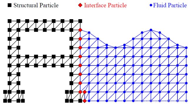
The advantage of the moving mesh is twofold: it is efficient in terms of mesh updating, and it is flexible for any geometry of the structure and boundary conditions; however, as shown in Figure 2.4, small elements are formed since it is inevitable that fluid particles move close to each other. In a Lagrangian formulation, the smallest element controls the size of the time steps. As a result, a strict limit should be placed on the time step sizes in order to obtain a converged solution. This limitation can be overcome by the following background mesh method.
2.6.2 Background mesh method
The background mesh method separates the functions of the finite-element nodes and moving particles so that finite-element nodes do not have to move with the flow and can be fixed in the background. The fixed mesh circumvents the problem of small and distorted elements in the moving mesh, but needs more particles to transport the fluid properties.
A background mesh method with a fixed finite-element mesh has been used by Becker et al. (2015) for rapid generation of mesh in fluid–structure interaction (FSI) analysis. Since triangular structural and fluid elements are used together in the fixed mesh, the structural and fluid domains are uniformly meshed; therefore, no local remeshing is needed around structures. If a general structure, such as coastal infrastructure, cannot always be modeled with a fixed mesh, then the local mesh around the structure should be reconstructed to connect the structure to the fixed mesh. The modified background mesh mixes the fixed and moving mesh, benefiting from the use of both methods.
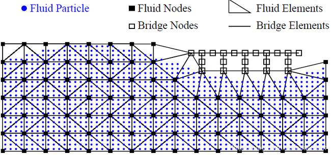
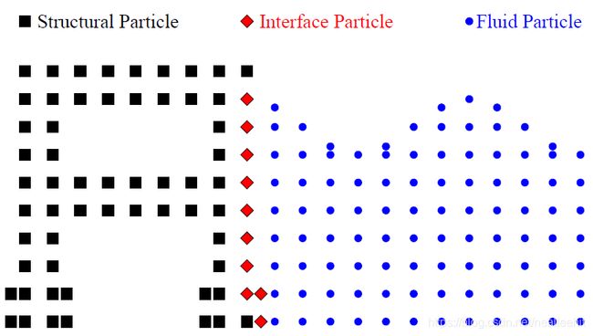
As shown in Figure 2.5, a cloud of fluid particles are placed on the background. Based on the locations of the fluid particles, a fixed background mesh is created with fluid elements and nodes. As shown in Figure 2.6, the fluid particles and nodes are separated in the fixed mesh. The fluid nodes are always fixed on the grids in the background, and the fluid elements are of good quality.
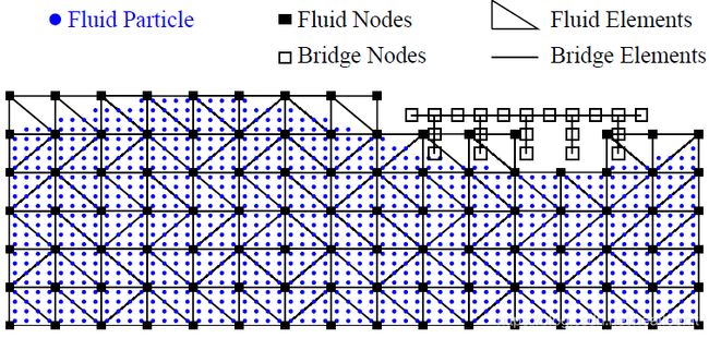
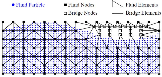
As shown in Figure 2.7, a bridge structure in placed on the fixed mesh. Since part of the structural mesh overlaps with the fixed mesh, the local fixed mesh around the structure has to be removed and remeshed. Then a DT can be performed in the local area; note that some triangles are obviously not part of the mesh; see Figure 2.8. Instead of using the Alpha Shape Method, an easy and straightforward way to identify unnecessary triangles is to find and remove the empty triangles that have no particle. The final background mesh is shown in Figure 2.9.
All the background information, governing equations, solution algorithms, numerical solvers, and mesh updating methods have been introduced in this chapter. In the next chapter, examples implementing the FSI in OpenSees will be introduced.
