激光雷达与相机融合(一)

一.激光雷达点云俯视图提取

文末有相应的代码数据包免费下载链接。
将激光雷达点云投影到俯视图平面上,同时将距离的远近利用颜色表示出来。
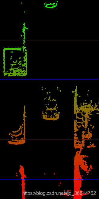
激光雷达与相机融合(一)_第1张图片

激光雷达与相机融合(一)_第2张图片
这里的滤除地面只是简单的利用高度值将地面去除。会存在效果不好的情况。代码即相应注释。

#include 
#include 
#include 
#include 
#include 

#include "structIO.hpp"

using namespace std;

void showLidarTopview()
{
    std::vector<LidarPoint> lidarPoints;
    readLidarPts("../dat/C51_LidarPts_0000.dat", lidarPoints);

    cv::Size worldSize(10.0, 20.0); // width and height of sensor field in m (w,h)
    cv::Size imageSize(1000, 2000); // corresponding top view image in pixel

    // create topview image
    cv::Mat topviewImg(imageSize, CV_8UC3, cv::Scalar(0, 0, 0));

    // plot Lidar points into image
    for (auto it = lidarPoints.begin(); it != lidarPoints.end(); ++it)
     {
         if(it->z < -1.4) //排除靠近地面的点,高度阈值设置为1.4m
             continue;
        
        float xw = (*it).x; // world position in m with x facing forward from sensor
        float yw = (*it).y; // world position in m with y facing left from sensor

        int y = (-xw * imageSize.height / worldSize.height) + imageSize.height;
        int x = (-yw * imageSize.height / worldSize.height) + imageSize.width / 2; //注意图像坐标系与激光雷达坐标系
                                                                                    //图像坐标系位于左上角,x朝右,y朝下
                                                                                    //激光雷达坐标系投影到俯视图式位于图片底边的终点,x朝上,y朝右
        float val = it->x;
        float maxval = worldSize.height;
        int red = min(255, (int)(255*abs((val-maxval)/maxval)));
        int green = min(255, (int)(255*(1-abs((val-maxval)/maxval))));
        cv::circle(topviewImg, cv::Point(x, y), 5, cv::Scalar(0, green, red), -1);
    }
    

    // plot distance markers 绘制标记线
    float lineSpacing = 2.0; // gap between distance markers
    int nMarkers = floor(worldSize.height / lineSpacing);
    for (size_t i = 0; i < nMarkers; ++i)
    {
        int y = (-(i * lineSpacing) * imageSize.height / worldSize.height) + imageSize.height;
        cv::line(topviewImg, cv::Point(0, y), cv::Point(imageSize.width, y), cv::Scalar(255, 0, 0));
    }

    // display image
    string windowName = "Top-View Perspective of LiDAR data";
    cv::namedWindow(windowName, 2);
    cv::imshow(windowName, topviewImg);
    cv::waitKey(0); // wait for key to be pressed
}

int main()
{
    showLidarTopview();
}

二.将激光雷达点云投影到图像上


要将点云投影到图片上,需要知道激光雷达与相机之间的位置转换矩阵以及相机内参。
这里涉及的坐标转换流程是:激光雷达坐标系—》摄像头坐标系—》图像平面坐标系。中间过程相应的就涉及到两个转换矩阵。

在这里插入图片描述
这里采用的KITTI的数据图片,其中(R|T)就是激光雷达到相机的转换矩阵(4X4),P_rect_xx是相机的内参矩阵(3x4),而中间多一个R_rect_00是两个相机之间的转换矩阵(4X4),因为KITTI设备采集车上安装有两个摄像头,为了让多个摄像头的检测画面能够对应,所以需要转换矩阵来将各个摄像头的数据画面转换到相同的平面下,这里所用的R_rect_00就是将左侧灰度摄像头转换到共同平面的转换矩阵。X则代表激光雷达点(4X1)。
激光雷达与相机外参

calib_time: 15-Mar-2012 11:37:16

R: 7.533745e-03 -9.999714e-01 -6.166020e-04 1.480249e-02 7.280733e-04 -9.998902e-01 9.998621e-01 7.523790e-03 1.480755e-02

T: -4.069766e-03 -7.631618e-02 -2.717806e-01

相机与相机外参以及相机内参

calib_time: 09-Jan-2012 13:57:47//使相机图像平面共面,所以只需要旋转矩阵。
R_rect_00: 9.999239e-01 9.837760e-03 -7.445048e-03 -9.869795e-03 9.999421e-01 -4.278459e-03 7.402527e-03 4.351614e-03 9.999631e-01

P_rect_00: 7.215377e+02 0.000000e+00 6.095593e+02 0.000000e+00 0.000000e+00 7.215377e+02 1.728540e+02 0.000000e+00 0.000000e+00 0.000000e+00 1.000000e+00 0.000000e+00

投影结果
激光雷达与相机融合(一)_第3张图片
代码及相应注释

#include 
#include 
#include 
#include 
#include 

#include "structIO.hpp"

using namespace std;
//设置标定参数
void loadCalibrationData(cv::Mat &P_rect_00, cv::Mat &R_rect_00, cv::Mat &RT)
{
    RT.at<double>(0,0) = 7.533745e-03; RT.at<double>(0,1) = -9.999714e-01; RT.at<double>(0,2) = -6.166020e-04; RT.at<double>(0,3) = -4.069766e-03;
    RT.at<double>(1,0) = 1.480249e-02; RT.at<double>(1,1) = 7.280733e-04; RT.at<double>(1,2) = -9.998902e-01; RT.at<double>(1,3) = -7.631618e-02;
    RT.at<double>(2,0) = 9.998621e-01; RT.at<double>(2,1) = 7.523790e-03; RT.at<double>(2,2) = 1.480755e-02; RT.at<double>(2,3) = -2.717806e-01;
    RT.at<double>(3,0) = 0.0; RT.at<double>(3,1) = 0.0; RT.at<double>(3,2) = 0.0; RT.at<double>(3,3) = 1.0;
    
    R_rect_00.at<double>(0,0) = 9.999239e-01; R_rect_00.at<double>(0,1) = 9.837760e-03; R_rect_00.at<double>(0,2) = -7.445048e-03; R_rect_00.at<double>(0,3) = 0.0;
    R_rect_00.at<double>(1,0) = -9.869795e-03; R_rect_00.at<double>(1,1) = 9.999421e-01; R_rect_00.at<double>(1,2) = -4.278459e-03; R_rect_00.at<double>(1,3) = 0.0;
    R_rect_00.at<double>(2,0) = 7.402527e-03; R_rect_00.at<double>(2,1) = 4.351614e-03; R_rect_00.at<double>(2,2) = 9.999631e-01; R_rect_00.at<double>(2,3) = 0.0;
    R_rect_00.at<double>(3,0) = 0; R_rect_00.at<double>(3,1) = 0; R_rect_00.at<double>(3,2) = 0; R_rect_00.at<double>(3,3) = 1;
    
    P_rect_00.at<double>(0,0) = 7.215377e+02; P_rect_00.at<double>(0,1) = 0.000000e+00; P_rect_00.at<double>(0,2) = 6.095593e+02; P_rect_00.at<double>(0,3) = 0.000000e+00;
    P_rect_00.at<double>(1,0) = 0.000000e+00; P_rect_00.at<double>(1,1) = 7.215377e+02; P_rect_00.at<double>(1,2) = 1.728540e+02; P_rect_00.at<double>(1,3) = 0.000000e+00;
    P_rect_00.at<double>(2,0) = 0.000000e+00; P_rect_00.at<double>(2,1) = 0.000000e+00; P_rect_00.at<double>(2,2) = 1.000000e+00; P_rect_00.at<double>(2,3) = 0.000000e+00;

}

void projectLidarToCamera2()
{
    // load image from file
    cv::Mat img = cv::imread("../images/0000000000.png");

    // load Lidar points from file
    std::vector<LidarPoint> lidarPoints;
    readLidarPts("../dat/C51_LidarPts_0000.dat", lidarPoints);

    // store calibration data in OpenCV matrices
    cv::Mat P_rect_00(3,4,cv::DataType<double>::type); // 3x4 projection matrix after rectification
    cv::Mat R_rect_00(4,4,cv::DataType<double>::type); // 3x3 rectifying rotation to make image planes co-planar
    cv::Mat RT(4,4,cv::DataType<double>::type); // rotation matrix and translation vector
    loadCalibrationData(P_rect_00, R_rect_00, RT);
    
    // TODO: project lidar points
    cv::Mat visImg = img.clone();
    cv::Mat overlay = visImg.clone();

    cv::Mat X(4,1,cv::DataType<double>::type);
    cv::Mat Y(3,1,cv::DataType<double>::type);
    for(auto it=lidarPoints.begin(); it!=lidarPoints.end(); ++it) {
        
        float maxX = 25.0, maxY = 6.0, minZ = -1.4;
        if(it->x > maxX || it->x < 0.0 || abs(it->y) > maxY || it->z < minZ || it->r<0.01) //过滤到后方和超过一定高度的点云,只关注与前方目标点云。反射滤过低说明点云可靠性低
        {
            continue;
        }
        
        // 1. Convert current Lidar point into homogeneous coordinates and store it in the 4D variable X.

        X.at<double>(0,0) = it->x;
        X.at<double>(1,0) = it->y;
        X.at<double>(2,0) = it->z;
        X.at<double>(3,0) = 1;
        
        // 2. Then, apply the projection equation as detailed in lesson 5.1 to map X onto the image plane of the camera. 
        // Store the result in Y.
        
        Y = P_rect_00 * R_rect_00 * RT * X;  //坐标转换

        // 3. Once this is done, transform Y back into Euclidean coordinates and store the result in the variable pt.
        
        cv::Point pt;
        pt.x = Y.at<double>(0,0) / Y.at<double>(0,2);
        pt.y = Y.at<double>(1,0) / Y.at<double>(0,2);

        float val = it->x;
        float maxVal = 20.0;
        int red = min(255, (int)(255 * abs((val - maxVal) / maxVal)));
        int green = min(255, (int)(255 * (1 - abs((val - maxVal) / maxVal))));
        cv::circle(overlay, pt, 1, cv::Scalar(0, green, red), -1);  //设置投影点在图像平面overlay上的位置,大小,颜色
    }

    float opacity = 0.6;
    cv::addWeighted(overlay, opacity, visImg, 1 - opacity, 0, visImg);
    
    string windowName = "LiDAR data on image overlay";
    cv::namedWindow( windowName, 3 );
    cv::imshow( windowName, visImg );
    cv::waitKey(0); // wait for key to be pressed
}

int main()
{
    projectLidarToCamera2();
}

下载代码后:
进入与src同级的目录

mkdir build
cd build
cmake ..
make 
./project_lidar_to_camera 
./show_lidar_top_view 

即可运行,注意修改Cmakelist文件中opencv版本,修改为与本身安装的匹配。
另外编译时候如果找不到opencv头文件,参考:博客
注意,添加的路径要与cmakelist里的版本对应。

代码及数据下载路径:https://github.com/jhzhang19/sensor_fusion/tree/master

你可能感兴趣的:(激光雷达感知,OpenCV,opencv,自动驾驶)