Halcon例程分析19:点胶质量-断胶、少胶、胶宽、胶路检测
打开halcon,按下ctrl+e打开halcon自带例程。应用范围->二维测量比较->apply_bead_inspection_model.hdev
* This example shows how to use bead inspection to verify
* adhesive beads. Bead inspection can be used to detect the
* following errors:
*  - segments where adhesive is missing
*  - segments with too much or too little adhesive
*  - segments where adhesive is too far from its destined
*    position
*
* apply_bead_inspection_model requires that the images to inspect
* are already aligned with the reference contour. In this example,
* the alignment is based on planar deformable matching.
*
dev_update_off ()
*
* Create the planar deformable model to align images with the
* reference contour
*prepare_alignment (RegionPart, RowT, ColumnT, ModelID)

Row := [658.232,291.923,314.817,691.533]
Col := [330.071,316.617,971.032,947.008]
* Set respective point coordinates to which the above
* defined points will be rectified
W := 5.4
H := 3.4
Row1 := 300 + [H,0,0,H] * 120.0
Col1 := 300 + [0,0,W,W] * 120.0
*计算像素坐标到实际坐标的映射关系矩阵
vector_to_proj_hom_mat2d (Row, Col, Row1, Col1, 'normalized_dlt', [], [], [], [], [], [], HomMat2D, Covariance)
*
* Read the reference image (image withou adhesive bead)
read_image (ImageRef, 'bead/adhesive_bead_ref')
*
* Rectify the reference image
*用像素坐标到实际坐标的映射关系矫正参考图像
projective_trans_image (ImageRef, ImageRefTrans, HomMat2D, 'bilinear', 'false', 'false')
*
* Determine a region that contains the planar
* part on which the adhesive bead will be applied.
* This planar part will also be used to align the
* test images with the reference image.
*图像自动二值化
binary_threshold (ImageRefTrans, Region, 'smooth_histo', 'light', UsedThreshold)
*开运算
opening_circle (Region, RegionOpening, 5.5)
*分割图像
connection (RegionOpening, ConnectedRegions)
*计算每块分割出的图像的面积,横纵坐标
area_center (ConnectedRegions, AreaCR, RowCR, ColumnCR)
*选择分割出来的面积最大的那个区域
select_obj (ConnectedRegions, ObjectSelected,  sort_index(-AreaCR)[0] +1)
*填充区域
fill_up (ObjectSelected, RegionFillUp)
*区域膨胀操作
dilation_circle (RegionFillUp, RegionPart, 5.5)
*从原图像中抠出选中的区域中的图像
reduce_domain (ImageRefTrans, RegionPart, ImageReduced)
*计算抠出的那部分图像的面积与横纵坐标
area_center (RegionPart, AreaT, RowT, ColumnT)
*利用抠出来的那部分图像创建一个模板
create_planar_uncalib_deformable_model (ImageReduced, 'auto', [], [], 'auto', 1, [], 'auto', 1, [], 'auto', 'none', 'use_polarity', 'auto', 'auto', [], [], ModelID)
*计算那个区域的外包矩形
smallest_rectangle1 (RegionPart, PartRow1, PartColumn1, PartRow2, PartColumn2)
*
* Define the reference path of the adhesive beads. This path could
* also be generated by drawing it on a reference image with, e.g.,
* draw_nurbs.
*生成点胶轨迹路径,根据实际项目也可以直接在ROI区域中画出这个轨迹图,需要用绘画XLD格式的对象
gen_contour_nurbs_xld (ContourRef, [701.767,626.953,538.867,443.54,390.447,360.28,354.247,363.9,400.1,458.02,509.907,588.34,659.533,696.94], [319.24,336.133,367.507,431.46,489.38,546.093,646.247,722.267,776.567,826.04,869.48,912.92,934.64,929.813], 'auto', [15,15,15,15,15,15,15,15,15,15,15,15,15,15], 3, 1, 5)
*
* Create a new bead inspection model with the following parameters
*定义点胶的标准胶路宽带
TargetWidth := 14
*定义可容忍的胶宽范围,这里表示7到21范围内的胶宽都是合理的
WidthTolerance := 7
*定义胶路可以偏移的范围,
PositionTolerance := 30
Polarity := 'dark'
*创建胶路检测模板
create_bead_inspection_model (ContourRef, TargetWidth, WidthTolerance, PositionTolerance, Polarity, [], [], BeadInspectionModel)
*
* Show a correct adhesive bead together with the reference contour
read_image (Image, 'bead/adhesive_bead_01')
*通过上面的模板找到点胶的大致位置
find_planar_uncalib_deformable_model (Image, ModelID, -0.39, 0.78, 1, 1, 1, 1, 0.4, 1, 1, 5, 0.9, [], [], HomMat2D1, Score)
*把发生偏移了的图像矫正回与参考图像一致的位置
hom_mat2d_invert (HomMat2D1, HomMat2DInvert)
hom_mat2d_translate (HomMat2DInvert, RowT, ColumnT, HomMat2DTranslate)
projective_trans_image (Image, ImageAligned, HomMat2DTranslate, 'bilinear', 'false', 'false')
*align_bead (Image, ImageAligned, ModelID, RowT, ColumnT)
*
* Create two parallel contours to give an impression of how
* thick a correct adhesive bead should be
*根据上面定义的点胶路径,生成两个与点胶路径平行的XLD,用来指示胶路的宽度范围,纯粹是为了显示
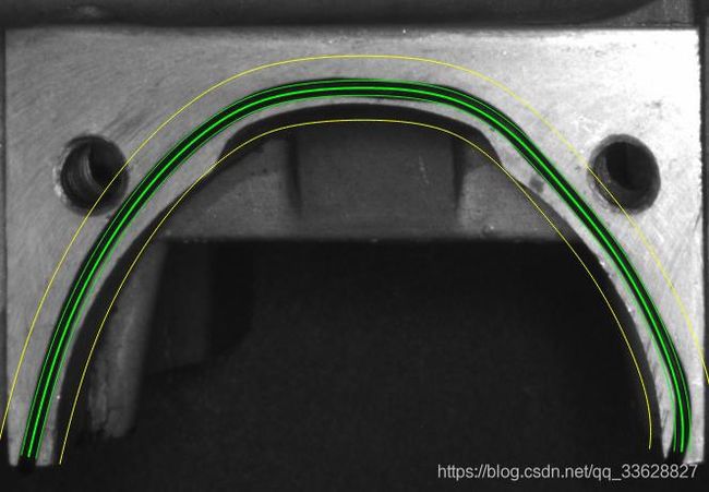
gen_parallel_contour_xld (ContourRef, ModelSide1, 'regression_normal', TargetWidth * 0.5)
gen_parallel_contour_xld (ContourRef, ModelSide2, 'regression_normal', -TargetWidth * 0.5)
concat_obj (ModelSide1, ModelSide2, ModelSides)
*
* Create two parallel contours to give an impression of where
* a correct adhesive bead should be located
*根据上面定义的点胶路径,生成两个与点胶路径平行的XLD,用来指示位置的范围,纯粹是为了显示更直观
gen_parallel_contour_xld (ContourRef, PositionToleranceSide1, 'regression_normal', PositionTolerance)
gen_parallel_contour_xld (ContourRef, PositionToleranceSide2, 'regression_normal', -PositionTolerance)
concat_obj (PositionToleranceSide1, PositionToleranceSide2, PositionToleranceSides)
dev_close_window ()
dev_open_window_fit_size (0, 0, PartColumn2 - PartColumn1 + 1, PartRow2 - PartRow1 + 41, -1, -1, WindowHandle)
set_display_font (WindowHandle, 16, 'mono', 'true', 'false')
dev_set_part (PartRow1 - 20, PartColumn1, PartRow2 + 20, PartColumn2)
dev_display (ImageAligned)
dev_set_line_width (2)
dev_set_color ('green')
dev_display (ContourRef)
dev_set_line_width (1)
dev_display (ModelSides)
dev_set_color ('yellow')
dev_display (PositionToleranceSides)
Message := 'Correct adhesive bead and the reference contour. The'
Message[1] := 'yellow contours indicate the range of position tolerance.'
dev_disp_text (Message, 'window', 12, 12, 'black', [], [])
dev_disp_text ('Press Run (F5) to continue', 'window', 'bottom', 'right', 'black', [], [])
stop ()
*
*
* Now, perform the inspection task
*以上定义好了标准的点胶路径与胶路宽度范围与胶路位置范围,下面读取出图片进行检测
TextOffset := 20
NumImages := 7
for Index := 1 to NumImages by 1
    read_image (Image, 'bead/adhesive_bead_' + Index$'02')
    *
    * Align the input image with the reference image
    *align_bead (Image, ImageAligned, ModelID, RowT, ColumnT)
    *先找出点胶位置的铁块在哪里把之转换到参考图像指示的点胶位置处
    find_planar_uncalib_deformable_model (Image, ModelID, -0.39, 0.78, 1, 1, 1, 1, 0.4, 1, 1, 5, 0.9, [], [], HomMat2D1, Score)
    hom_mat2d_invert (HomMat2D1, HomMat2DInvert)
    hom_mat2d_translate (HomMat2DInvert, RowT, ColumnT, HomMat2DTranslate)
    projective_trans_image (Image, ImageAligned, HomMat2DTranslate, 'bilinear', 'false', 'false')
    *
    * Apply the bead inspection model to the aligned image
    *把图像转换到标准点胶路径位置后对图像进行胶路检测,检测到左轮廓和右轮廓,如果胶路有误,指示出错误类型
    apply_bead_inspection_model (ImageAligned, LeftContour, RightContour, ErrorSegment, BeadInspectionModel, ErrorType)
    *
    * Display the segmented adhesive bead with its error segments
    set_window_param (WindowHandle, 'flush', 'false')
    dev_clear_window ()
    dev_display (ImageAligned)
    dev_set_line_width (1)
    dev_set_color ('white')
    dev_display (ContourRef)
    dev_display (ModelSides)
    dev_display (PositionToleranceSides)
    dev_set_line_width (2)
    dev_set_color ('green')
    dev_display (LeftContour)
    dev_display (RightContour)
    dev_set_color ('red')
    dev_display (ErrorSegment)
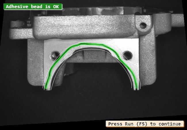
    *检测到胶路正常没有错误
    if (|ErrorType| == 0)
        * No errors detected
        Message := 'Adhesive bead is OK'
        dev_disp_text (Message, 'window', 12, 12, 'white', 'box_color', 'forest green')
        dev_disp_text ('Press Run (F5) to continue', 'window', 'bottom', 'right', 'black', [], [])
        flush_buffer (WindowHandle)
        set_window_param (WindowHandle, 'flush', 'true')
        stop ()
    *检测到胶路异常
    else
        * Display errors by error class
        *以下代码是显示出一些错误信息
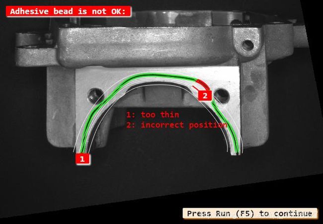
        Message[0] := 'Adhesive bead is not OK:'
        *
        ErrorClasses := ['no bead','too thin','too thick','incorrect position']
        for ClassIndex := 0 to |ErrorClasses| - 1 by 1
            Class := ErrorClasses[ClassIndex]
            ErrorIndices := find(ErrorType,Class)
            if (ErrorIndices != -1)
                select_obj (ErrorSegment, SelectedSegments, ErrorIndices + 1)
                dev_set_color ('red')
                dev_set_line_width (3)
                if (Class != 'no bead')
                    *生成错误区段
                    gen_display_segments (SelectedSegments, LeftContour, RightContour, ErrorParts)
                    dev_display (ErrorParts)
                else
                    dev_display (SelectedSegments)
                endif
                area_center_points_xld (SelectedSegments, Area, Row, Column)
                for E := 0 to |ErrorIndices| - 1 by 1
                    dev_disp_text (ErrorIndices[E] + 1, 'image', Row[E], Column[E] - TextOffset, 'white', 'box_color', 'red')
                    TextOffset := 20 - TextOffset
                endfor
            endif
        endfor
        dev_disp_text (Message, 'window', 12, 12, 'white', 'box_color', 'red')
        dev_disp_text ([1:|ErrorType|] + ': ' + ErrorType, 'image', 500, 500, 'red', 'box', 'false')
        if (Index < NumImages)
            dev_disp_text ('Press Run (F5) to continue', 'window', 'bottom', 'right', 'black', [], [])
            flush_buffer (WindowHandle)
            set_window_param (WindowHandle, 'flush', 'true')
            stop ()
        endif
    endif
endfor
flush_buffer (WindowHandle)
set_window_param (WindowHandle, 'flush', 'true')
*
* Release all allocated memory
clear_bead_inspection_model (BeadInspectionModel)
clear_deformable_model (ModelID)
以上例程加入了过多图像预处理的干扰信息,实际上胶路检测只需要定义标准胶宽,胶宽范围,胶路位置范围,生成胶路路径。
然后用create_bead_inspection_model 创建检测模型
读取检测图像后用apply_bead_inspection_model 检测胶路即可得到胶路的完整性信息
点胶模板图片:
点胶质量检测图片:


