System Extract 步骤
纲要:
把Composition下的SWC分配到System Description 描述的CAN网络的的ECU上。
 System Extract
目录
1. Create System Extract
2. Map SWC to ECU instance
3. Maping System Signal to Data Element
4. Create System Extract
1. Create System Extract
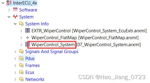
Right click on the project, create "System Info - Elements | System", which will create "07_WiperControl_System.arxml" file.
Configure the category as “SYSTEM_EXTRACT in "Property" Tab. [1]

2. Map SWC to ECU instance
Mapping Components under the "Composition" to ECUs under the "System Description":
2.1 Right click on the "07_WiperControl_System.arxml" file, open with "SwcToEcuMapping" editor. [2]
2.2 In this "07_WiperControl_System.arxml" file, configure the Top Level Composition to the “WiperControl_Composition”, which then will show all the available components under the composition. ("SwcToEcuMapping" editor 以 WiperControl_System这个Composition为基础显示)[3]
2.3 Create a "System Mapping", which will show all the EUCs belongs to the "System Description". Then you can assign the components to specific ECU as required. [4]
 SwcToEcuMapping
3. Maping System Signal to Data Element
Mapping "System Signal" in System Description to "Data Element" under Compositon.
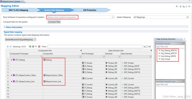
3.1 Right click on the "07_WiperControl_System.arxml" file, open with "SystemDataMapping" editor.
All the "SWC - Data Element" under the "Compositon" and all "System Signal" under the "System Decription" will show up. ("SystemDataMapping" editor 以 WiperControl_System这个Composition为基础显示)[5][6]
 SystemDataMapping Editor
3.2 Drag and drop the "System Signal" to the DataElement to map.[7]
4. Create System Extract
Right click on the "07_WiperControl_System.arxml" file, select "create System Extract". [8]
注:
[1] 除了“SYSTEM_EXTRACT”,还有ECU_EXTRACT等别的选项,通过这儿可以去判断这个arxml文件是System Extract还是别的
[2] 针对“System Extract” arxml 文件,除了“SwcToEcuMapping”,还有“SystemDataMapping” Editor 这个界面
[3] 所以本质上是按照Composition来分配SWC给ECU的,这也就是为什么project先去创建SWC和Composition,然后才去Import DBC去生成System Description
[4] Composition出SWC,DBC出ECU
[5] “SystemDataMapping” Editor 里面显示的是System Signal,而不是ISignal(ComSignal)
[6] 之所以在ISignal以上抽象出一个System Signal,是因为 ISignal 是跟CAN,LIN这些通讯协议绑定的,而用System Signal而不是ISignal与RTE上面的Data Element相连,就可以实现一个Data Element同时发送给不同的通讯协议,或者同时发给CAN协议下的多个子网络上
[7] 一部分 Data Element 已经在Composition那一步用 Assembly Connector与Composition内部的其他Data Element 相互连好了(Intra-ECU communication), 所以在“SystemDataMapping” 只需要把剩下的,那些需要和外部联系的Data Element 和System Signal给Mapping上即可(Inter-ECU communication through COM stack)
[8] output 是什么?
问:
1. “SystemDataMapping” Editor的界面上Data Element只有一个,如何实现将一个Data Element分别发送到不同的Network下的Signal上?
通过System Signal实现。首先在“SystemDataMapping”将Data Element给Mapping到一个System Signal上,然后在COM模块里面将该System Signal分别assign给不同的ComSignal(ISignal)即可实现
即System Signal 和 ISignal 的数量是不一致的,System Signal 总是小于或等于 ISignal
2. System Extract 和 ECU Extract 有什么区别,看起来System Extract有ECU Extract里面的所有内容,为什么还需要增加ECU Extract这一步?
“07_WiperControl_System.arxml” 这个System Extract文件里面就两大块内容,SwcToEcuMapping 和 SystemSignalMapping。
“WiperControl_System_EcuExtr.arxml” 这个ECU Extract文件也一样,就是SwcToEcuMapping 和 SystemSignalMapping。
之所以分两块,感觉上是因为System Extract arxml文件虽然是针对一个Composition的部署,但是它的SWC可能会部署到好几个ECU上。而ECU Extract arxml仅存储某一个ECU的信息,因为AUTOSAR project最终只会在一个ECU上运行。