Arduino UNO驱动 Si3531A三通道时钟信号发生器
Arduino UNO驱动 Si3531A三通道时钟信号发生器
-
- Si3531A模块简介
- 模块引脚定义
- Arduino UNO与模块接线
- 测试代码
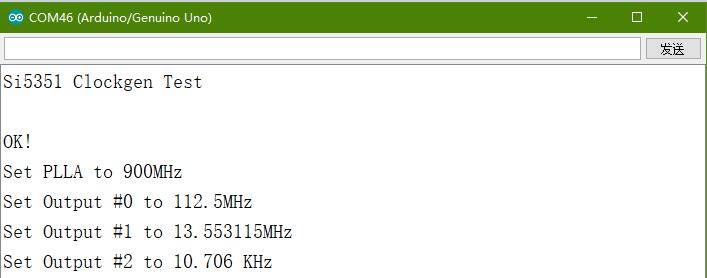
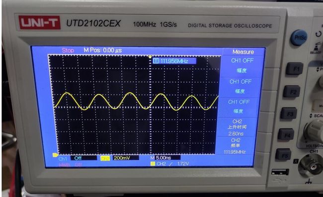
- 实验结果
Si3531A模块简介
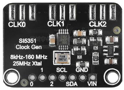
Si3531A是一个IIC接口可编程时钟信号频率发生器,能够替代晶振、晶体振荡器、压控振荡器、锁相环。基于PLL/VCXO+分频器结构。可在每个输出口产生8KHz-150MHz之间的频率信号。
输出阻抗:50Ω
输出占空比:50%
IIC通信速率:100Kbps-400Kbps
IIC器件地址:0x60
模块引脚定义
SCL:IIC接口时钟信号线;SDA:IIC接口数据信号线;VIN:3.3-5V电源正极;GND:电源负极
0/CLK0:通道0信号输出 1/CLK1:通道1信号输出 2/CLK2:通道2信号输出
Arduino UNO与模块接线
| Arduino UNO | Si5351 |
|---|---|
| A4 | SDA |
| A5 | SCL |
| VCC | VCC |
| GND | GND |
测试代码
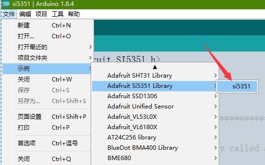
在Arduino IDE库管理器搜索Si5351,并安装如图示所例程库

#include <Adafruit_SI5351.h>

Adafruit_SI5351 clockgen = Adafruit_SI5351();

/**************************************************************************/
/*
    Arduino setup function (automatically called at startup)
*/
/**************************************************************************/
void setup(void)
{
  Serial.begin(9600);
  Serial.println("Si5351 Clockgen Test"); Serial.println("");

  /* Initialise the sensor */
  if (clockgen.begin() != ERROR_NONE)
  {
    /* There was a problem detecting the IC ... check your connections */
    Serial.print("Ooops, no Si5351 detected ... Check your wiring or I2C ADDR!");
    while(1);
  }

  Serial.println("OK!");

  /* INTEGER ONLY MODE --> most accurate output */
  /* Setup PLLA to integer only mode @ 900MHz (must be 600..900MHz) */
  /* Set Multisynth 0 to 112.5MHz using integer only mode (div by 4/6/8) */
  /* 25MHz * 36 = 900 MHz, then 900 MHz / 8 = 112.5 MHz */
  Serial.println("Set PLLA to 900MHz");
  clockgen.setupPLLInt(SI5351_PLL_A, 36);
  Serial.println("Set Output #0 to 112.5MHz");
  clockgen.setupMultisynthInt(0, SI5351_PLL_A, SI5351_MULTISYNTH_DIV_8);

  /* FRACTIONAL MODE --> More flexible but introduce clock jitter */
  /* Setup PLLB to fractional mode @616.66667MHz (XTAL * 24 + 2/3) */
  /* Setup Multisynth 1 to 13.55311MHz (PLLB/45.5) */
  clockgen.setupPLL(SI5351_PLL_B, 24, 2, 3);
  Serial.println("Set Output #1 to 13.553115MHz");
  clockgen.setupMultisynth(1, SI5351_PLL_B, 45, 1, 2);

  /* Multisynth 2 is not yet used and won't be enabled, but can be */
  /* Use PLLB @ 616.66667MHz, then divide by 900 -> 685.185 KHz */
  /* then divide by 64 for 10.706 KHz */
  /* configured using either PLL in either integer or fractional mode */

  Serial.println("Set Output #2 to 10.706 KHz");
  clockgen.setupMultisynth(2, SI5351_PLL_B, 900, 0, 1);
  clockgen.setupRdiv(2, SI5351_R_DIV_64);

  /* Enable the clocks */
  clockgen.enableOutputs(true);
}

/**************************************************************************/
/*
    Arduino loop function, called once 'setup' is complete (your own code
    should go here)
*/
/**************************************************************************/
void loop(void)
{
}
程序部分说明
1、设置PPL锁相环倍频器:三通道或两通道输出共用PLL_A或PLL_B。
设置PLL为整数模式,clockgen.setupPLLInt(SI5351_PLL_A or SI5351_PLL_B, m); 此函数将PLL_A或PLL_B设置成 25MHz * m频率值,m为整数取值范围15-90。
设置PLL为小数模式,clockgen.setupPLLInt(SI5351_PLL_A or SI5351_PLL_B, m, n, d); 此函数将PLL_A或PLL_B设置成 225MHz * (m + n/d)频率值,m为整数取值范围15-90,n取值范围0-1048575,d取值范围1-1048575。
PLL小数模式会有轻微的频率抖动,所以尽量用整数模式。
2、设置每一路输出的分频器
整数频率输出clockgen.setupMultisynthInt(output, SI5351_PLL_x, SI5351_MULTISYNTH_DIV_x); output取值0、1、2选择输出通道,SI5351_PLL_x取值倍频后的SI5351_PLL_A 或 SI5351_PLL_B,
SI5351_MULTISYNTH_DIV_x分频因子取值SI5351_MULTISYNTH_DIV_4, SI5351_MULTISYNTH_DIV_6, or SI5351_MULTISYNTH_DIV_8
小数频率输出clockgen.setupMultisynth(output, SI5351_PLL_x, div, n, d); output取值0、1、2选择输出通道,SI5351_PLL_x取值倍频后的SI5351_PLL_A 或 SI5351_PLL_B,div取值4-900,n取值0-1048575,d取值1-1048575。
3、附加R分频器固定频率值输出
clockgen.setupRdiv(output, SI5351_R_DIV_x); SI5351_R_DIV_x取值
SI5351_R_DIV_1
SI5351_R_DIV_2
SI5351_R_DIV_4
SI5351_R_DIV_8
SI5351_R_DIV_16
SI5351_R_DIV_32
SI5351_R_DIV_64
SI5351_R_DIV_128
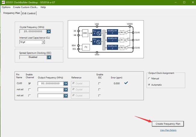
通过ClockBuilder软件计算出倍频分频因子得到所要产生的频率值
