Android多种方式实现相机圆形预览 看这一篇就够了,吐血整理
-
-
Typically you will set your viewport here. If your camera
-
is fixed then you could also set your projection matrix here:
-
void onSurfaceChanged(GL10 gl, int width, int height) {
-
gl.glViewport(0, 0, width, height); -
// for a fixed camera, set the projection too -
float ratio = (float) width / height; -
gl.glMatrixMode(GL10.GL_PROJECTION); -
gl.glLoadIdentity(); -
gl.glFrustumf(-ratio, ratio, -1, 1, 1, 10); -
}
-
@param gl the GL interface. Use
instanceofto -
test if the interface supports GL11 or higher interfaces.
-
@param width
-
@param height
*/
void onSurfaceChanged(GL10 gl, int width, int height);
/**
-
Called to draw the current frame.
-
-
This method is responsible for drawing the current frame.
-
-
The implementation of this method typically looks like this:
-
void onDrawFrame(GL10 gl) {
-
gl.glClear(GL10.GL_COLOR_BUFFER_BIT | GL10.GL_DEPTH_BUFFER_BIT); -
//... other gl calls to render the scene ... -
}
-
@param gl the GL interface. Use
instanceofto -
test if the interface supports GL11 or higher interfaces.
*/
void onDrawFrame(GL10 gl);
}
void onSurfaceCreated(GL10 gl, EGLConfig config)
在Surface创建或重建的情况下回调
void onSurfaceChanged(GL10 gl, int width, int height)
在Surface的大小发生变化的情况下回调
void onDrawFrame(GL10 gl)
在这里实现绘制操作。当我们设置的renderMode为RENDERMODE_CONTINUOUSLY时,该函数将不断地执行;
当我们设置的renderMode为RENDERMODE_WHEN_DIRTY时,将只在创建完成和调用requestRender后才执行。一般我们选择RENDERMODE_WHEN_DIRTY渲染模式,避免过度绘制。
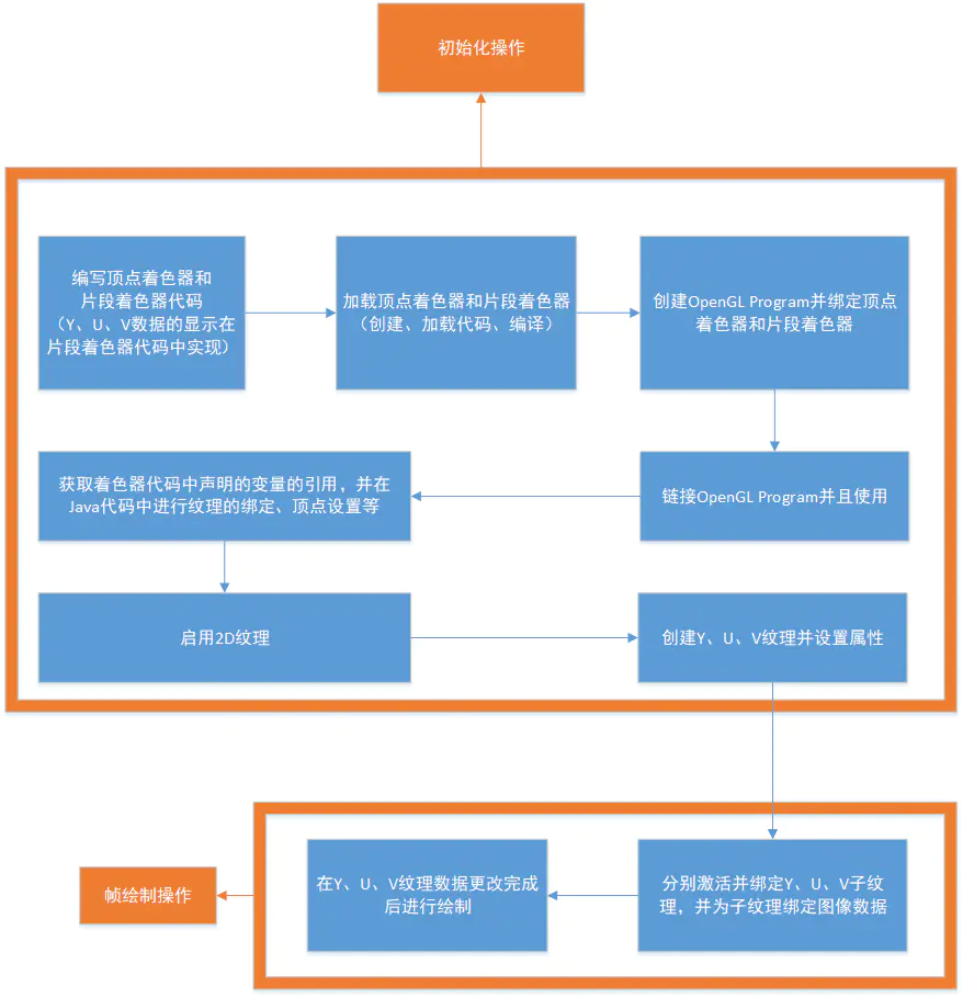
一般情况下,我们会自己实现一个Renderer,然后为GLSurfaceView设置Renderer,可以说,Renderer的编写是整个流程的核心步骤。以下是在void onSurfaceCreated(GL10 gl, EGLConfig config)进行的初始化操作和在void onDrawFrame(GL10 gl)进行的绘制操作的流程图:
2. 具体实现
- 坐标系介绍
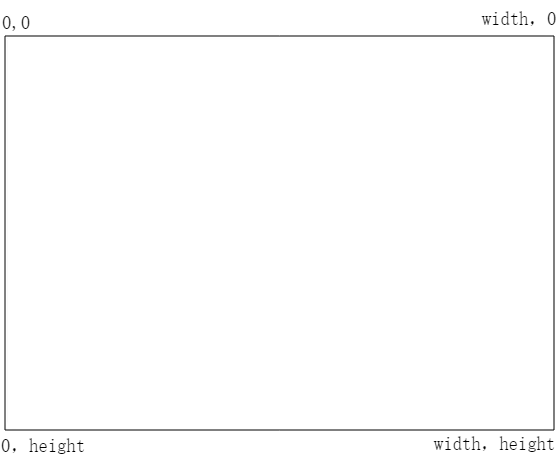
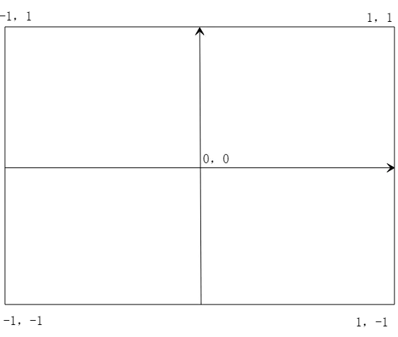
如图所示,和Android的View坐标系不同,OpenGL的坐标系是笛卡尔坐标系。
Android View的坐标系以左上角为原点,向右x递增,向下y递增;
而OpenGL坐标系以中心为原点,向右x递增,向上y递增。
- 着色器编写
/**
- 顶点着色器
*/
private static String VERTEX_SHADER =
" attribute vec4 attr_position;\n" +
" attribute vec2 attr_tc;\n" +
" varying vec2 tc;\n" +
" void main() {\n" +
" gl_Position = attr_position;\n" +
" tc = attr_tc;\n" +
" }";
/**
- 片段着色器
*/
private static String FRAG_SHADER =
" varying vec2 tc;\n" +
" uniform sampler2D ySampler;\n" +
" uniform sampler2D uSampler;\n" +
" uniform sampler2D vSampler;\n" +
" const mat3 convertMat = mat3( 1.0, 1.0, 1.0, -0.001, -0.3441, 1.772, 1.402, -0.7141, -0.58060);\n" +
" void main()\n" +
" {\n" +
" vec3 yuv;\n" +
" yuv.x = texture2D(ySampler, tc).r;\n" +
" yuv.y = texture2D(uSampler, tc).r - 0.5;\n" +
" yuv.z = texture2D(vSampler, tc).r - 0.5;\n" +
" gl_FragColor = vec4(convertMat * yuv, 1.0);\n" +
" }";
-
内建变量解释
-
gl_Position
VERTEX_SHADER代码里的gl_Position代表绘制的空间坐标。由于我们是二维绘制,所以直接传入OpenGL二维坐标系的左下(-1,-1)、右下(1,-1)、左上(-1,1)、右上(1,1),也就是{-1,-1,1,-1,-1,1,1,1}
gl_FragColor
FRAG_SHADER代码里的gl_FragColor代表单个片元的颜色
-
其他变量解释
-
ySampler、uSampler、vSampler
分别代表Y、U、V纹理采样器
convertMat
根据以下公式:
R = Y + 1.402 (V - 128)
G = Y - 0.34414 (U - 128) - 0.71414 (V - 128)
B = Y + 1.772 (U - 128)
我们可得到一个YUV转RGB的矩阵
1.0, 1.0, 1.0,
0, -0.344, 1.77,
1.403, -0.714, 0
-
部分类型、函数的解释
-
vec3、vec4
分别代表三维向量、四维向量。
vec4 texture2D(sampler2D sampler, vec2 coord)
以指定的矩阵将采样器的图像纹理转换为颜色值;如:
texture2D(ySampler, tc).r获取到的是Y数据,
texture2D(uSampler, tc).r获取到的是U数据,
texture2D(vSampler, tc).r获取到的是V数据。
- 在Java代码中进行初始化
根据图像宽高创建Y、U、V对应的ByteBuffer纹理数据;
根据是否镜像显示、旋转角度选择对应的转换矩阵;
public void init(boolean isMirror, int rotateDegree, int frameWidth, int frameHeight) {
if (this.frameWidth == frameWidth
&& this.frameHeight == frameHeight
&& this.rotateDegree == rotateDegree
&& this.isMirror == isMirror) {
return;
}
dataInput = false;
this.frameWidth = frameWidth;
this.frameHeight = frameHeight;
this.rotateDegree = rotateDegree;
this.isMirror = isMirror;
yArray = new byte[this.frameWidth * this.frameHeight];
uArray = new byte[this.frameWidth * this.frameHeight / 4];
vArray = new byte[this.frameWidth * this.frameHeight / 4];
int yFrameSize = this.frameHeight * this.frameWidth;
int uvFrameSize = yFrameSize >> 2;
yBuf = ByteBuffer.allocateDirect(yFrameSize);
yBuf.order(ByteOrder.nativeOrder()).position(0);
uBuf = ByteBuffer.allocateDirect(uvFrameSize);
uBuf.order(ByteOrder.nativeOrder()).position(0);
vBuf = ByteBuffer.allocateDirect(uvFrameSize);
vBuf.order(ByteOrder.nativeOrder()).p
osition(0);
// 顶点坐标
squareVertices = ByteBuffer
.allocateDirect(GLUtil.SQUARE_VERTICES.length * FLOAT_SIZE_BYTES)
.order(ByteOrder.nativeOrder())
.asFloatBuffer();
squareVertices.put(GLUtil.SQUARE_VERTICES).position(0);
//纹理坐标
if (isMirror) {
switch (rotateDegree) {
case 0:
coordVertice = GLUtil.MIRROR_COORD_VERTICES;
break;
case 90:
coordVertice = GLUtil.ROTATE_90_MIRROR_COORD_VERTICES;
break;
case 180:
coordVertice = GLUtil.ROTATE_180_MIRROR_COORD_VERTICES;
break;
case 270:
coordVertice = GLUtil.ROTATE_270_MIRROR_COORD_VERTICES;
break;
default:
break;
}
} else {
switch (rotateDegree) {
case 0:
coordVertice = GLUtil.COORD_VERTICES;
break;
case 90:
coordVertice = GLUtil.ROTATE_90_COORD_VERTICES;
break;
case 180:
coordVertice = GLUtil.ROTATE_180_COORD_VERTICES;
break;
case 270:
coordVertice = GLUtil.ROTATE_270_COORD_VERTICES;
break;
default:
break;
}
}
coordVertices = ByteBuffer.allocateDirect(coordVertice.length * FLOAT_SIZE_BYTES).order(ByteOrder.nativeOrder()).asFloatBuffer();
coordVertices.put(coordVertice).position(0);
}
在Surface创建完成时进行Renderer初始化
private void initRenderer() {
rendererReady = false;
createGLProgram();
//启用纹理
GLES20.glEnable(GLES20.GL_TEXTURE_2D);
//创建纹理
createTexture(frameWidth, frameHeight, GLES20.GL_LUMINANCE, yTexture);
createTexture(frameWidth / 2, frameHeight / 2, GLES20.GL_LUMINANCE, uTexture);
createTexture(frameWidth / 2, frameHeight / 2, GLES20.GL_LUMINANCE, vTexture);
rendererReady = true;
}
其中createGLProgram用于创建OpenGL Program并关联着色器代码中的变量
private void createGLProgram() {
int programHandleMain = GLUtil.createShaderProgram();
if (programHandleMain != -1) {
// 使用着色器程序
GLES20.glUseProgram(programHandleMain);
// 获取顶点着色器变量
int glPosition = GLES20.glGetAttribLocation(programHandleMain, “attr_position”);
int textureCoord = GLES20.glGetAttribLocation(programHandleMain, “attr_tc”);
// 获取片段着色器变量
int ySampler = GLES20.glGetUniformLocation(programHandleMain, “ySampler”);
int uSampler = GLES20.glGetUniformLocation(programHandleMain, “uSampler”);
int vSampler = GLES20.glGetUniformLocation(programHandleMain, “vSampler”);
//给变量赋值
/**
-
GLES20.GL_TEXTURE0 和 ySampler 绑定
-
GLES20.GL_TEXTURE1 和 uSampler 绑定
-
GLES20.GL_TEXTURE2 和 vSampler 绑定
-
也就是说 glUniform1i的第二个参数代表图层序号
*/
GLES20.glUniform1i(ySampler, 0);
GLES20.glUniform1i(uSampler, 1);
GLES20.glUniform1i(vSampler, 2);
GLES20.glEnableVertexAttribArray(glPosition);
GLES20.glEnableVertexAttribArray(textureCoord);
/**
- 设置Vertex Shader数据
*/
squareVertices.position(0);
GLES20.glVertexAttribPointer(glPosition, GLUtil.COUNT_PER_SQUARE_VERTICE, GLES20.GL_FLOAT, false, 8, squareVertices);
coordVertices.position(0);
GLES20.glVertexAttribPointer(textureCoord, GLUtil.COUNT_PER_COORD_VERTICES, GLES20.GL_FLOAT, false, 8, coordVertices);
}
}
其中createTexture用于根据宽高和格式创建纹理
private void createTexture(int width, int height, int format, int[] textureId) {
//创建纹理
GLES20.glGenTextures(1, textureId, 0);
//绑定纹理
GLES20.glBindTexture(GLES20.GL_TEXTURE_2D, textureId[0]);
/**
-
{@link GLES20#GL_TEXTURE_WRAP_S}代表左右方向的纹理环绕模式
-
{@link GLES20#GL_TEXTURE_WRAP_T}代表上下方向的纹理环绕模式
-
{@link GLES20#GL_REPEAT}:重复
-
{@link GLES20#GL_MIRRORED_REPEAT}:镜像重复
-
{@link GLES20#GL_CLAMP_TO_EDGE}:忽略边框截取
-
例如我们使用{@link GLES20#GL_REPEAT}:
-
squareVertices coordVertices -
-1.0f, -1.0f, 1.0f, 1.0f, -
1.0f, -1.0f, 1.0f, 0.0f, -> 和textureView预览相同 -
-1.0f, 1.0f, 0.0f, 1.0f, -
1.0f, 1.0f 0.0f, 0.0f -
squareVertices coordVertices -
-1.0f, -1.0f, 2.0f, 2.0f, -
1.0f, -1.0f, 2.0f, 0.0f, -> 和textureView预览相比,分割成了4 块相同的预览(左下,右下,左上,右上) -
-1.0f, 1.0f, 0.0f, 2.0f, -
1.0f, 1.0f 0.0f, 0.0f
*/
GLES20.glTexParameteri(GLES20.GL_TEXTURE_2D, GLES20.GL_TEXTURE_WRAP_S, GLES20.GL_REPEAT);
GLES20.glTexParameteri(GLES20.GL_TEXTURE_2D, GLES20.GL_TEXTURE_WRAP_T, GLES20.GL_REPEAT);
/**
-
{@link GLES20#GL_TEXTURE_MIN_FILTER}代表所显示的纹理比加载进来的纹理小时的情况
-
{@link GLES20#GL_TEXTURE_MAG_FILTER}代表所显示的纹理比加载进来的纹理大时的情况
-
{@link GLES20#GL_NEAREST}:使用纹理中坐标最接近的一个像素的颜色作为需要绘制的像素颜色
-
{@link GLES20#GL_LINEAR}:使用纹理中坐标最接近的若干个颜色,通过加权平均算法得到需要绘制的像素颜色
*/
GLES20.glTexParameteri(GLES20.GL_TEXTURE_2D, GLES20.GL_TEXTURE_MIN_FILTER, GLES20.GL_NEAREST);
GLES20.glTexParameteri(GLES20.GL_TEXTURE_2D, GLES20.GL_TEXTURE_MAG_FILTER, GLES20.GL_LINEAR);
GLES20.glTexImage2D(GLES20.GL_TEXTURE_2D, 0, format, width, height, 0, format, GLES20.GL_UNSIGNED_BYTE, null);
}
- 在Java代码中调用绘制
在数据源获取到时裁剪并传入帧数据
@Override
public void onPreview(final byte[] nv21, Camera camera) {
//裁剪指定的图像区域
ImageUtil.cropNV21(nv21, this.squareNV21, previewSize.width, previewSize.height, cropRect);
//刷新GLSurfaceView
roundCameraGLSurfaceView.refreshFrameNV21(this.squareNV21);
}
NV21数据裁剪代码
/**
-
裁剪NV21数据
-
@param originNV21 原始的NV21数据
-
@param cropNV21 裁剪结果NV21数据,需要预先分配内存
-
@param width 原始数据的宽度
-
@param height 原始数据的高度
-
@param left 原始数据被裁剪的区域的左边界
-
@param top 原始数据被裁剪的区域的上边界
-
@param right 原始数据被裁剪的区域的右边界
-
@param bottom 原始数据被裁剪的区域的下边界
*/
public static void cropNV21(byte[] originNV21, byte[] cropNV21, int width, int height, int left, int top, int right, int bottom) {
int halfWidth = width / 2;
int cropImageWidth = right - left;
int cropImageHeight = bottom - top;
//原数据Y左上
int originalYLineStart = top * width;
int targetYIndex = 0;
//原数据UV左上
int originalUVLineStart = width * height + top * halfWidth;
//目标数据的UV起始值
int targetUVIndex = cropImageWidth * cropImageHeight;
for (int i = top; i < bottom; i++) {
System.arraycopy(originNV21, originalYLineStart + left, cropNV21, targetYIndex, cropImageWidth);
originalYLineStart += width;
targetYIndex += cropImageWidth;
if ((i & 1) == 0) {
System.arraycopy(originNV21, originalUVLineStart + left, cropNV21, targetUVIndex, cropImageWidth);
originalUVLineStart += width;
targetUVIndex += cropImageWidth;
}
}
}
传给GLSurafceView并刷新帧数据
/**
-
传入NV21刷新帧
-
@param data NV21数据
*/
public void refreshFrameNV21(byte[] data) {
if (rendererReady) {
yBuf.clear();
uBuf.clear();
vBuf.clear();
putNV21(data, frameWidth, frameHeight);
dataInput = true;
requestRender();
}
}
其中putNV21用于将NV21中的Y、U、V数据分别取出
/**
-
将NV21数据的Y、U、V分量取出
-
@param src nv21帧数据
-
@param width 宽度
-
@param height 高度
*/
private void putNV21(byte[] src, int width, int height) {
int ySize = width * height;
int frameSize = ySize * 3 / 2;
//取分量y值
System.arraycopy(src, 0, yArray, 0, ySize);
int k = 0;
//取分量uv值
int index = ySize;
while (index < frameSize) {
vArray[k] = src[index++];
uArray[k++] = src[index++];
}
yBuf.put(yArray).position(0);
uBuf.put(uArray).position(0);
vBuf.put(vArray).position(0);
}
在执行requestRender后,onDrawFrame函数将被回调,在其中进行三个纹理的数据绑定并绘制
@Override
public void onDrawFrame(GL10 gl) {
// 分别对每个纹理做激活、绑定、设置数据操作
if (dataInput) {
//y
GLES20.glActiveTexture(GLES20.GL_TEXTURE0);
GLES20.glBindTexture(GLES20.GL_TEXTURE_2D, yTexture[0]);
GLES20.glTexSubImage2D(GLES20.GL_TEXTURE_2D,
0,
0,
0,
frameWidth,
frameHeight,
GLES20.GL_LUMINANCE,
GLES20.GL_UNSIGNED_BYTE,
yBuf);
//u
GLES20.glActiveTexture(GLES20.GL_TEXTURE1);
GLES20.glBindTexture(GLES20.GL_TEXTURE_2D, uTexture[0]);
GLES20.glTexSubImage2D(GLES20.GL_TEXTURE_2D,
0,
0,
0,
frameWidth >> 1,
frameHeight >> 1,
GLES20.GL_LUMINANCE,
GLES20.GL_UNSIGNED_BYTE,
uBuf);
//v
GLES20.glActiveTexture(GLES20.GL_TEXTURE2);
GLES20.glBindTexture(GLES20.GL_TEXTURE_2D, vTexture[0]);
GLES20.glTexSubImage2D(GLES20.GL_TEXTURE_2D,
0,
0,
0,
ion(0);
}
在执行requestRender后,onDrawFrame函数将被回调,在其中进行三个纹理的数据绑定并绘制
@Override
public void onDrawFrame(GL10 gl) {
// 分别对每个纹理做激活、绑定、设置数据操作
if (dataInput) {
//y
GLES20.glActiveTexture(GLES20.GL_TEXTURE0);
GLES20.glBindTexture(GLES20.GL_TEXTURE_2D, yTexture[0]);
GLES20.glTexSubImage2D(GLES20.GL_TEXTURE_2D,
0,
0,
0,
frameWidth,
frameHeight,
GLES20.GL_LUMINANCE,
GLES20.GL_UNSIGNED_BYTE,
yBuf);
//u
GLES20.glActiveTexture(GLES20.GL_TEXTURE1);
GLES20.glBindTexture(GLES20.GL_TEXTURE_2D, uTexture[0]);
GLES20.glTexSubImage2D(GLES20.GL_TEXTURE_2D,
0,
0,
0,
frameWidth >> 1,
frameHeight >> 1,
GLES20.GL_LUMINANCE,
GLES20.GL_UNSIGNED_BYTE,
uBuf);
//v
GLES20.glActiveTexture(GLES20.GL_TEXTURE2);
GLES20.glBindTexture(GLES20.GL_TEXTURE_2D, vTexture[0]);
GLES20.glTexSubImage2D(GLES20.GL_TEXTURE_2D,
0,
0,
0,


