串行/解串器的设计
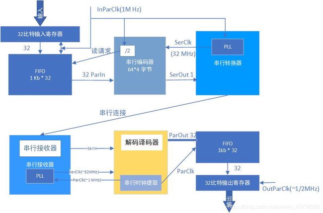
PCIe总线是用来取代PCI总线的新型串行总线协议。这个与将要设计的串行解串器类似。对于利用串行解串器来进行数据传输的两个系统,要发送的数据会先被保存下来,然后被送入到一个缓冲区内(即FIFO),接着,它们被串行化,然后一个一个比特地被发送给目标系统。在接收端,输入的串行数据被解串,然后再次保存到缓冲区内,并按照并行的格式被发送到接收系统的并行总线上,为了实现数据的同步,接收端必须从接收的串行数据中提取出数据的有效时钟信息。这里的时钟其实和接收数据的帧边界其实是同一个概念,整个串行/解串器的结构如图所示:
先从时钟源设计开始:
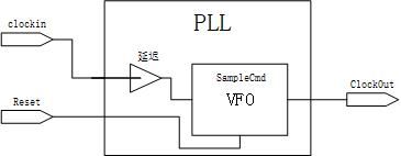
一个典型的锁相环(PLL)由以下三部分构成:输出时钟产生器,可变频率振荡器(VFO)。PLL会比较输入时钟相位和VFO时钟的差别,并根据这个差别来调整VFO产生的时钟的频率,其原理图如下:
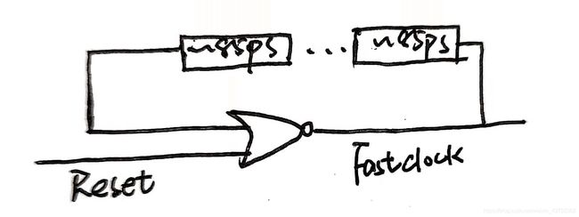
我们用目标库中速度最快的延迟单元来完成 这个可以工作很高时钟下的振荡器的设计,在verilog方面主要体现在以下两方面:1.用generate来表示线延迟;2.添加DC的set_dont_touch来阻止综合工具把我们认为增加的线延迟给优化掉;
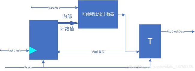
把这个振荡器命名为FsatClock,并作为时钟驱动计数器,把计数器的门限值VaryFreq,用来控制VFO的时钟频率。
VFO的内部的比较器将计数值与计数器的溢出门限值VaryFreq相比较,当计数值达到门限值,计数器被复位。
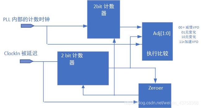
以上我们可以得到一个32x的PLL,32xPLL受到1MHz的时钟驱动,并且采样VFO的PLL输出。设置两个计数器,一个是被外部的PLL1MHz的输入时钟驱动,另一个是被PLL内部的P1MHZ的溢出计数器产生的时钟驱动,每个时钟到来时把计数值进行比较,从而得到两个时钟的相对关系。只要两个计数值不相等就会去调整VFO的频率。这两个2比特的计数器对32xPLL Muounter计数器产生时钟输出连续计数,在每一个PLL时钟的上升沿,对应边沿的计数值都用来做比较,从而产生乐调整VFO且及时更新的调整量。模块Zeroer不断检测ClockIn的计数值,当计数值为3时,计数器同时清零。
模块的代码如下:
1.Top
module PLLTop (output ClockOut, input ClockIn, Reset);
//
wire[1:0] AdjFreq;
wire MHz32, CtrCarry;
//
// -----------------------------------------------
// The new sample edge generator:
wire SampleWire;
//
DEL005 SampleDelay1 (.Z(SampleWire), .I(ClockIn));
//
//synopsys dc_tcl_script_begin
// set_dont_touch SampleDelay1
// set_dont_touch SampleWire
// set_dont_touch ClockIn
//synopsys dc_tcl_script_end
//
// -----------------------------------------------
assign ClockOut = MHz32;
//
ClockComparator
Comp1 ( .AdjustFreq(AdjFreq), .ClockIn(ClockIn)
      , .CounterClock(CtrCarry), .Reset(Reset)
      );
//
VFO
VFO1 ( .ClockOut(MHz32), .AdjustFreq(AdjFreq)
     , .Sample(SampleWire), .Reset(Reset)
     );
//
MultiCounter
MCntr1 (.CarryOut(CtrCarry), .Clock(MHz32), .Reset(Reset));
//
endmodule // PLLTop.
//
2.VFO
// The timescale and VFO_MaxDelta from the Deserializer
// design are used in VFO:
//
`include "SerDes.inc"
//
// ---------------------------------------------------
// The empirical frequency-setting parameters:
// DivideFactor is the number of fast-counter increments
// per PLL output clock.   Thus, PLL output period is
// given by: T = 2*DivideFactor*ElemDelay, in which,
//
// ElemDelay = DelayElementAvgDelay
//
// ElemDelay is estimated in ns, averaged over rise &
// fall, and it is used in VCS message calculations as
// well as VFO frequency limit stops.
//
// ---------------------------------------------------
// The next macro configures the FastClock oscillator and
// FastDivvy counter (2 elems probably is too fast for
// DEL005 and 90-nm Typical gates):
//
`define NumElems  5      // Delay line length.
//
// ---------------------------------------------------
// We use the PLL multiplication factor, 32, to set the
// initial DivideFactor.
// We want to divide the frequency, and the delay line
// just gives edge delays, so the initial divide factor
// should be about 1/4 the PLL multiplication factor:
//
`define ElemDelay 0.0850 // Delay element avg. delay.
`define DivideFactor 32.0/(4.0*`NumElems*`ElemDelay)
//
// NFastBits will be calculated to ensure that the
// frequency initialization value (`DivideFactor) will
// be less than the maximum value of the FastDivvy and
// DivideFactor regs declared below.
// ---------------------------------------------------
module VFO (output ClockOut, input[1:0] AdjustFreq
           , input Sample, Reset
           );
reg    ClockOutReg;
assign ClockOut = ClockOutReg;
//
// Configure the fast clock counter:
localparam NFastBits =
                     (`DivideFactor < (2**3 - (`VFO_MaxDelta/(2.0*`ElemDelay) + 1)) )? 3
                   : (`DivideFactor < (2**4 - (`VFO_MaxDelta/(2.0*`ElemDelay) + 1)) )? 4
                   : (`DivideFactor < (2**5 - (`VFO_MaxDelta/(2.0*`ElemDelay) + 1)) )? 5
                   : (`DivideFactor < (2**6 - (`VFO_MaxDelta/(2.0*`ElemDelay) + 1)) )? 6
                   : (`DivideFactor < (2**7 - (`VFO_MaxDelta/(2.0*`ElemDelay) + 1)) )? 7
                   : (`DivideFactor < (2**8 - (`VFO_MaxDelta/(2.0*`ElemDelay) + 1)) )? 8
                   : 9;
//
localparam[NFastBits-1:0] DivideLoLim = `DivideFactor - `VFO_MaxDelta;
localparam[NFastBits-1:0] DivideHiLim = `DivideFactor + `VFO_MaxDelta;
//
// Assertions:
`ifdef DC
`else
initial
  begin
  $display("VFO FastClock delay chain: %0.0f cells @%1.4f ns; f divider=[%0.0f] bits.\n"
          ,                          `NumElems, `ElemDelay,         NFastBits
          );
  $display("VFO divide factor=%0.0f; so, initial SYNTH 1 MHz in => %2.1f MHz out.\n"
          ,       `DivideFactor, 1000.0/32.0
          );
  $display("`VFO_MaxDelta=[%0.0f] => Divider limits: Low Lim=%0.0f and High Lim=%0.0f.\n"
          , `VFO_MaxDelta,                           DivideLoLim,          DivideHiLim
          );
  end
`endif
//
// ----------------------------------------------------------
// Generate the free-running clock (FastClock), using a chain
// of delay cells:
//
wire[`NumElems:0] WireD;
//
generate
  genvar i;
  for (i=0; i<`NumElems; i = i+1)
    begin : DelayLine
    DEL005 Delay85ps ( .Z(WireD[i+1]), .I(WireD[i]) );
    end
endgenerate
//
//synopsys dc_tcl_script_begin
// set_dont_touch DelayLine*
// set_dont_touch *Delay85ps*
// set_dont_touch WireD*
//synopsys dc_tcl_script_end
//
reg FastClock;
//
always@(Reset, WireD)
  begin : FastClockGen
  if (Reset==1'b1)
       FastClock = 1'b0;
  else // The free-running clock gets the output of the delay line:
       FastClock = WireD[`NumElems];
  end
//
// Feed the inverted edge back into the delay line
// and create the oscillator inverter:
assign WireD[0] = ~FastClock;
//
// ----------------------------------------------------------
// Define the adjustable output clock.  This is just a counter
// with a variable wrap to 0.   FastDivvy wraps to set the delay
// according to the required DivideFactor.
//
reg[NFastBits-1:0] FastDivvy, DivideFactor;
//
always@(posedge FastClock, posedge Reset)
  begin : ClockOutGen
  if (Reset==1'b1)
       begin
       FastDivvy   <=  'b0;
       ClockOutReg <= 1'b0;
       end
  else begin
       if (FastDivvy < DivideFactor)
            FastDivvy <= FastDivvy + 1'b1;
       else begin
            FastDivvy   <= 'b0;
            ClockOutReg <= ~ClockOutReg;
            end
       end
  end // ClockOutGen.
//
// ----------------------------------------------------------
// Use the PLL sampler to adjust the clock half-period.
//
always@(posedge Sample, posedge Reset)
  begin : Sampler
  if (Reset==1'b1)
       DivideFactor <= `DivideFactor;
  else begin
       case (AdjustFreq)
         2'b00: // Adjust f down (delay up):
                if (DivideFactor < DivideHiLim)
                   DivideFactor <= DivideFactor + 1'b1;
         2'b11: // Adjust f up (delay down):
                if (DivideFactor > DivideLoLim)
                   DivideFactor <= DivideFactor - 1'b1;
       endcase // Default: leave DivideFactor alone.
       end
  end // Sampler.
//
endmodule // VFO.
//
// Prevent local defines from getting to other
// compilation modules:
`undef ElemDelay
`undef NumElems
`undef DivideFactor
//
3.ClockCmp
module ClockComparator (output reg[1:0] AdjustFreq
                       , input ClockIn, CounterClock, Reset
                       );
reg[1:0] ClockInN, CounterClockN;
reg ZeroCounters;
//
always@(posedge ClockIn, posedge ZeroCounters)
  begin : ClockCtr
  if (ZeroCounters==1'b1)
       ClockInN <= 2'b00;
  else ClockInN <= ClockInN + 2'b01;
  end
//
always@(posedge CounterClock, posedge ZeroCounters)
  begin : CounterCtr
  if (ZeroCounters==1'b1)
       CounterClockN <= 2'b00;
  else CounterClockN <= CounterClockN + 2'b01;
  end
//
always@(posedge ClockIn, posedge Reset)
  begin : Zeroer
  if (Reset==1'b1)
       ZeroCounters <= 1'b1;
  else ZeroCounters <= (ClockInN==2'b11)? 1'b1 : 1'b0;
  end
//
// Clock with the sampled CounterClock so that
// ClockIn is set up for case statement:
//
always@(posedge CounterClock, posedge Reset)
  begin : EdgeComparator
  if (Reset==1'b1) AdjustFreq = 2'b01;
  else
  case (ClockInN)
    2'b00: begin
           case (CounterClockN)
             2'b00: AdjustFreq = 2'b01; // No change.
             2'b01: AdjustFreq = 2'b01; // No change.
             2'b10: AdjustFreq = 2'b00; // Slow the counter.
           default: AdjustFreq = 2'b00; // Slow the counter.
           endcase
           end
    2'b01: begin
           case (CounterClockN)
             2'b00: AdjustFreq = 2'b11; // Speed up the counter.
             2'b01: AdjustFreq = 2'b01; // No change.
             2'b10: AdjustFreq = 2'b00; // Slow the counter.
           default: AdjustFreq = 2'b00; // Slow the counter.
           endcase
           end
    2'b10: begin
           case (CounterClockN)
             2'b00: AdjustFreq = 2'b11; // Speed up the counter.
             2'b01: AdjustFreq = 2'b11; // Speed up the counter.
             2'b10: AdjustFreq = 2'b10; // No change.
           default: AdjustFreq = 2'b00; // Slow the counter.
           endcase
           end
  default: begin // Includes 2'b11; allows initialization:
           case (CounterClockN)
             2'b00: AdjustFreq = 2'b11; // Speed up the counter.
             2'b01: AdjustFreq = 2'b11; // Speed up the counter.
             2'b10: AdjustFreq = 2'b10; // No change.
           default: AdjustFreq = 2'b10; // No change.
           endcase
           end
  endcase
  end
//
endmodule // ClockComparator.
在Deserializer部分,包括FIFO缓冲器,串行解码器以及串行接收模块:
1.FIFO部分\
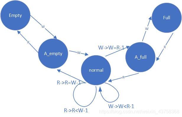
FIFO的状态转移如图所示:
FIFO由存储器和寄存器的控制模块构成。
存储器:
我们需要同时读写memory,所以需要两条总线,把读写逻辑分成两个always中去,其中Reader块要进行奇偶校验,因此,奇偶校验错误时,输出应该被复位成0. 而Write块需要初始化memory,即是给所有的地址都写.
module DPMem1kx32
   #(parameter AWid = 5  // Default length of RAM storage.
   ,           DWid = 32 // Default addressable word width.
   )
   ( output Dready          // Data valid during a read.
   , ParityErr              // Parity error on read.
   , output[DWid-1:0] DataO // For read from storage.
   , input[DWid-1:0]  DataI // For write to storage.
   , input[AWid-1:0]  AddrR // Read address.
   , input[AWid-1:0]  AddrW // Write address.
   , input ClkR             // Clocks data out.
   , input ClkW             // Clocks data in.
   , ChipEna       // Enables data output drivers.
   , Read          // Stored data are copied to Data[].
   , Write         // Data[] values replace stored values.
   , Reset         // Clears memory to allow parity checks.
   );
//
localparam MemHi = (1<
2.FIFO状态机
因为两套总线,两套时钟信号:除非只有一个时钟,否则状态机的状态时不确定的,所以需要利用这些输入来产生一个时钟。
always@(ClkR, ClkW)
  StateClockRaw = ~(ClkR && ClkW);
状态机必须保存状态,因此需要一个时钟作用下的时序逻辑状态转移模块,把我们之前的约束用于编码,要把非阻塞赋值和阻塞赋值分开,因此:
1.在一个小的时钟触发模块里使用非阻塞赋值语句实现状态转移,
2.FIFO的寄存器放在另外一个模块里面。
3.我们还需要两个时序元件:读计数器和写计数器
对于读写的计数器:我们需要实现当输入为1'b1时,地址就会增加的,当输入为1'b0时,地址就会停止的相关操作;
对于读指针来说,其跳转的always应该这么写:
// --------------------------------------------------------
// Read logic:
//
always@(posedge StateClock, posedge Reset)
  begin : IncrReadBlock
  if (Reset==1'b1)
       ReadAr <= 'b0;
  else begin
       if (CurState==emptyS)
            ReadAr <= 'b0;
       else if (ReadCmdr==1'b1)
              ReadAr <= ReadAr + 1;
       end
  end
//
通过控制IncrRead任务输入了,来控制ReadCmdr的输出,从而控制读指针的跳转;
如果FIFO是空的,照理说,往哪里写数据都是可以的,但是emptyS里的ReadAr的初始值我们可以不用去关心,但是我们希望计数器从一个确定的值开始增加。两个计数器从一个值同时增加
因此读任务可以这么写:
task incrRead(input ActionR);
  begin
  if (ActionR==1'b1)
       begin
       if (CurState==emptyS)
            begin
            ReadCmdr  = 1'b0;
            OldReadAr =  'b0;
            end
       else begin
            if (OldReadAr==ReadAr) // Schedule an incr.
                 ReadCmdr = 1'b1;
            else begin // No incr; already changed:
                 ReadCmdr  = 1'b0;
                 OldReadAr = ReadAr;
                 end
            end
       end
  else begin // ActionR is a reset:
       ReadCmdr  = 1'b0;
       OldReadAr =  'b0;
       end
  end
endtask
同理还有写指针的跳转逻辑:
// Write logic:
//
always@(posedge StateClock, posedge Reset)
  begin : IncrWriteBlock
  if (Reset==1'b1)
       WriteAr <= 'b0;
  else begin
       case (CurState)
       emptyS: WriteAr <= 'b0;    // Set equal to emptyS read addr.
        fullS: WriteAr <= ReadAr; // Set equal to first valid addr.
       endcase                    // No default.
       // If current state not special:
       if (CurState!=fullS && WriteCmdr==1'b1)
         WriteAr <= WriteAr + 1;
       end
  end
//
task incrWrite(input ActionW);
  begin
  if (ActionW==1'b1)
       begin
       if (CurState==fullS)
              begin
              WriteCmdr  = 1'b0;
              OldWriteAr = ReadAr;
              end
         else begin
              if (OldWriteAr==WriteAr) // Schedule an incr.
                   WriteCmdr = 1'b1;
              else begin // No incr; already changed:
                   WriteCmdr  = 1'b0;
                   OldWriteAr = WriteAr;
                   end
              end
       end
  else begin // ActionW is a reset:
       WriteCmdr  = 1'b0;
       OldWriteAr =  'b0;
       end
  end
endtask
最后是状态机的状态转移逻辑,按照泡泡图的转移逻辑编写:
always@(negedge StateClock, posedge Reset)
begin
if (Reset==1'b1)
     begin
     // Reset conditions:
     NextState  = emptyS;
     incrRead(1'b0);  // 0 -> reset counter.
     incrWrite(1'b0); // 0 -> reset counter.
     end
else
case (CurState)
         // ---------------------------
  emptyS:// This state combines the hardware reset
         // with a simple empty state during operation:
         begin
         EmptyFIFOr = 1'b1;
         FullFIFOr  = 1'b0;
         ReadCmdr   = 1'b0;  // Just in case.
         // One transition rule:
         if (WriteReq==1'b1)
              begin
              incrWrite(1'b1);
              EmptyFIFOr = 1'b0;
              NextState  = a_emptyS;
              end
         else WriteCmdr = 1'b0;  // Just in case.
         end
         // ---------------------------
a_emptyS:// In this state, we know W == R+1; one read at
         // the current read address will invalidate the
         // last datum and leave the read pointer nowhere.
         // However, one write will put the FIFO into
         // normalS state:
         begin
         EmptyFIFOr = 1'b0;
         // Memory control logic:
         case ({ReadReq,WriteReq})
           2'b01: begin
                  incrWrite(1'b1);
                  ReadCmdr  = 1'b0;
                  end
           2'b10: begin
                  incrRead(1'b1);
                  WriteCmdr = 1'b0;
                  end
           2'b11: begin // Concurrent calls:
                  incrRead(1'b1);
                  incrWrite(1'b1);
                  end
         default: begin // No request pending:
                  ReadCmdr  = 1'b0;
                  WriteCmdr = 1'b0;
                  end
         endcase
         //
         // Transition logic:
         // Set default:
         NextState = a_emptyS;
         //
         tempAr = ReadAr + 2;
         if (WriteAr==tempAr)
              NextState = normalS;
         else if (WriteAr==ReadAr)
              NextState = emptyS;
         //
         end // a_emptyS state.
         // ---------------------------
 normalS:// In this state, we know W > R+1
         // and R > W+1 before anything happens here.
         // The simplest way to look for a transition,
         // then, is just to compare the new counter
         // value + 1 with the other counter value.
         // If, after increment, W == R+1 or R == W+1,
         // we are no longer in the normalS state.
         begin
         // Memory control logic:
         case ({ReadReq,WriteReq})
           2'b01: begin
                  incrWrite(1'b1);
                  ReadCmdr  = 1'b0;
                  end
           2'b10: begin
                  incrRead(1'b1);
                  WriteCmdr = 1'b0;
                  end
           2'b11: begin // Concurrent calls:
                  incrRead(1'b1);
                  incrWrite(1'b1);
                  end
         default: begin // No request pending:
                  ReadCmdr  = 1'b0;
                  WriteCmdr = 1'b0;
                  end
         endcase
         //
         // Transition logic:
         // Default is normalS:
         NextState = normalS;
         //
         // Check for a_fullS:
         tempAr = WriteAr+1;
         if (ReadAr==tempAr) NextState = a_fullS;
         //
         // Check for a_emptyS:
         tempAr = ReadAr+1;
         if (tempAr==WriteAr) NextState = a_emptyS;
         //
         end // normalS state.
         // ---------------------------
 a_fullS:// In this state, we know R == W+1; one write at
         // the current write address will invalidate the
         // last datum and leave the write pointer nowhere.
         // However, one read will put the FIFO into
         // normalS state:
         begin
         FullFIFOr = 1'b0;
         // Memory control logic:
         case ({ReadReq,WriteReq})
           2'b01: begin
                  incrWrite(1'b1);
                  ReadCmdr  = 1'b0;
                  end
           2'b10: begin
                  incrRead(1'b1);
                  WriteCmdr = 1'b0;
                  end
           2'b11: begin // Concurrent calls:
                  incrRead(1'b1);
                  incrWrite(1'b1);
                  end
         default: begin // No request pending:
                  ReadCmdr  = 1'b0;
                  WriteCmdr = 1'b0;
                  end
         endcase
         //
         // Transition logic:
         // Set default:
         NextState = a_fullS;
         //
         tempAr = WriteAr + 2;
         if (ReadAr==tempAr)
              NextState = normalS;
         else if (ReadAr==WriteAr)
              NextState = fullS;
         //
         end // a_fullS state.
         // ---------------------------
   fullS:// This state has just one possible transition,
         // on a read request:
         begin
         FullFIFOr = 1'b1;
         WriteCmdr = 1'b0; // Just in case.
         if (ReadReq==1'b1)
              begin
              incrRead(1'b1);
              FullFIFOr = 1'b0;
              NextState = a_fullS;
              end
         else ReadCmdr = 1'b0; // Just in case.
         end // fullS state.
         // ---------------------------
default: NextState = emptyS; // Always handle the unknown.
endcase
end // always@(*)
串并解码部分
1.完成移位,用一个函数来完成这个功能。这个函数每隔一段延迟时间就进行一次移位操作。
always@(negedge SerClock, posedge Reset)
  begin : Shift1
  // Respond to external reset:
  if (Reset==YES)
		 FrameSR <= 'b0;
  else begin
		 FrameSR    <= FrameSR<<1;
		 FrameSR[0] <= SerIn;
       end
  end
2.转换,将移位寄存器的值放到并行输出的数据总线上。隔一些延迟后,输出一个ParValid有效标志
// Unload32 block:  Copies the contents of the 32-bit
// Decoder register onto the 32-bit output bus ParOut.
//
always@(negedge SerClock, posedge Reset)
  begin : Unload32
  if (Reset==YES)
       begin
       ParValidr     <=  NO; // Lower the flag.
       ParOutr       <= 'b0; // Zero the output.
       ParValidTimer <= 'b0;
       end
  else begin
       if (UnLoad==YES)
            begin
            ParOutr       <= Decoder; // Move the data.
            ParValidr     <= YES;     // Set the flag.
            ParValidTimer <= 'b0;
            end
       else begin
            if (ParValidTimer
解串译码器的功能,它能在输入的串行数据流中找到帧边界。同时,它还恢复了和发送端同步的1MHz的时钟,在我们的设计中,每一帧有16比特,并且以8比特作为帧的边界。DesDecoder会从数据流中找到有效的数据位,解串器会横跨两个不同的时钟阈,串行数据的输入速率只和发送端的时钟频率有关,而解串器使用接收端的时钟将把FIFO中的串行数据读出来。因此,这个FIFO的输入是发送时钟阈的,而FIFO的输出是接收时钟阈的。
再来看Deserializer的PLL,它产生了一个频率为1MHz的时钟。desdecoder希望这个时钟和发送端的时钟同步。产生这个时钟的过程类似于一个压腔振荡器的工作过程,输出的时钟频率只和解串的操作和输入的数据有关,PLL自己产生的1MHz的时钟,这个时钟被32倍频后用来接收串行的数据,二,是DesDecoder从串行数里恢复出来的时钟。如果这两个时钟可以同步那么发送端发送过来的数据可以被正确地解析。
判定同步:
当数据8‘b000_00_000被送入SerIn之后,直到四组边界值移进了移位寄存器之后才认为是同步成功了。
失步判决:
如果两个比特的连续计数器的数值不再连续,或者移位的值填不满64比特,我们认为都是失步的;
// Decode4 block:  Does nothing unless it finds a PAD0
// pattern in the low-order byte of the SR.
//
// To the 32-bit Decoder; requests copy to ParOut.
// Detects packet alignment;
// determines synchronized or desynchronized state.
// requests sync of ParClk upon resynch.
//
// Called on every SerClock, after a new bit has been
// shifted in.
//
/* The numbers help identify bits in the shift register vector:
*  60         50         40          30         20         10          0
*32109876 54321098 76543210 98765432 10987654 32109876 54321098 76543210
*xxxxxxxx_00011000_xxxxxxxx_00010000_xxxxxxxx_00001000_xxxxxxxx_00000000;
*           PAD3              PAD2              PAD1              PAD0
*           8'18              8'10              8'08              8'00
*/
//      outputs: Decoder, doParSync, SyncOK, UnLoad.
//      inputs:  FrameSR, SerClock, ParClk, Reset I/O.
//
`ifdef DC
`else
reg[9:0] PacketN;
initial PacketN = 'b0;
`endif
always@(negedge SerClock, posedge Reset)
  begin : Decode4
  if (Reset==YES)
       begin
       Decoder   <= 'b0;
       doParSync <=  NO;
       SyncOK    <=  NO;
       UnLoad    <=  NO;
       end
  else begin : PacketFind  // Look for packet alignment:
       UnLoad    <= NO;
       doParSync <= NO;
       if ( FrameSR[7:0]==PAD0 )
         begin : FoundPAD0
         SyncOK <= YES;
         if ( FrameSR[23:16]==PAD1 && FrameSR[39:32]==PAD2 && FrameSR[55:48]==PAD3 )
              begin // If all pads indicate all frames aligned:
              `ifdef DC
              `else
              PacketN = PacketN + 1;
              $display("DesDecoder: Packet at t=%07d. N=%d", $time, PacketN);
              `endif
              Decoder <= { FrameSR[63:56], FrameSR[47:40], FrameSR[31:24], FrameSR[15:8] };
              UnLoad  <= YES;
              end
         else // Found a PAD0, but rest failed; so, synchronize:
              begin
              doParSync <= YES;
              SyncOK <= NO;
              end // If all pads found.
         end // FoundPAD0
       end // PacketFind.
  end
//
desdecoder从串行数据中提取出1MhZ的信号,并用它作为并行3MHZ的串行时钟即可。端口SerIn接串行的数据;SerClk接收串行的输入时钟;ParClk是从串行数据中提取出来的输出时钟,ParBus是输出的32比特总线,受ParClk驱动和:
串行编码:
从串行器的FIFO读数据,并发送串行的数据包
module SerEncoder
  #(parameter DWid = 32)
   ( output SerOut, SerValid, FIFO_ReadReq
   , input[DWid-1:0] ParIn
   , input F_Empty, ParClk, SerClk, ParValid, Reset
   );
//
// These derived params are an incomplete effort to
// make the design configurable by passed params,
// only:
// First, calculate the Log2 of the word (data) width:
// Assumes width <= 256:
localparam Log2DWid = (DWid ==   1)? 0
                    : (DWid ==   2)? 1
                    : (DWid <=   4)? 2
                    : (DWid <=   8)? 3
                    : (DWid <=  16)? 4
                    : (DWid <=  32)? 5
                    : (DWid <=  64)? 6
                    : (DWid <= 128)? 7
                    : (DWid <= 256)? 8
                    : 9;
//
localparam Log2ShN = 1;                 // 1 -> 2 words = 64 bits.
localparam ShCtrW  = Log2DWid+Log2ShN;  // Shifter counter width.
//
// The framing pad localparam formats:
`include "SerDesFormats.inc"
//
// --------------------------------------------------
// Declarations:
//
reg[DWid-1:0]   InBuf; // The data input buffer.
reg[ShCtrW-1:0] Sh_N;  // Shifter bit counter.
//
reg SerOutr, SerValidr, HalfParClkr;
//
assign SerOut   = SerOutr;
assign SerValid = SerValidr;
//
// --------------------------------------------------
// FIFOReader "block".  Asserts the FIFO_ReadReq to
// make new FIFO input data available for
// serialization:
//
assign FIFO_ReadReq
       = HalfParClkr && !F_Empty && ParValid && !Reset;
//
// --------------------------------------------------
// Half-freq clock for data read:
//
always@(posedge ParClk, posedge Reset)
  if (Reset==1'b1)
       HalfParClkr <= 1'b0;
  else HalfParClkr <= ~HalfParClkr; // => 1/2 MHz.
//
// --------------------------------------------------
// Shifter block:  Called on posedge SerClk.
// Controls the shift register.  Uses the shift bit
// count in Sh_N to shift onto the serial output port
// either a new data bit from the InBuf or a pad
// bit.
//
// The Sh_N sequence for any packet is as follows,
// with higher bits first:
// 63 - 56  InBuf[24:31]
// 55 - 48  PAD3
// 47 - 40  InBuf[16:23]
// 39 - 32  PAD2
// 31 - 24  InBuf[08:15]
// 23 - 16  PAD1
// 15 - 08  InBuf[00:07]
// 07 - 00  PAD0
//
// Outputs: SerOut.
// Inputs:  InBuf, PADx, SerClk, Reset.
//
always@(posedge SerClk, posedge Reset)
  begin : ShifterBlock
  if (Reset==YES)
       begin
       Sh_N    <=  'b0;
       SerOutr <= 1'b0;
       end
  else begin
       Sh_N <= Sh_N - 6'h1;
       //
       if (Sh_N<=07) SerOutr <=  PAD0[Sh_N];    // --> 0 - 7.
          else
       if (Sh_N<=15) SerOutr <= InBuf[Sh_N-08]; // --> 0 - 7.
          else
       if (Sh_N<=23) SerOutr <=  PAD1[Sh_N-16]; // --> 0 - 7.
          else
       if (Sh_N<=31) SerOutr <= InBuf[Sh_N-16]; // --> 8 - 15.
          else
       if (Sh_N<=39) SerOutr <=  PAD2[Sh_N-32]; // --> 0 - 7.
          else
       if (Sh_N<=47) SerOutr <= InBuf[Sh_N-24]; // --> 16 - 23.
          else
       if (Sh_N<=55) SerOutr <=  PAD3[Sh_N-48]; // --> 0 - 7.
          else
       if (Sh_N<=63) SerOutr <= InBuf[Sh_N-32]; // --> 24 - 31.
            `ifdef DC
            `else
            else
            begin
            $display("time=%t: SerEncoder Shifter illegal count=[%02d]\nin %m."
                    , $time,                                     Sh_N
                    );
            #100 $stop;
            end
            `endif
       end // if not Reset.
  end // always Shifter.
//
// --------------------------------------------------
// Loader block:  Called on posedge HalfParClkr.
//
// Outputs: InBuf, SerValid.
// Inputs:  F_Empty, ParIn, HalfParClkr, ParValid, Reset.
//
always@(posedge HalfParClkr, posedge Reset)
begin : LoaderBlock
  begin
  if (Reset==YES)
       begin
       InBuf      <=  'b0;
       SerValidr  <=   NO;
       end
  else begin
       if (F_Empty==NO && ParValid==YES)
            begin
            InBuf     <= ParIn;
            SerValidr <= YES;
            end
       else begin
            InBuf     <= 'b0;
            SerValidr <= NO;
            end
       end
  end
end // always Loader.
//
endmodule // SerEncoder.
//
