循序渐进,学习开发一个RISC-V 上的操作系统
第 7 章 Hello RVOS
系统引导过程
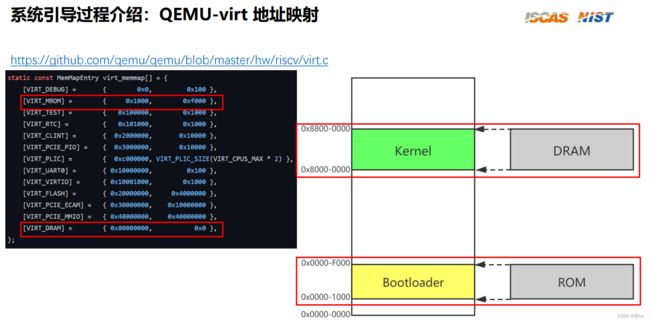
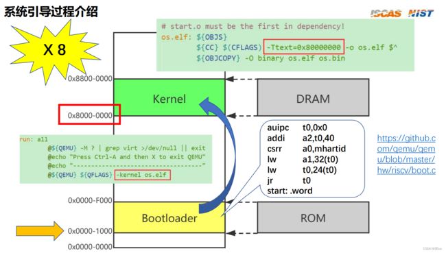
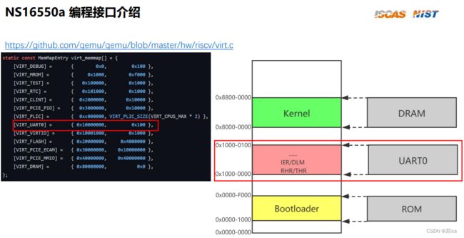
本项目通过QEMU进行模拟,QEMU-virt里面对各个部件的物理地址进行了映射。规定了各个部分的物理内存起始地址以及空间大小。系统上电后,第一步引导器从ROM里面读取指令并执行,然后跳转到内核代码进行执行。即跳转到Kernel出进行执行。
正因如此,内核代码的起始地址便是0x80000000
QEMU virt 有8个hart,但本项目只让第一个hart正常运行,其余的hart进入休眠状态。(比空转功耗更低)。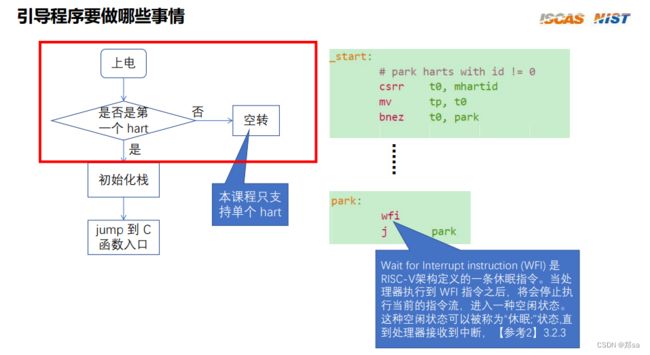
操作系统上电首先进入Machine模式,通过mhartid寄存器读取当前hartid,判断是否为0号hart,除0号hart以外的所有hart都进入休眠状态。
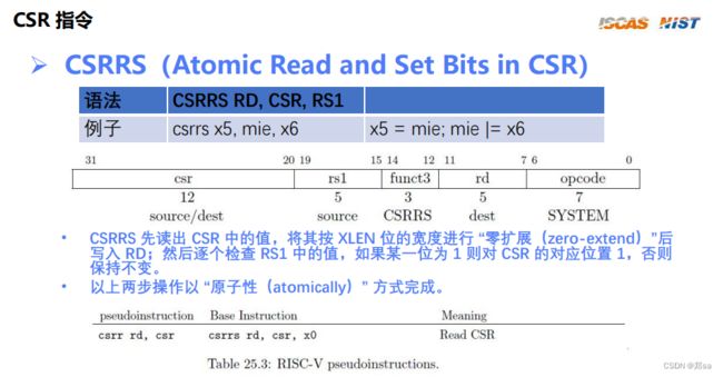
csrr t0, mhartid == csrrs t0,mhartid, x0 即读取mahartid
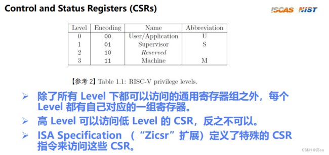
RISC-V操作系统权限分为三个模式:User、Supervisors、Machine;除了每个模式都可以访问的通用寄存器之外,在每个模式下都有自己的一套控制状态寄存器。
#include "platform.h"

	# size of each hart's stack is 1024 bytes
	.equ	STACK_SIZE, 1024

	.global	_start

	.text
_start:
	# park harts with id != 0
	csrr	t0, mhartid		# read current hart id
	mv	tp, t0			# keep CPU's hartid in its tp for later usage.
	bnez	t0, park		# if we're not on the hart 0
					# we park the hart
	# Setup stacks, the stack grows from bottom to top, so we put the
	# stack pointer to the very end of the stack range.
	slli	t0, t0, 10		# shift left the hart id by 1024
	la	sp, stacks + STACK_SIZE	# set the initial stack pointer
					# to the end of the first stack space
	add	sp, sp, t0		# move the current hart stack pointer
					# to its place in the stack space

	j	start_kernel		# hart 0 jump to c

park:
	wfi
	j	park

stacks:
	.skip	STACK_SIZE * MAXNUM_CPU # allocate space for all the harts stacks

	.end				# End of file
如汇编代码所示,判断为0号hart后,开始对栈初始化。一开始定义了每个hart的栈为1024个字节,且定义了总共的栈空间:STACK_SIZE* MAXNUM_CPU
因此,初始化sp应该指向的就是当前hart所占有的栈空间的栈底。
t0左移10位相当于乘以1024,就是移动一个hart所占的栈空间。
由于hart id从0开始,因此一开始的sp就要初始化到0号hart的栈底去。
即为la sp,stacks + STACK_SIZE
再add sp, sp, t0 这里t0是0号 所以sp就相当于没有变了。
初始化完栈后,跳转到start_kernel 进入C语言环境了。
extern void uart_init(void);
extern void uart_puts(char *s);

void start_kernel(void)
{
	uart_init();
	uart_puts("Hello, RVOS!\n");

	while (1) {}; // stop here!
}
UART
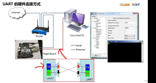
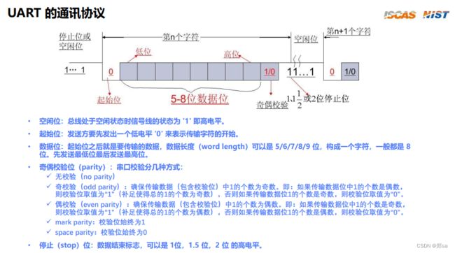
通用异步收发器(Universal Asynchronous Receiver/Transmitter),通常称作UART,是一种串行、异步、全双工的通信协议,在嵌入式领域应用的非常广泛。
即在交叉编译时,板子(QEMU模拟)和控制台连接的串口线所使用的通信协议。
在这里我们使用的串口收发器的型号也是QEMU模拟的真实的一种型号:NS16550a
NS16550a 编程接口介绍
它规定了UART和PLIC(平台级中断控制器)等外设的内存地址映射。之后对UART进行操作即对其的寄存器进行操作
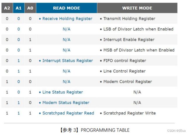
具体操作需要查阅相关手册。
接下来对UART进行初始化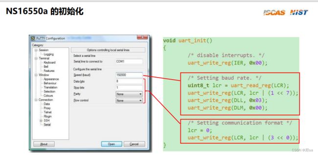
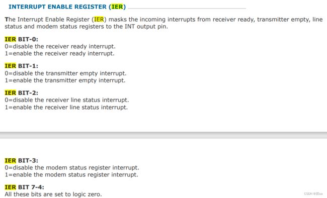
1、关闭中断使能 uart_write_reg(IER, 0x00)
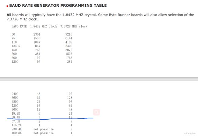
2、设置波特率(传输速率)
2.1:打开波特率使能
2.2通过查表,设置对应寄存器获得相应的波特率
我们使用的是1.8432MHz的时钟频率,设置波特率为38.4K,因此对应寄存器的值应该设置为3
因为UART一个寄存器只有8位,因此需要两个寄存器(最大值有2304)来设置波特率。最高三位寄存器DLM设置为0x00,最低三位寄存器DLL设置为0x03
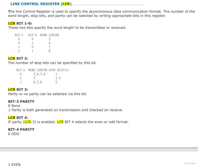
3、设置奇偶校验位和数据传输字长
设置LCR为 00000011 传输字长为8bits 不使用奇偶校验位。
此处介绍轮询处理方式,对UART进行写操作。
1、先判断LSR的第五位是不是为0,为0则继续等待,为1则代表可以进行写操作
2、将数据写入THR寄存器,每次只能写8位(char)
练习7-1
思路:将helloRVOS写入汇编中(最后的0是ASCII码对应的null),用一段内存直接存起来。然后从start_kernel C函数开始,根据执行步骤,写出相应的汇编代码
.data
	array:
	  .byte 'H', 'e', 'l', 'l', 'o', ',', 'R', 'V', 'O', 'S', '!', 0
	  .space 12

	# size of each hart's stack is 1024 bytes
	.equ	STACK_SIZE, 1024
	.equ 	MAXNUM_CPU, 8
	.global	_start

	.text
	.macro uart_read_reg reg1, reg2
		lbu \reg1, 0(\reg2)
	.endm

	.macro uart_write_reg reg, v
		sb \v, 0(\reg)
	.endm

_start:
	# park harts with id != 0
	csrr	t0, mhartid		# read current hart id
	mv	tp, t0			# keep CPU's hartid in its tp for later usage.
	bnez	t0, park		# if we're not on the hart 0
					# we park the hart
	# Setup stacks, the stack grows from bottom to top, so we put the
	# stack pointer to the very end of the stack range.
	slli	t0, t0, 10		# shift left the hart id by 1024
	la	sp, stacks + STACK_SIZE	# set the initial stack pointer
					# to the end of the first stack space
	add	sp, sp, t0		# move the current hart stack pointer
					# to its place in the stack space
	li s0, 0x10000000		#UART0 0x10000000L

	call start_kernel		# hart 0 jump to c
定义了两个宏 用来读和写UART的寄存器,然后把UART的起始地址0x10000000加载进S0,后面方便用。因为,虽然在UART看来是在写它的寄存器,但是在我们模拟过程中,写汇编过程中,其实是对内存地址进行读写。
start_kernel:
	addi sp, sp, -24
	sw s1, 0(sp)
	sw s2, 4(sp)
	sw s3, 8(sp)
	sw s4, 12(sp)
	sw s5, 16(sp)
	sw ra, 20(sp)

	addi s1, s0, 1
	li s2, 0x00
	uart_write_reg s1, s2		#uart_write_reg(IER, 0x00);1
	addi s3, s0, 3
	uart_read_reg s4, s3		#uint8_t lcr = uart_read_reg(LCR);3
	ori s4, s4, 0x80
	uart_write_reg s3, s4		#uart_write_reg(LCR, lcr | (1 << 7));
	li s5, 0x03
	uart_write_reg s0, s5		#uart_write_reg(DLL, 0x03);0
	li s5, 0x00
	uart_write_reg s1, s5		#uart_write_reg(DLM, 0x00);1
	li s5, 3
	uart_write_reg s3, s5		#uart_write_reg(LCR, lcr | (3 << 0));3
	la a0, array
	call uart_puts				#uart_puts("Hello, RVOS!\n");

	lw s1, 0(sp)
	lw s2, 4(sp)
	lw s3, 8(sp)
	lw s4, 12(sp)
	lw s5, 16(sp)
	lw ra, 20(sp)
	addi sp, sp, 24
	ret
这里函数的Prologue和Epilogue都要自己写出来。 里面就是根据通信协议来初始化UART的寄存器,即写到相应的内存上。然后将array 即helloRVOS的起始地址加载进a0,当作函数参数,调用uart_puts函数
uart_puts:
	addi sp, sp, -12
	sw s1, 0(sp)
	sw s2, 4(sp)
	sw ra, 8(sp)

	mv s1, a0
loop:
	lbu a0, 0(s1)
	mv s2, a0
	addi s1, s1, 1
	jal uart_putc
	bnez s2, loop

	lw s1, 0(sp)
	lw s2, 4(sp)
	lw ra, 8(sp)
	addi sp, sp, 12
	ret
将array的起始地址(a0)加载进s1,进入循环,读出当前地址的元素,将读出的元素复制到S2,地址加1(char类型)调用uart_putc函数,之后判断读出来的是否是null,用S2来复制一份读出的数据是为了防止uart_putc返回时,a0被覆盖了。(好像没必要。换个寄存器多省事。。)
uart_putc:
	addi sp, sp, -8
	sw s1, 0(sp)
	sw s2, 4(sp)


	addi s1, s0, 5
	uart_read_reg s2, s1
check:
	ori s2, s2, 32
	beqz s2, check

	uart_write_reg s0, a0

	lw s1, 0(sp)
	lw s2, 4(sp)
	addi sp, sp, 8
	ret
uart_putc采用轮询式 输出数据。s0 + 5 指向的是LSR寄存器 读出LSR寄存器的内容并查看第6位是否为0,不为0则将数据写入s0 即THR寄存器。
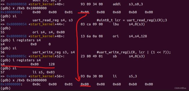
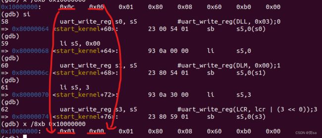
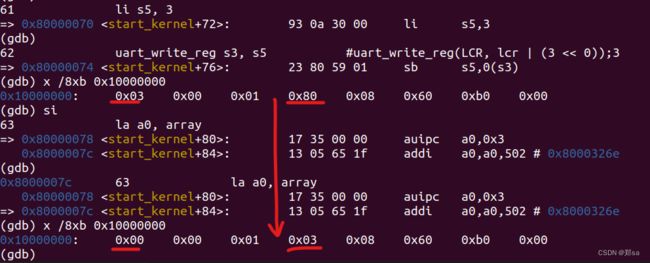
调试结果如下:
0号寄存器那个地址的内存值没动他 为什么自己改变了。。0x00 变为0x0c 不过别的都没问题。
