【RT-Thread】HTTP OTA固件升级
(PS:1024程序员节来写一篇博客!)
这里主要讲解一下HTTP OTA固件升级实践思路及核心代码(已实践),如果有疑问得欢迎评论里探讨!
参考文章:STM32 通用 Bootloader
1. 开发环境
1.1 硬件环境
MCU:STM32F103RET6
AT模块:移远4GCat1无线通讯模块EC200S
RS485:进行数据采集及控制
FLASH:W25Q128
1.2 软件环境
开发工具:RT-Thread Studio
嵌入式实时操作操作系统:RT-Thread
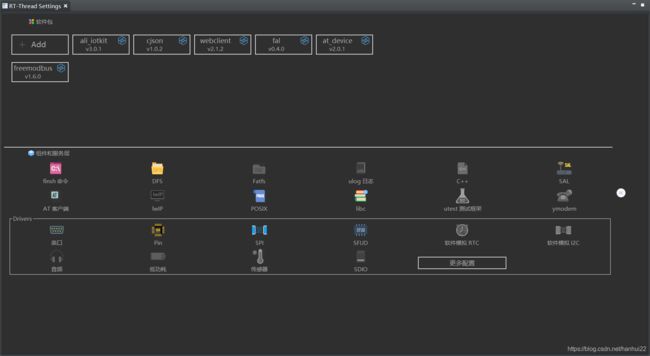
设备驱动、组件、软件包:
1.3 Bootloader生成方法
1.3.1 配置链接
http://iot.rt-thread.com/#/login
1.3.2 硬件配置
串口输出引脚:PB10
支持SPI FLASH:(使用SPI2) CS PB12、CLK PB13、MISO PB14、MOSI PB15
1.3.3 分区表配置
| 分区名 | 所处设备 | 偏移地址 | 大小
| ------------| ------------ | ------------ |
| app | 片内 Flash | 0x10000 | 448KB
| download | 片外 SPI Flash |0x300000 |1024KB
1.3.4 加密压缩
固件使用AES256加密
32位秘钥key:abcdef01234567890123456789abcdef
16位加密IV: abcdef0123456789
1.3.5 固件压缩
压缩方式: fastlz
固件分区名:app
固件版本:2.0.0
2、安装开发步
骤要先配置 FAL 分区,然后解决网络下载升级的问题,最后根据MQTT订阅主题信息OTA升级固件
2.1 配置 FAL 分区
2.2.1 fal_cfg.h文件
#ifndef _FAL_CFG_H_
#define _FAL_CFG_H_

#include
#include

#define NOR_FLASH_DEV_NAME             "norflash0"

/* ===================== Flash device Configuration ========================= */
extern const struct fal_flash_dev stm32_onchip_flash;
extern struct fal_flash_dev nor_flash0;

/* flash device table */
#define FAL_FLASH_DEV_TABLE                                          \
{                                                                    \
    &stm32_onchip_flash,                                             \
    &nor_flash0,                                                     \
}
/* ====================== Partition Configuration ========================== */
#ifdef FAL_PART_HAS_TABLE_CFG
/* partition table */
#define FAL_PART_TABLE                                                                          \
{                                                                                               \
    {FAL_PART_MAGIC_WORD,        "bl",     "onchip_flash",            0,    64*1024,        0}, \
    {FAL_PART_MAGIC_WORD,       "app",     "onchip_flash",      64*1024,    704*1024,       0}, \
    {FAL_PART_MAGIC_WORD, "easyflash", NOR_FLASH_DEV_NAME,            0,    2*1024*1024,    0}, \
    {FAL_PART_MAGIC_WORD,       "ota", NOR_FLASH_DEV_NAME,  2*1024*1024,    1024*1024,      0}, \
    {FAL_PART_MAGIC_WORD,  "download", NOR_FLASH_DEV_NAME,  3*1024*1024,    1024*1024,      0}, \
    {FAL_PART_MAGIC_WORD,   "factory", NOR_FLASH_DEV_NAME,  4*1024*1024,    1024*1024,      0}, \
}
#endif /* FAL_PART_HAS_TABLE_CFG */

#endif /* _FAL_CFG_H_ */
2.1.2 SPI设备驱动初始化、SPI总线挂载初始化、虚拟文件系统初始化
#include
#include "spi_flash.h"
#include "spi_flash_sfud.h"
#include "drv_spi.h"
#include
#include "fal_init_port.h"

#ifdef RT_USING_SPI

void HAL_SPI_MspInit(SPI_HandleTypeDef *spiHandle)
{

    GPIO_InitTypeDef GPIO_InitStruct;
    if (spiHandle->Instance == SPI1)
    {
        /* SPI1 clock enable */
        __HAL_RCC_SPI1_CLK_ENABLE();
        __HAL_RCC_GPIOA_CLK_ENABLE();
        /**SPI1 GPIO Configuration
        PA5     ------> SPI1_SCK
        PA6     ------> SPI1_MISO
        PA7     ------> SPI1_MOSI
        */
        GPIO_InitStruct.Pin = GPIO_PIN_5 | GPIO_PIN_7;
        GPIO_InitStruct.Mode = GPIO_MODE_AF_PP;
        GPIO_InitStruct.Speed = GPIO_SPEED_FREQ_HIGH;
        HAL_GPIO_Init(GPIOA, &GPIO_InitStruct);

        GPIO_InitStruct.Pin = GPIO_PIN_6;
        GPIO_InitStruct.Mode = GPIO_MODE_INPUT;
        GPIO_InitStruct.Pull = GPIO_NOPULL;
        HAL_GPIO_Init(GPIOA, &GPIO_InitStruct);
    }
    else if (spiHandle->Instance == SPI2)
    {
        /* SPI2 clock enable */
        __HAL_RCC_SPI2_CLK_ENABLE();
        __HAL_RCC_GPIOB_CLK_ENABLE();
        /**SPI2 GPIO Configuration
        PB13     ------> SPI2_SCK
        PB14     ------> SPI2_MISO
        PB15     ------> SPI2_MOSI
        */
        GPIO_InitStruct.Pin = GPIO_PIN_13 | GPIO_PIN_15;
        GPIO_InitStruct.Mode = GPIO_MODE_AF_PP;
        GPIO_InitStruct.Speed = GPIO_SPEED_FREQ_HIGH;
        HAL_GPIO_Init(GPIOB, &GPIO_InitStruct);

        GPIO_InitStruct.Pin = GPIO_PIN_14;
        GPIO_InitStruct.Mode = GPIO_MODE_INPUT;
        GPIO_InitStruct.Pull = GPIO_NOPULL;
        HAL_GPIO_Init(GPIOB, &GPIO_InitStruct);
    }
    else if (spiHandle->Instance == SPI3)
    {
        /* SPI2 clock enable */
        __HAL_RCC_SPI3_CLK_ENABLE();
        __HAL_RCC_GPIOB_CLK_ENABLE();
        /**SPI2 GPIO Configuration
        PB3     ------> SPI2_SCK
        PB4     ------> SPI2_MISO
        PB5     ------> SPI2_MOSI
        */
        GPIO_InitStruct.Pin = GPIO_PIN_3 | GPIO_PIN_5;
        GPIO_InitStruct.Mode = GPIO_MODE_AF_PP;
        GPIO_InitStruct.Speed = GPIO_SPEED_FREQ_HIGH;
        HAL_GPIO_Init(GPIOB, &GPIO_InitStruct);

        GPIO_InitStruct.Pin = GPIO_PIN_4;
        GPIO_InitStruct.Mode = GPIO_MODE_INPUT;
        GPIO_InitStruct.Pull = GPIO_NOPULL;
        HAL_GPIO_Init(GPIOB, &GPIO_InitStruct);
    }
}

void HAL_SPI_MspDeInit(SPI_HandleTypeDef *spiHandle)
{

    if (spiHandle->Instance == SPI1)
    {
        /* Peripheral clock disable */
        __HAL_RCC_SPI1_CLK_DISABLE();

        /**SPI1 GPIO Configuration
        PA5     ------> SPI1_SCK
        PA6     ------> SPI1_MISO
        PA7     ------> SPI1_MOSI
        */
        HAL_GPIO_DeInit(GPIOA, GPIO_PIN_5 | GPIO_PIN_6 | GPIO_PIN_7);
    }
    else if (spiHandle->Instance == SPI2)
    {
        /* Peripheral clock disable */
        __HAL_RCC_SPI2_CLK_DISABLE();

        /**SPI2 GPIO Configuration
        PB13     ------> SPI2_SCK
        PB14     ------> SPI2_MISO
        PB15     ------> SPI2_MOSI
        */
        HAL_GPIO_DeInit(GPIOB, GPIO_PIN_13 | GPIO_PIN_14 | GPIO_PIN_15);
    }
    else if (spiHandle->Instance == SPI3)
    {
        /* Peripheral clock disable */
        __HAL_RCC_SPI3_CLK_DISABLE();

        /**SPI2 GPIO Configuration
        PB3     ------> SPI2_SCK
        PB4     ------> SPI2_MISO
        PB5     ------> SPI2_MOSI
        */
        HAL_GPIO_DeInit(GPIOB, GPIO_PIN_3 | GPIO_PIN_4 | GPIO_PIN_5);
    }
}
#endif

#if defined(RT_USING_SFUD)
static int rt_hw_spi_flash_init(void)
{
    __HAL_RCC_GPIOF_CLK_ENABLE();
    rt_hw_spi_device_attach("spi2", "spi20", GPIOB, GPIO_PIN_12);

    if (RT_NULL == rt_sfud_flash_probe("norflash0", "spi20"))
    {
        rt_kprintf("rt_sfud_flash_probe norflash0 spi20 -RT_ERROR\n");
        return -RT_ERROR;
    }
    rt_kprintf("rt_sfud_flash_probe norflash0 spi20 success !!!\n");


    return RT_EOK;
}
INIT_PREV_EXPORT(rt_hw_spi_flash_init);
#endif


int fs_init(void)
{
    /* partition initialized */
    fal_init();
    return 0;
}
INIT_DEVICE_EXPORT(fs_init);
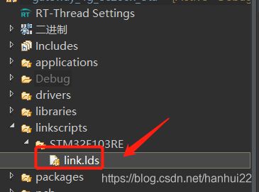
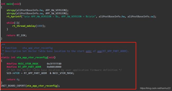
2.1.3 修改RT-Thread Studio工程中的链接脚本的偏移地址
2.2 网络驱动及下载功能
2.2.1 EC200S注册
#include

#ifdef AT_DEVICE_USING_EC200X

#include
#include
#include

#define LOG_TAG                        "at.sample.ec200x"
#include

#define EC200X_PORT_DEIVCE_NAME        "ec200x"

#define EC200X_PORT_POWER_PIN -1
#define EC200X_PORT_STATUS_PIN -1
#define EC200X_PORT_WAKEUP_PIN -1
#define EC200X_PORT_CLIENT_NAME "uart2"
#define EEC200X_PORT_RECV_BUFF_LEN 2048


static struct at_device_ec200x _dev =
{
    EC200X_PORT_DEIVCE_NAME,
    EC200X_PORT_CLIENT_NAME,

    EC200X_PORT_POWER_PIN,
    EC200X_PORT_STATUS_PIN,
    EC200X_PORT_WAKEUP_PIN,
    EEC200X_PORT_RECV_BUFF_LEN,
};

static int ec200x_device_register(void)
{
    struct at_device_ec200x *ec200x = &_dev;

    return at_device_register(&(ec200x->device),
                              ec200x->device_name,
                              ec200x->client_name,
                              AT_DEVICE_CLASS_EC200X,
                              (void *) ec200x);
}
INIT_COMPONENT_EXPORT(ec200x_device_register);
2.2.2 webclient软件包
2.3 阿里云MQTT主题OTA升级固件
2.3.1 阿里云MQTT软件包
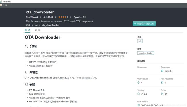
2.3.2 OTA软件包
3 OTA升级固件思路
针对STM32F103RET6的RAM只有64KB,ROM只有512KB,所以如下流程处理:
3.1 通过阿里云物联网平台下发OTA升级的主题JSON格式消息,物联网设备接收后通过cJSON软件包进行解析提取OTA升级有效数据信息,将OTA升级有效数据及升级标志存储到FLASH分区中,重启STM32设备
3.2 上电启动检测是否有升级标志,如果有升级标志,那么只创建OTA固件下载线程,则通过网络HTTP请求下载OTA升级固件到FLASH的download分区中,清除升级标志,下载完成后重新STM32设备
3.3 重启后就进入STM32 BootLoader自动固件升级,解密解压搬运到FLASH的app分区,完成后自动重启
3.4 上电启动检测是否有升级标志,如果没有则进行正常运行升级后固件程序!


