简单的三层架构网络冗余配置实验
实验要求
1、内网ip 地址172.16.0.0/16合理分配
2、SW1/2之间互为备份
3、VRRP / STP / VLAN / TRUNK 均使用
4、所有PC通过DHCP获取IP地址
实验拓扑

地址划分
vlan1:172.16.1.0/25
vlan2:172.16. 1 . 1 2 8 /25
内网骨干链路:172.16.0.0/30;172.16.0.4/30
交换配置
1、ETH-TRUNK
[SW1]int Eth-Trunk 0
[SW1]int g0/0/2
[SW1-GigabitEthernet0/0/2]eth-trunk 0
[SW1-GigabitEthernet0/0/2]int g0/0/3
[SW1-GigabitEthernet0/0/3]eth-trunk 0
[SW2]int Eth-Trunk 0
[SW2-Eth-Trunk0]int g0/0/2
[SW2-GigabitEthernet0/0/2]eth-trunk 0
[SW2-GigabitEthernet0/0/2]int g0/0/3
[SW2-GigabitEthernet0/0/3]eth-trunk 0
检查一下,分别产看vlan,接口0/2、0/3 消失 ,eth-trunk 0 出现
2、vlan:创建vlan,划分vlan
[SW1]vlan 2
[SW2]vlan 2
[SW3]vlan 2
[SW4]vlan 2
将PC2 / 4 划入vlan2
[SW3]int e0/0/4
[SW3-Ethernet0/0/4]port link-type access
[SW3-Ethernet0/0/4]port default vlan 2
[SW4]int e0/0/4
[SW4-Ethernet0/0/4]port link-type access
[SW4-Ethernet0/0/4]port default vlan 2
3、TRUNK干道
经拓扑分析得 ,交换机之间全是trunk干道
[SW1]port-group group-member GigabitEthernet 0/0/4 to GigabitEthernet 0/0/5 Eth-Trunk 0
[SW1-port-group]port link-type trunk
[SW1-port-group]port trunk allow-pass vlan 2 to 3
[SW2]port-group group-member GigabitEthernet 0/0/4 to GigabitEthernet 0/0/5 Eth-Trunk 0
[SW2-port-group]port link-type trunk
[SW2-port-group]port trunk allow-pass vlan 2 to 3
[SW3]port-group group-member GigabitEthernet 0/0/1 to GigabitEthernet 0/0/2
[SW3-port-group]port link-type trunk
[SW3-port-group]port trunk allow-pass vlan 2
[SW4]port-group group-member GigabitEthernet 0/0/1 to GigabitEthernet 0/0/2
[SW4-port-group]port link-type trunk
[SW4-port-group]port trunk allow-pass vlan 2
查验:dis port vlan active
4、STP——MSTP
在所有的交换机上配置
[SW1]stp mode mstp
[SW1-mst-region]region-name A命名
[SW1]stp region-configuration`` [SW1-mst-region]instance 1 vlan 1分组
[SW1-mst-region]instance 2 vlan 2
[SW1-mst-region]active region-configuration 激活stp
未划入分组的自动归入组0
[SW1]stp instance 1 root primary成为STP组1 的主根
[SW1]stp instance 2 root secondary 成为STP组2的备份根
[SW2]stp instance 1 root secondary成为STP组1的备份根
[SW2]stp instance 2 root primary成为STP组2 的主根
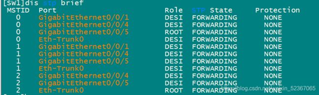
查验:dis stp brief

实现备份分流
在SW3 / 4 上设置边缘接口,提高效率
``[SW4]port-group group-member Ethernet 0/0/3 to Ethernet 0/0/4[SW4-port-group]stp enable[SW4-port-group]stp edged-port enable
5、SVI
[SW1]interface Vlan 1
[SW1-Vlanif1]ip add 172.16.1.1 25
[SW1-Vlanif1]int vlan 2
[SW1-Vlanif2]ip add 172.16.1.129 25
[SW2]interface Vlan 1
[SW2-Vlanif1]ip add 172.16.1.2 25
[SW2-Vlanif1]int vlan 2
[SW2-Vlanif2]ip add 172.16.1.130 25
ping 测试
6、VRRP
设置网关冗余
[SW1]int Vlanif 1进入虚拟接口
[SW1-Vlanif1]vrrp vrid 1 virtual-ip 172.16.1.126配置虚拟IP作为网关
[SW1-Vlanif1]vrrp vrid 1 priority 120修改优先级,时期大于备份网关的优先级
设置下行链路追踪(track)
[SW1-Vlanif1]vrrp vrid 1 track interface g 0/0/1 reduced 30当该接口出现故障降低优先级为30
设置vlan2 的备份网关
[SW1-Vlanif1]int vlan2
[SW1-Vlanif2]vrrp vrid 1 virtual-ip 172.16.1.254
[SW2-Vlanif1]vrrp vrid 1 virtual-ip 172.16.1.126 定义vlan1的网关备份
[SW2-Vlanif1]int vlan 2
[SW2-Vlanif2]vrrp vrid 1 virtual-ip 172.16.1.254 定义vlan2 的网关
[SW2-Vlanif2]vrrp vrid 1 priority 120设置优先级
[SW2-Vlanif2]vrrp vrid 1 track int g 0/0/1 reduced 30设置上行链路追踪
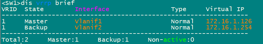
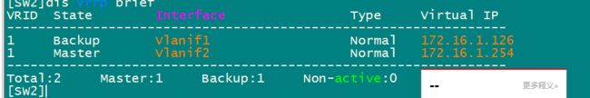
查验设置是否成功:dis vrrp brief
7、DHCP
两个三层交换机配置一样
[SW2]dhcp enable
[SW2]ip pool g1
[SW2-ip-pool-g1] gateway-list 172.16.1.126
[SW2-ip-pool-g1] network 172.16.1.0 mask 255.255.255.128
[SW2-ip-pool-g1] dns-list 114.114.114.114
[SW2]ip pool g2
[SW2-ip-pool-g2] gateway-list 172.16.1.254
[SW2-ip-pool-g2] network 172.16.1.128 mask 255.255.255.128
[SW2-ip-pool-g2] dns-list 114.114.114.114
[SW2]int vlan 1
[SW2-Vlanif1]dhcp select global
[SW2-Vlanif1]int vlan 2
[SW2-Vlanif2]dhcp select global
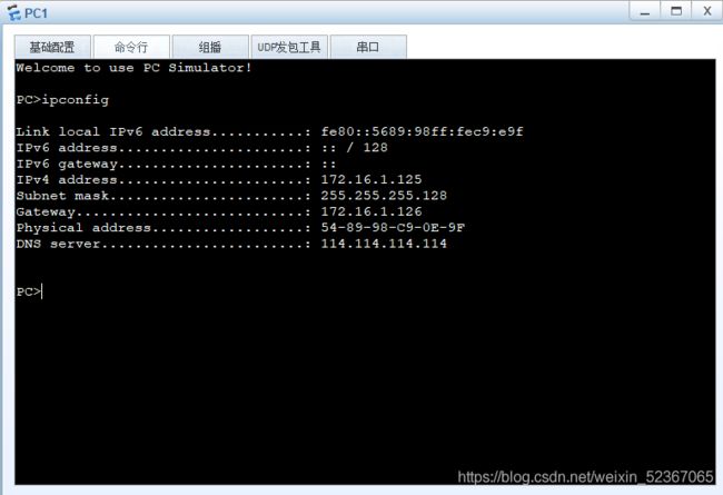
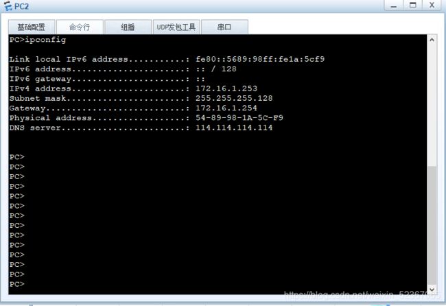
成功获取地址
路由配置
1、底层地址配置
[SW1]vlan 100
[SW1-GigabitEthernet0/0/1]port link-type access
[SW1-GigabitEthernet0/0/1]port default vlan 100
[SW1-GigabitEthernet0/0/1]int vlan 100
[SW1-Vlanif100]ip add 172.16.0.1 30
[SW2]vlan 100
[SW2-vlan100]q
[SW2]int vlan 100
[SW2-Vlanif100]ip add 172.16.0.5 30
[SW2-GigabitEthernet0/0/1]port link-type access
[SW2-GigabitEthernet0/0/1]p d v100
[R1]int g0/0/1
[R1-GigabitEthernet0/0/1]ip add 172.16.0.2 30
[R1-GigabitEthernet0/0/1]int g0/0/2
[R1-GigabitEthernet0/0/2]ip add 172.16.0.6 30
[R1-GigabitEthernet0/0/2]int g0/0/0
[R1-GigabitEthernet0/0/0]ip add 192.168.1.1 24
[ISP]int g0/0/0
[ISP-GigabitEthernet0/0/0]ip add 192.168.1.2 24
ping测试
2、路由
[SW1]ospf 1 router-id 2.2.2.2
[SW1-ospf-1]area 0
[SW1-ospf-1-area-0.0.0.0]network 172.16.0.1 0.0.0.0
[SW1-ospf-1-area-0.0.0.0]q
[SW1-ospf-1]area 1
[SW1-ospf-1-area-0.0.0.1]network 172.16.1.1 0.0.0.0
[SW1-ospf-1-area-0.0.0.1]network 172.16.1.129 0.0.0.0
[SW1-ospf-1-area-0.0.0.1]abr-summary 172.16.1.0 255.255.255.0
[SW2]ospf 1 router-id 2.2.2.22
[SW2-ospf-1]area 0
[SW2-ospf-1-area-0.0.0.0]network 172.16.0.5 0.0.0.0
[SW2-ospf-1-area-0.0.0.0]area 1
[SW2-ospf-1-area-0.0.0.1]network 172.16.1.2 0.0.0.0
[SW2-ospf-1-area-0.0.0.1]network 172.16.1.130 0.0.0.0
[SW2-ospf-1-area-0.0.0.1]abr-summary 172.16.1.0 255.255.255.0
[R1]ospf 1 router-id 1.1.1.1
[R1-ospf-1]area 0
[R1-ospf-1-area-0.0.0.0]network 172.16.0.0 0.0.0.255
设置沉默接口,减少流量洪泛
[SW1-ospf-1]silent-interface all
[SW1-ospf-1]undo silent-interface Eth-Trunk 0
[SW1-ospf-1]undo silent-interface Vlanif 1
[SW2-ospf-1]undo silent-interface Vlanif 100
[SW2-ospf-1]silent-interface all
[SW2-ospf-1]undo silent-interface Eth-Trunk 0
[SW2-ospf-1]undo silent-interface Vlanif 1
[SW2-ospf-1]undo silent-interface Vlanif 100
下放缺省 设置地址转换
[R1]ip route-static 0.0.0.0 0 192.168.1.2
[R1-ospf-1]default-route-advertise
[R1-ospf-1]q
[R1]acl 2000
[R1-acl-basic-2000]rule permit source 172.16.0.0 0.0.255.255
[R1-acl-basic-2000]q
[R1]int g0/0/0
[R1-GigabitEthernet0/0/0]nat outbound 2000
上网测试

检验
全局输入 save 保存配置 ,任意断开设备后,进行上网测试