UFS 4 - UFS Boot
UFS 4 - UFS Boot
- 1 Introduction
- 2 Boot Configuration
- 3 Initialization and boot code download process
-
- 3.1 Partial initialization
-
-
- a) Physical Layer (M-PHY)
- b) Link Layer (UniPro)
- c) UFS Transport Layer (UTP)
- d) Link Configuration
- e) Device Descriptor Reading
-
- 3.2 Boot transfer
- 3.3 Initialization completion
- 4 Initialization process without boot code download
- 5 Boot Logical Unit Operations
- 6 Configurability
- 7 Security
-
- 7.1 Boot Area Protection
基于UFS 3.1
UFS 1-UFS架构简介1
UFS 2 -UFS架构简介2
UFS 3 - UFS RPMB
1 Introduction
Some computing systems can have the need to download the system boot loader from an external non-volatile source. This task can be accomplished through an internal boot ROM contained in the host SOC whose code when executed determines a minimal initialization of the system to start the boot code transfer.
一些计算系统可能需要从外部非易失性源下载系统引导加载程序。该任务可以通过包含在主机 SOC 中的内部引导 ROM 来完成,其代码在执行时确定系统的最小初始化以启动引导代码传输。
Several features of the boot functionality can be configured in order to be adapted to different system requirements.
可以配置引导功能的几个特性,以适应不同的系统要求。
Moreover specific features to ensure boot data integrity and no corruption of boot code are defined.
此外,还定义了确保引导数据完整性和引导代码不损坏的特定功能。
2 Boot Configuration
During boot operation the UFS host controller retrieves the system boot code stored in the UFS device. In this version of the standard, the boot mechanism is defined for a point-to-point topology (see Figure 13.1).
在引导操作期间,UFS 主机控制器检索存储在 UFS 设备中的系统引导代码。在此版本的标准中,引导机制是为点对点拓扑定义的(见图 13.1)。

Two logical units (Boot LU A, Boot LU B) can be used to store the boot code, but only one of them will be active during the boot process. Any logical unit can be configured as “Boot LU A” or “Boot LU B”. No more than one logical unit may be configured as “Boot LU A”, no more than one logical unit may be configured as “Boot LU B”. The logical unit active during boot is mapped onto the Boot well known logical unit (W-LUN = 30h) for read access. In this way, when the host updates the boot code, a fix logical unit number is kept when the active logical unit is swapped from A to B or vice versa.
可以使用两个逻辑单元(Boot LU A、Boot LU B)来存储引导代码,但在引导过程中只有其中一个会处于活动状态。任何逻辑单元都可以配置为“Boot LU A”或“Boot LU B”。不超过一个逻辑单元可以配置为“Boot LU A”,不超过一个逻辑单元可以配置为“Boot LU B”。引导期间活动的逻辑单元映射到引导众所周知的逻辑单元 (W-LUN = 30h) 以进行读取访问。这样,当主机更新引导代码时,当活动逻辑单元从 A 交换到 B时,会保留一个固定的逻辑单元号,反之亦然。
Several configurable fields of the Device Descriptor and the Unit Descriptors determine the device behavior during boot. Device Descriptor and Unit Descriptors are configured by writing the Configuration Descriptor.
设备描述符和单元描述符的几个可配置字段决定了引导期间的设备行为。 Device Descriptor 和 Unit Descriptors 通过编写 Configuration Descriptor 来配置。
For a UFS bootable device, the boot feature is enabled if bBootEnable field in the Device Descriptor is set to 01h.
对于 UFS 可引导设备,如果设备描述符中的 bBootEnable 字段设置为 01h,则启用引导功能。
The characteristics of the logical units used during boot are configured setting the corresponding fields of the Configuration Descriptor;
引导期间使用的逻辑单元的特性通过设置配置描述符的相应字段进行配置;
The number of allocation units (dNumAllocUnits) field configures the logical unit size, and the boot logical unit ID (bBootLunID) field allows to designate the logical unit as being “Boot LU A” or “Boot LU B”. The logical unit active during the boot shall be configured by writing the bBootLunEn attribute, as described in Table 13.1.
分配单元数 (dNumAllocUnits) 字段配置逻辑单元大小,引导逻辑单元 ID (bBootLunID) 字段允许将逻辑单元指定为“Boot LU A”或“Boot LU B”。引导期间活动的逻辑单元应通过写入 bBootLunEn 属性进行配置,如表 13.1 中所述。
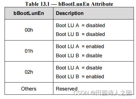
The host should not attempt to set bBootLunEn to ‘Reserved’ values, and UFS device shall generate an error in case of an attempt to set ‘Reserved’ values and not execute the request.
主机不应该尝试将bBootLunEn设置为“Reserved”值,如果尝试设置“Reserved”值,则UFS设备将产生错误并且不执行请求。
When bBootLunEn attribute is 00h the boot feature is disabled, the device behaves as if bBootEnable would be equal to zero.
当bBootLunEn属性为00h时,启动特性被禁用,设备的行为就像bBootEnable等于零一样。
The active boot logical unit will be mapped onto the Boot well known boot logical unit (W-LUN = 30h) once the bBootLunEn has been properly configured.
一旦正确配置了bBootLunEn,活动引导逻辑单元将被映射到boot众所周知的引导逻辑单元(W-LUN = 30h)。
Figure 13.2 shows an example of a UFS device having eight logical units: LU 1 and LU 4 are configured, respectively, as “Boot LU A” and “Boot LU B”. In particular, LU 1 is the active one (bBootLunEn = 01h).
图13.2显示了一个具有八个逻辑单元的UFS设备的示例:LU 1和LU 4分别被配置为“Boot LU a”和“Boot LU B”。其中,LU 1为活动节点(bBootLunEn = 01h)。

3 Initialization and boot code download process
3.1 Partial initialization
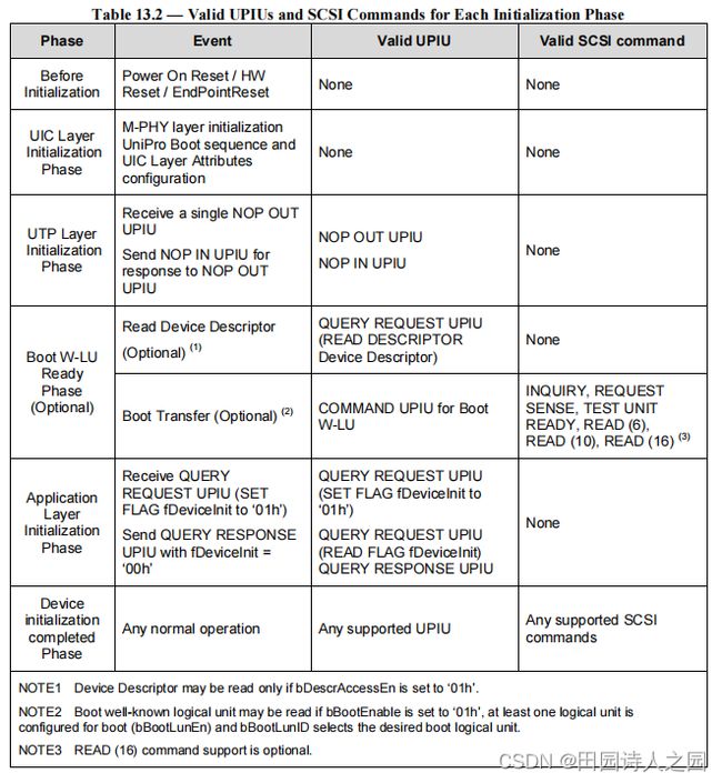
The partial initialization phase starts after power on, or hardware reset, or EndPointReset and involves the entire UFS stack. At the end of this phase, the UniPro boot sequence shall be completed, and the UTP layer shall be capable of accessing Device Descriptor (if the bDescrAccessEn field of the Device Descriptor is ‘01h’) and exchanging UPIU for READ command and TEST UNIT READY command. If the bDescrAccessEn field is ‘00h‘ descriptors will be accessible only after the initialization completion phase.
部分初始化阶段在上电、硬件复位或EndPointReset之后开始,涉及整个UFS堆栈。在此阶段结束时,UniPro启动序列应该完成,并且UTP层应该能够访问设备描述符(如果设备描述符的bDescrAccessEn字段为’ 01h ‘)并将UPIU交换为READ命令和TEST UNIT READY命令。如果bDescrAccessEn字段为’ 00h ',则描述符只有在初始化完成阶段之后才能访问。
Each single layer in the UFS protocol stack executes the initialization process on both UFS host and UFS device sides.
UFS协议栈中的每一层都在UFS主机端和UFS设备端执行初始化过程。
a) Physical Layer (M-PHY)
After reset events, the physical layer will move from DISABLED state to HIBERN8 state.
重置事件发生后,物理层将从DISABLED状态转移到HIBERN8状态
b) Link Layer (UniPro)
On host and device side UniPro boot sequence takes place:
在主机和设备端UniPro启动顺序发生:
-
- The UniPro stack is reset using the DME_RESET.req primitive.
- 使用DME_RESET重置UniPro堆栈。要求的原始。
-
- Wait until the reset completion is indicated by the DME_RESET.cnf_L primitive.
- 等待,直到DME_RESET.cnf_L原语指示重置完成。
-
- The UniPro stack is enabled using the DME_ENABLE.req primitive.
- 使用DME_ENABLE.req基元启用UniPro栈。
-
- Wait until the enable completion is indicated by the DME_ENABLE.cnf_L primitive.
- 等待,直到DME_ENABLE.cnf_L基元指示启用完成。
-
- The UniPro Link StartUp sequence is initiated using the DME_LINKSTARTUP.req primitive. The UniPro Link Startup consists of a series of multiphase handshakes to establish initial link communication in both directions between UFS host and device.
- UniPro链路启动序列是使用DME_LINKSTARTUP.req原件启动的。UniPro链路启动包括一系列多阶段握手,以建立UFS主机和设备之间双向的初始链路通信。
-
- Wait until the link startup completion is indicated by the DME_LINKSTARTUP.cnf_L primitive.
- 等到DME_LINKSTARTUP.cnf_L基元显示链路启动完成。
c) UFS Transport Layer (UTP)
At the end of the UFS Interconnect Layer initialization on both host and device side, the host shall send a NOP OUT UPIU to verify that the device UTP Layer is ready.
在主机和设备侧的UFS互连层初始化结束时,主机应发送一个NOP OUT UPIU,以验证设备UTP层已经准备好。
For some implementations, the device UTP layer may not be initialized yet, therefore the device may not respond promptly to NOP OUT UPIU sending NOP IN UPIU.
对于一些实施方案,设备UTP层可能还没有初始化,因此设备可能不会及时响应NOP OUT UPIU发送NOP IN UPIU。
The host waits until it receives the NOP IN UPIU from the device. When the NOP IN UPIU is received, the host is acknowledged that the UTP layer on the device is ready to execute UTP transactions.
主机等待,直到它收到设备的NOP IN UPIU。当收到NOP IN UPIU时,主机被确认设备上的UTP层已经准备好执行UTP事务。
d) Link Configuration
The host may configure the Link Attributes (i.e., Gear, HS Series, PWM Mode in Rx and Tx) by using DME primitives at UniPro level.
主机可以通过使用UniPro级别的DME原语来配置链路属性(即Gear, HS Series、Rx和Tx的PWM模式)。
e) Device Descriptor Reading
The UFS host may optionally discover relevant device info for the boot process by accessing the Device Descriptor (i.e., Device Class/Subclass, Boot Enable, Boot LUs size, etc.). The UFS host is allowed to access the Device Descriptor only if the bDescrAccessEn is ‘01h’, otherwise this descriptor can be accessed only after the device has fully completed its initialization.
UFS主机可以选择通过访问设备描述符来发现启动过程中的相关设备信息(即,设备类别/子类别,启动启用,启动单元大小等)。只有当bDescrAccessEn为’01h’时,UFS主机才允许访问设备描述符,否则只有在设备完全完成初始化后才能访问这个描述符。
3.2 Boot transfer
The following steps can be executed only if bBootEnable field is set.
只有当bBootEnable字段被设置时,才能执行以下步骤。
Boot code download
At first, the UFS host issues a TEST UNIT READY command to the Boot well known logical unit to verify if the latter can be accessed. If the command succeeds, the UFS host reads the Boot well known logical unit by issuing SCSI READ commands and the UFS device will start to send the boot code on the Upstream Link. During this phase only the Boot well known logical unit is accessible: this logical unit shall accept read commands, while other logical units may not be ready.
首先,UFS主机向Boot well known逻辑单元发出TEST UNIT READY命令,验证后者是否可以被访问。如果命令成功,UFS主机通过发出SCSI READ命令来读取Boot well known逻辑单元,UFS设备将开始在上行链路上发送启动代码。在这个阶段,只有Boot well known逻辑单元可以访问:这个逻辑单元应接受读取命令,而其他逻辑单元可能还没有准备好。
3.3 Initialization completion
After the host has completed the boot code download from the Boot well known logical unit, the initialization process proceeds as described in the following. The host sets the fDeviceInit flag to “01h” to communicate to the UFS device that it can complete its initialization. The device shall reset the fDeviceInit flag when the initialization is complete. The host polls the fDeviceInit flag to check the completion of the process. When the fDeviceInit is reset, the device is ready to accept any command.
在主机完成了从Boot well known逻辑单元的引导代码下载后,初始化过程将按照下面的描述进行。主机将fDeviceInit标志设置为 “01h”,向UFS设备传达它可以完成初始化。设备应在初始化完成后重置fDeviceInit标志。主机轮询fDeviceInit标志以检查该过程的完成情况。当fDeviceInit被重置时,设备已经准备好接受任何命令。

4 Initialization process without boot code download
If the boot process is not enabled on the UFS device, or it is not supported by the device class, or the host does not need to transfer the boot code, the host executes the initialization process as described in 13.1.3, omitting the boot transfer phase.
如果在UFS设备上没有启用启动过程,或者设备等级不支持,或者主机不需要传输启动代码,那么主机执行13.1.3所述的初始化过程,省略启动传输阶段。
5 Boot Logical Unit Operations
The Boot well known logical unit is read only, therefore the boot code can be stored only writing the boot logical units (A or B).
启动众所周知的逻辑单元是只读的,因此,启动代码只能存储写入启动逻辑单元(A或B)。
Boot logical units are written to store the boot code during the system manufacturing phase and they may be also updated during the system lifecycle. These logical units can be read to verify their content.
在系统制造阶段,启动逻辑单元被写来存储启动代码,它们也可能在系统生命周期内被更新。这些逻辑单元可以被读取以验证其内容。
Therefore the following operations are permitted on the Boot logical units:
因此,允许对Boot逻辑单元进行以下操作:
-
- boot code write – for boot code upload/update
-
- boot code read – to verify the content programmed
-
- boot code removal – to remove the content of the Boot logical unit
These operations can be executed regardless the bBootEnable field value in the Device Descriptor. Boot logical units (A or B) can be write protected using the methods described in 12.3, Device Data Protection.
无论设备描述符中的bBootEnable字段值如何,都可以执行这些操作。启动逻辑单元(A或B)可以使用12.3,设备数据保护中描述的方法进行写保护。
6 Configurability
The boot process is configurable through several parameters in the Configuration Descriptor to adapt it to different usage models and system features.
引导过程可通过配置描述符中的多个参数进行配置,以使其适应不同的使用模型和系统功能。
The following parameters refer to boot capabilities.
以下参数涉及启动功能。
- Device Descriptor parameters: 设备描述符参数
- bBootEnable (Boot Enable)
- bDescrAccessEn (Descriptor Access Enable)
- bInitPowerMode (Initial Power Mode)
- bInitActiveICCLevel (Initial Active ICC Level)
- Unit Descriptor parameters for Boot LU A and Boot LU B: (Boot LU A 和 Boot LU B 的单元描述符参数)
- bLUEnable (Logical Unit Enable)
- bBootLunID (Boot LUN ID)
- bLUWriteProtect (Logical Unit Write Protect)
- bMemoryType (Memory Type)
- dNumAllocUnits (Number of Allocation Units)
- bDataReliability (Data Reliability)
- bLogicalBlockSize (Logical Block Size)
- bProvisioningType (Provisioning Type)
NOTE These parameters are non volatile and they may be programmed during the system manufacturing phase.
注:这些参数是非易失性的,它们可以在系统制造阶段进行编程。
In addition to the parameters mentioned, the following attributes are relevant for device initialization and boot
除了提到的参数外,以下属性与设备初始化和引导相关
- bBootLunEn (Boot LUN Enable)
- bRefClkFreq (Reference Clock Frequency value)
7 Security
7.1 Boot Area Protection
Boot areas might be protected in order to avoid boot code alteration by a third party: the write protection mechanism for the boot logical units can be defined configuring the corresponding bLUWriteProtect parameter of the Unit Descriptor.
可以保护引导区域以避免引导代码被第三方更改:引导逻辑单元的写保护机制可以通过配置单元描述符的相应 bLUWriteProtect 参数来定义。
In particular, the boot logical units may be permanently write protected or power-on write protected. In case of power-on write protection, the boot logical units can be written only when the fPowerOnWPEn flag is equal to zero.
特别地,引导逻辑单元可以被永久写保护或上电写保护。在上电写保护的情况下,只有当 fPowerOnWPEn 标志等于 0 时才能写入引导逻辑单元。