37款传感器与执行器的提法,在网络上广泛流传,其实Arduino能够兼容的传感器模块肯定是不止这37种的。鉴于本人手头积累了一些传感器和执行器模块,依照实践出真知(一定要动手做)的理念,以学习和交流为目的,这里准备逐一动手尝试系列实验,不管成功(程序走通)与否,都会记录下来—小小的进步或是搞不掂的问题,希望能够抛砖引玉。
【Arduino】168种传感器模块系列实验(资料代码+仿真编程+图形编程)
实验一百三十六:0.91寸OLED液晶屏显示模块 IIC 12832液晶屏 兼容3.3v-5V
【Arduino】168种传感器模块系列实验(资料代码+仿真编程+图形编程)
实验一百三十六:0.91寸OLED液晶屏显示模块 IIC 12832液晶屏 兼容3.3v-5V
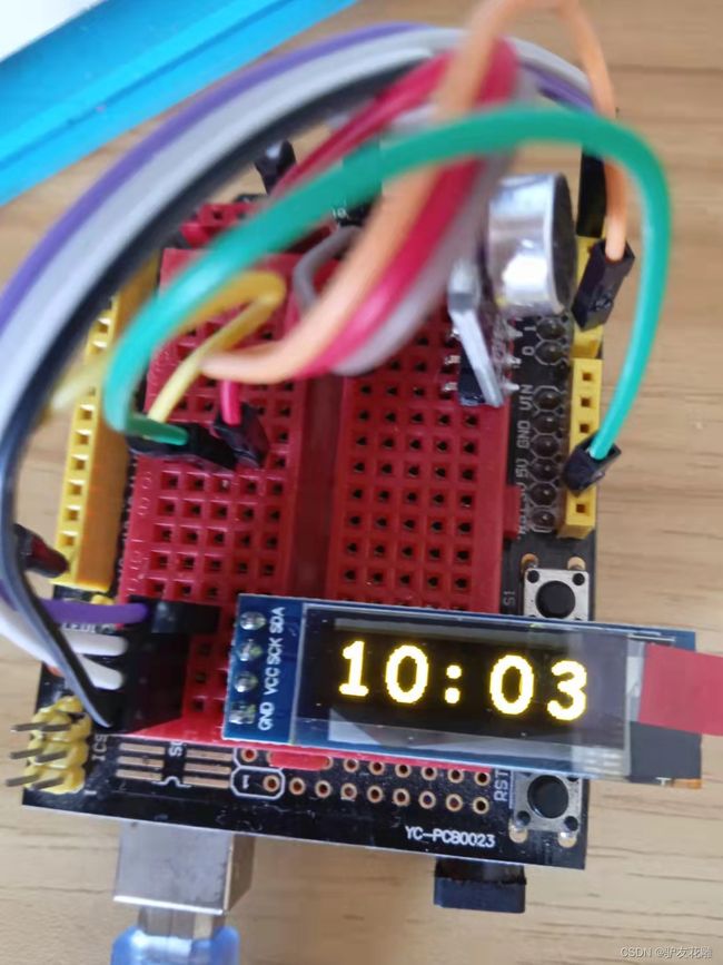
项目十九:OLED屏显示时钟
实验开源代码
/*
【Arduino】168种传感器模块系列实验(资料代码+仿真编程+图形编程)
实验一百三十六:0.91寸OLED液晶屏显示模块 IIC 12832液晶屏 兼容3.3v-5V
项目十九:OLED屏显示时钟
实验接线:
oled模块 Ardunio Uno
GND---------GND接地线
VCC---------5V 接电源
SDA---------A4
SCL ------- A5
*/
#include "ssd1306.h"
uint32_t lastMillis;
uint8_t hours = 10;
uint8_t minutes = 02;
uint8_t seconds = 0;
void printSeconds() {
if (seconds & 1) {
ssd1306_printFixed(54, 2, ":", STYLE_NORMAL);
}
else {
ssd1306_printFixed(54, 2, " ", STYLE_NORMAL);
}
}
void printMinutes() {
char minutesStr[3] = "00";
minutesStr[0] = '0' + minutes / 10;
minutesStr[1] = '0' + minutes % 10;
ssd1306_printFixed(78, 2, minutesStr, STYLE_NORMAL);
}
void printHours() {
char hoursStr[3] = "00";
hoursStr[0] = '0' + hours / 10;
hoursStr[1] = '0' + hours % 10;
ssd1306_printFixed(6, 2, hoursStr, STYLE_NORMAL);
}
void setup() {
//如果您需要使用 128x32 显示,请将下面的行替换为 ssd1306_128x32_i2c_init()
ssd1306_128x32_i2c_init();
ssd1306_fillScreen(0x00);
ssd1306_setFixedFont(comic_sans_font24x32_123);
lastMillis = millis();
printHours();
printMinutes();
}
void loop() {
if ((uint32_t)(millis() - lastMillis) >= 1000) {
lastMillis += 1000;
if (++seconds > 59)
{
seconds = 0;
if (++minutes > 59)
{
minutes = 0;
if (++hours > 23)
{
hours = 0;
}
printHours();
}
printMinutes();
}
printSeconds();
}
}
Arduino实验场景图
【Arduino】168种传感器模块系列实验(资料代码+仿真编程+图形编程)
实验一百三十六:0.91寸OLED液晶屏显示模块 IIC 12832液晶屏 兼容3.3v-5V
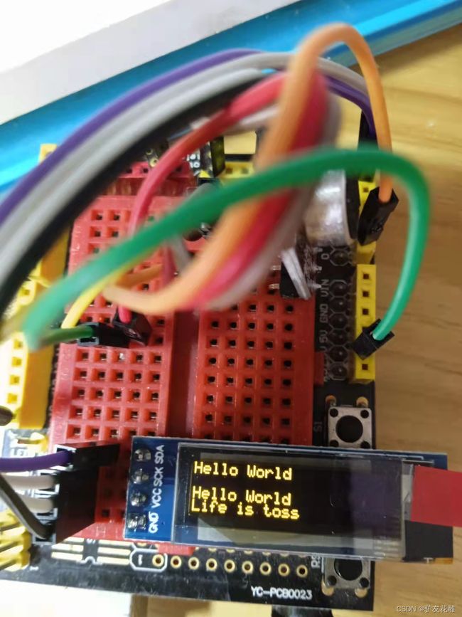
项目二十:OLED屏显示自动翻滚文本字符
实验开源代码
/*
【Arduino】168种传感器模块系列实验(资料代码+仿真编程+图形编程)
实验一百三十六:0.91寸OLED液晶屏显示模块 IIC 12832液晶屏 兼容3.3v-5V
项目二十:OLED屏显示自动翻滚文本字符
实验接线:
oled模块 Ardunio Uno
GND---------GND接地线
VCC---------5V 接电源
SDA---------A4
SCL ------- A5
*/
#include "ssd1306.h"
#include "ssd1306_console.h"
void setup() {
/* Replace the line below with the display initialization function, you want to use */
ssd1306_128x32_i2c_init();
ssd1306_clearScreen();
/* Set font to use with console */
ssd1306_setFixedFont(ssd1306xled_font6x8);
}
void loop() {
ssd1306_print( "Hello World\n" );
delay(500);
ssd1306_print( "Life is toss\n" );
delay(500);
}
Arduino实验场景图
【Arduino】168种传感器模块系列实验(资料代码+仿真编程+图形编程)
实验一百三十六:0.91寸OLED液晶屏显示模块 IIC 12832液晶屏 兼容3.3v-5V
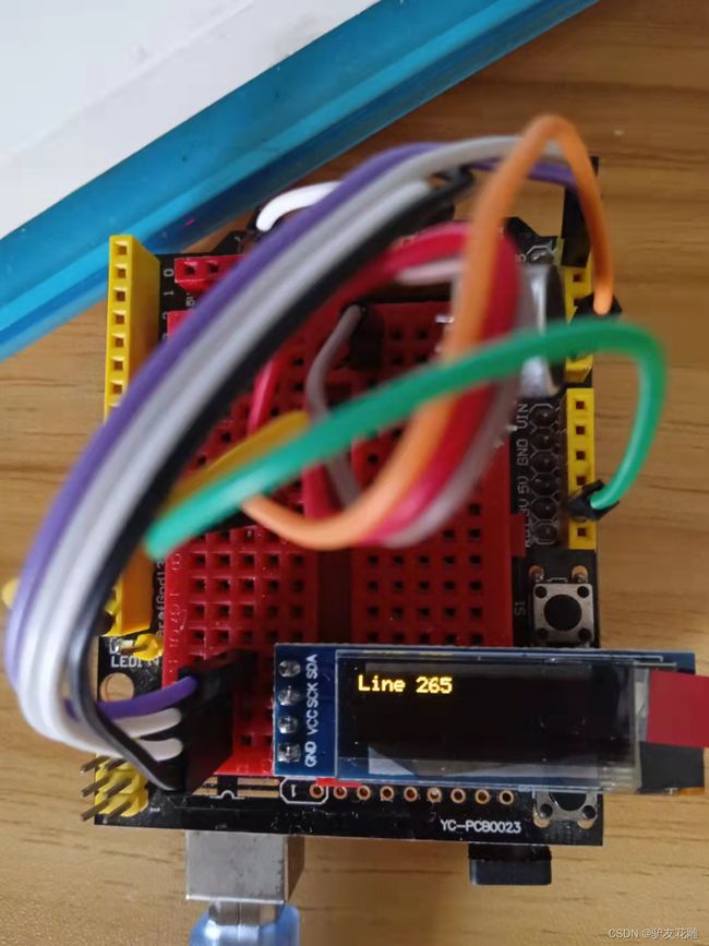
项目二十一:自动计数器
实验开源代码
/*
【Arduino】168种传感器模块系列实验(资料代码+仿真编程+图形编程)
实验一百三十六:0.91寸OLED液晶屏显示模块 IIC 12832液晶屏 兼容3.3v-5V
项目二十一:自动计数器
实验接线:
oled模块 Ardunio Uno
GND---------GND接地线
VCC---------5V 接电源
SDA---------A4
SCL ------- A5
*/
#include "ssd1306.h"
#include "ssd1306_console.h"
Ssd1306Console console;
void setup(){
/* Replace the line below with the display initialization function, you want to use */
ssd1306_128x32_i2c_init();
ssd1306_clearScreen();
/* Set font to use with console */
ssd1306_setFixedFont(ssd1306xled_font6x8);
}
void loop(){
static uint8_t i = 0;
/* Here use any methods, provided by Arduino Print class */
console.print("Line ");
console.print( i );
i++;
delay(500);
console.println("");
}
Arduino实验场景图
【Arduino】168种传感器模块系列实验(资料代码+仿真编程+图形编程)
实验一百三十六:0.91寸OLED液晶屏显示模块 IIC 12832液晶屏 兼容3.3v-5V
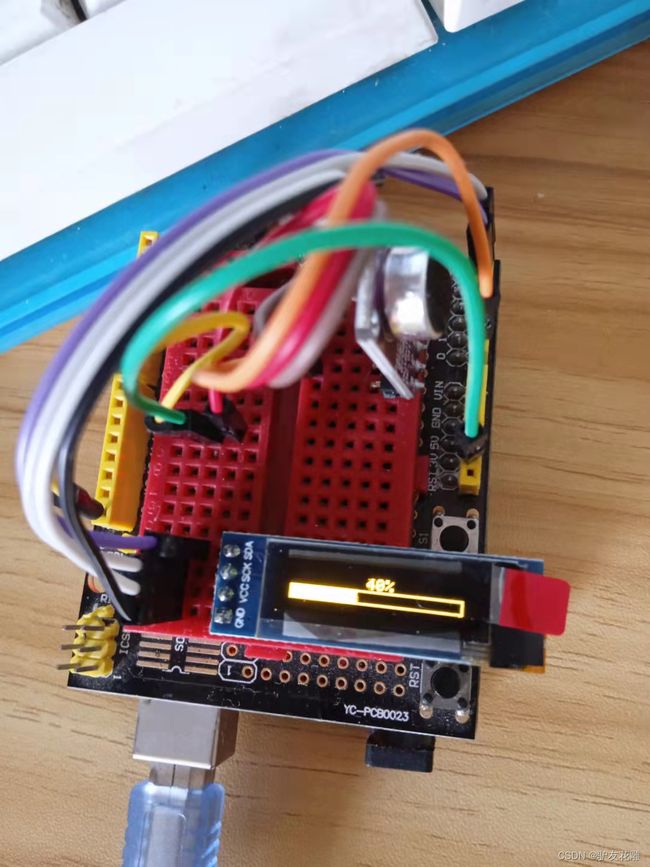
项目二十二:OLED屏显示进度条
实验开源代码
/*
【Arduino】168种传感器模块系列实验(资料代码+仿真编程+图形编程)
实验一百三十六:0.91寸OLED液晶屏显示模块 IIC 12832液晶屏 兼容3.3v-5V
项目二十二:OLED屏显示进度条
实验接线:
oled模块 Ardunio Uno
GND---------GND接地线
VCC---------5V 接电源
SDA---------A4
SCL ------- A5
*/
#include "ssd1306.h"
void setup(){
/* Replace the line below with ssd1306_128x32_i2c_init() if you need to use 128x32 display */
ssd1306_128x32_i2c_init();
ssd1306_fillScreen(0x00);
ssd1306_setFixedFont(ssd1306xled_font6x8);
}
int progress = 0;
void loop(){
ssd1306_drawProgressBar( progress );
progress++;
if ( progress > 100 )
{
progress = 0;
delay( 1000 );
}
else
{
delay( 30 );
}
}
Arduino实验场景图
【Arduino】168种传感器模块系列实验(资料代码+仿真编程+图形编程)
实验一百三十六:0.91寸OLED液晶屏显示模块 IIC 12832液晶屏 兼容3.3v-5V
项目二十三:黄色屏声音可视化器
实验开源代码
/*
【Arduino】168种传感器模块系列实验(资料代码+仿真编程+图形编程)
实验一百三十六:0.91寸OLED液晶屏显示模块 IIC 12832液晶屏 兼容3.3v-5V
项目二十三:黄色屏声音可视化器
实验接线: max9814接A0
oled模块 Ardunio Uno
GND---------GND接地线
VCC---------5V 接电源
SDA---------A4
SCL ------- A5
*/
#include "arduinoFFT.h"
#include
#include
#define SAMPLES 64 // power of 2
#define SAMPLING_FREQ 8000 // 12 kHz Fmax = sampleF /2
#define AMPLITUDE 100 // 灵敏度
#define FREQUENCY_BANDS 14
#define SCREEN_WIDTH 128
#define SCREEN_HEIGHT 32
#define BARWIDTH 11
#define BARS 11
#define ANALOG_PIN A0
#define OLED_RESET -1 // 重置引脚 #(如果共享 Arduino 重置引脚,则为 -1)
Adafruit_SSD1306 display(SCREEN_WIDTH, SCREEN_HEIGHT, &Wire, OLED_RESET);
double vImag[SAMPLES];
double vReal[SAMPLES];
unsigned long sampling_period_us;
arduinoFFT fft = arduinoFFT(vReal, vImag, SAMPLES, SAMPLING_FREQ);
//调整参考以去除背景噪声
float reference = log10(60.0);
double coutoffFrequencies[FREQUENCY_BANDS];
void setup() {
// SSD1306_SWITCHCAPVCC = generate display voltage from 3.3V internally
if (!display.begin(SSD1306_SWITCHCAPVCC, 0x3C)) { // Address 0x3C for 128x32
for (;;); // Don't proceed, loop forever
}
// Setup display
display.clearDisplay();
display.display();
display.setRotation(0);
display.invertDisplay(false);
sampling_period_us = (1.0 / SAMPLING_FREQ ) * pow(10.0, 6);
// 计算截止频率,以对数标度为基数 POt
double basePot = pow(SAMPLING_FREQ / 2.0, 1.0 / FREQUENCY_BANDS);
coutoffFrequencies[0] = basePot;
for (int i = 1 ; i < FREQUENCY_BANDS; i++ ) {
coutoffFrequencies[i] = basePot * coutoffFrequencies[i - 1];
}
// 绘制虚线以分离频段
for (int i = 0; i < BARS - 1 ; i++) {
for (int j = 0; j < SCREEN_HEIGHT ; j += 4) {
display.writePixel((i + 1)*BARWIDTH + 2 , j, SSD1306_WHITE );
}
}
display.drawRect(0, 0, SCREEN_WIDTH, SCREEN_HEIGHT, SSD1306_WHITE);
}
int oldHeight[20];
int oldMax[20];
double maxInFreq;
void loop() {
// 采样
for (int i = 0; i < SAMPLES; i++) {
unsigned long newTime = micros();
int value = analogRead(ANALOG_PIN);
vReal[i] = value;
vImag[i] = 0;
while (micros() < (newTime + sampling_period_us)) {
yield();
}
}
// 计算 FFT
fft.DCRemoval();
fft.Windowing(FFT_WIN_TYP_HAMMING, FFT_FORWARD);
fft.Compute(FFT_FORWARD);
fft.ComplexToMagnitude();
double median[20];
double max[20];
int index = 0;
double hzPerSample = (1.0 * SAMPLING_FREQ) / SAMPLES; //
double hz = 0;
double maxinband = 0;
double sum = 0;
int count = 0;
for (int i = 2; i < (SAMPLES / 2) ; i++) {
count++;
sum += vReal[i];
if (vReal[i] > max[index] ) {
max[index] = vReal[i];
}
if (hz > coutoffFrequencies[index]) {
median[index] = sum / count;
sum = 0.0;
count = 0;
index++;
max[index] = 0;
median[index] = 0;
}
hz += hzPerSample;
}
// 计算每个频段的中值和最大值
if ( sum > 0.0) {
median[index] = sum / count;
if (median[index] > maxinband) {
maxinband = median[index];
}
}
int bar = 0;
for (int i = FREQUENCY_BANDS - 1; i >= 3; i--) {
int newHeight = 0;
int newMax = 0;
// 计算实际分贝
if (median[i] > 0 && max[i] > 0 ) {
newHeight = 20.0 * (log10(median[i] ) - reference);
newMax = 20.0 * (log10(max[i] ) - reference);
}
// 调整最小和最大级别
if (newHeight < 0 || newMax < 0) {
newHeight = 1;
newMax = 1;
}
if (newHeight >= SCREEN_HEIGHT - 2) {
newHeight = SCREEN_HEIGHT - 3;
}
if (newMax >= SCREEN_HEIGHT - 2) {
newMax = SCREEN_HEIGHT - 3;
}
int barX = bar * BARWIDTH + 5;
// 删除旧水平中位数
if (oldHeight[i] > newHeight) {
display.fillRect(barX, newHeight + 1, 7, oldHeight[i], SSD1306_BLACK);
}
// 删除旧的最大级别
if ( oldMax[i] > newHeight) {
for (int j = oldMax[i]; j > newHeight; j -= 2) {
display.drawFastHLine(barX , j, 7, SSD1306_BLACK);
}
}
// 绘制新的最大级别
for (int j = newMax; j > newHeight; j -= 2) {
display.drawFastHLine(barX , j, 7, SSD1306_WHITE);
}
// 绘制新的级别中位数
display.fillRect(barX , 1, 7, newHeight, SSD1306_WHITE);
oldMax[i] = newMax;
oldHeight[i] = newHeight;
bar++;
}
display.drawFastHLine(0 , SCREEN_HEIGHT - 1, SCREEN_WIDTH, SSD1306_WHITE);
display.display();
}
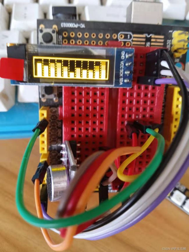
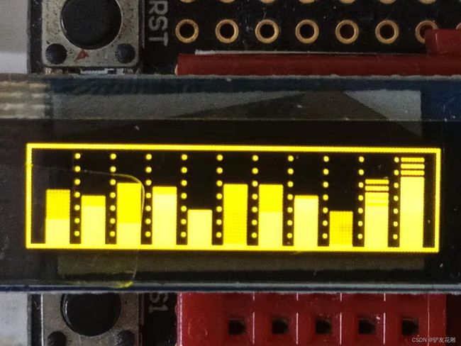
Arduino实验场景图
【Arduino】168种传感器模块系列实验(资料代码+仿真编程+图形编程)
实验一百三十六:0.91寸OLED液晶屏显示模块 IIC 12832液晶屏 兼容3.3v-5V
项目二十三:黄色屏声音可视化器
实验视频剪辑
https://v.youku.com/v_show/id_XNTgwODkzMzY3Mg==.html?spm=a2hcb.playlsit.page.1
【Arduino】168种传感器模块系列实验(资料代码+仿真编程+图形编程)
实验一百三十六:0.91寸OLED液晶屏显示模块 IIC 12832液晶屏 兼容3.3v-5V
项目二十四:Arduino OLED 频谱分析仪
实验开源代码
/*
【Arduino】168种传感器模块系列实验(资料代码+仿真编程+图形编程)
实验一百三十六:0.91寸OLED液晶屏显示模块 IIC 12832液晶屏 兼容3.3v-5V
项目二十四:Arduino OLED 频谱分析仪
实验接线:
oled模块 Ardunio Uno
GND---------GND接地线
VCC---------5V 接电源
SDA---------A4
SCL ------- A5
*/
#include
#include
#include
// These are user-adjustable
#define LOG_OUTPUT // Uncomment to enable logarithmic output (exchanges absolute resoluton for more readable output; may require different below params)
#define SAMPLING_FREQUENCY 15000 // Sampling frequency (Actual max measured frequency captured is half)
#define TIME_FACTOR 2 // Smoothing factor (lower is more dynamic, higher is smoother) ranging from 1 to 10+
#define SCALE_FACTOR 13 // Direct scaling factor (raise for higher bars, lower for shorter bars)
#ifdef LOG_OUTPUT
const float log_scale = 64. / log(64. / SCALE_FACTOR + 1.); // Attempts to create an equivalent to SCALE_FACTOR for log function
#endif
const float coeff = 1. / TIME_FACTOR; // Time smoothing coefficients (used to factor in previous data)
const float anti_coeff = (TIME_FACTOR - 1.) / TIME_FACTOR;
const unsigned int sampling_period_us = round(1000000 * (2.0 / SAMPLING_FREQUENCY)); // Sampling period (doubled to account for overclock)
int8_t data[64], buff[32]; // used to store FFT input/output and past data
unsigned long microseconds; // used for timekeeping
int summ, avg; // used for DC bias elimination
NanoEngine<TILE_32x32_MONO> engine; // declares nanoengine
void setup()
{
OSCCAL = 240; // Overclocks the MCU to around 30 MHz, set lower if this causes instability, raise if you can/want
ADCSRA &= ~(bit (ADPS0) | bit (ADPS1) | bit (ADPS2)); // clear ADC prescaler bits
ADCSRA |= bit (ADPS2); // sets ADC clock in excess of 10kHz
ADCSRA |= bit (ADPS0);
ssd1306_128x64_i2c_init(); // initializes OLED
ssd1306_clearScreen(); // clears OLED
engine.begin(); // inititalizes nanoengine
};
void loop()
{
summ = 0;
for (int i = 0; i < 64; i++) {
microseconds = micros();
data[i] = ((analogRead(A0)) >> 2) - 128; // Fitting analogRead data (range:0 - 1023) to int8_t array (range:-128 - 127)
summ += data[i];
while (micros() < (microseconds + sampling_period_us)) { // Timing out uC ADC to fulfill sampling frequency requirement
}
}
// Eliminating remaining DC component (produces usable data in FFT bin #0, which is usually swamped by DC bias)
avg = summ / 64;
for (int i = 0; i < 64; i++) {
data[i] -= avg;
}
fix_fftr(data, 6, 0); // Performing real FFT
// Time smoothing by user-determined factor and user-determined scaling
for (int count = 0; count < 32; count++) {
if (data[count] < 0) data[count] = 0; // Eliminating negative output of fix_fftr
#ifdef LOG_OUTPUT
else data[count] = log_scale * log((float)(data[count] + 1)); // Logarithmic function equivalent to SCALING_FACTOR*log2(x+1)
#else
else data[count] *= SCALE_FACTOR; // Linear scaling up according to SCALE_FACTOR
#endif
data[count] = (float)buff[count] * anti_coeff + (float)data[count] * coeff; // Smoothing by factoring in past data
buff[count] = data[count]; // Storing current output as next frame's past data
if (data[count] > 63) data[count] = 63; // Capping output at screen height
}
// Output to SSD1306 using nanoengine canvas from library
engine.refresh(); // Mark entire screen to be refreshed
engine.canvas.clear(); // Clear canvas as previous data
for (int i = 0; i < 8; i++) {
engine.canvas.drawVLine(i * 4, 31 - (data[i] + 1), 31); // Draw to canvas data for lower-leftest sector (FFT bins 0 - 7, lower half)
}
engine.canvas.blt(0, 32); // Outputs canvas to OLED with an offset (x pixels, y pixels)
engine.canvas.clear();
for (int i = 0; i < 8; i++) {
if (data[i] > 31) engine.canvas.drawVLine(i * 4, 31 - (data[i] - 31), 31); // Draw to canvas data for upper-leftest sector (FFT bins 0 - 7, upper half)
}
engine.canvas.blt(0, 0);
engine.canvas.clear();
for (int i = 8; i < 16; i++) {
engine.canvas.drawVLine((i - 8) * 4, 31 - (data[i] + 1), 31); // FFT bins 8 - 15, lower half
}
engine.canvas.blt(32, 32);
engine.canvas.clear();
for (int i = 8; i < 16; i++) {
if (data[i] > 31) engine.canvas.drawVLine((i - 8) * 4, 31 - (data[i] - 31), 31); // FFT bins 9 - 15, upper half
}
engine.canvas.blt(32, 0);
engine.canvas.clear();
for (int i = 16; i < 24; i++) {
engine.canvas.drawVLine((i - 16) * 4, 31 - (data[i] + 1), 31); // FFT bins 16 - 23, lower half
}
engine.canvas.blt(64, 32);
engine.canvas.clear();
for (int i = 16; i < 24; i++) {
if (data[i] > 31) engine.canvas.drawVLine((i - 16) * 4, 31 - (data[i] - 31), 31); // FFT bins 16 - 23, upper half
}
engine.canvas.blt(64, 0);
engine.canvas.clear();
for (int i = 24; i < 32; i++) {
engine.canvas.drawVLine((i - 24) * 4, 31 - (data[i] + 1), 31); // FFT bins 24 - 31, lower half
}
engine.canvas.blt(96, 32);
engine.canvas.clear();
for (int i = 24; i < 32; i++) {
if (data[i] > 31) engine.canvas.drawVLine((i - 24) * 4, 31 - (data[i] - 31), 31); // FFT bins 24 - 31, upper half
}
engine.canvas.blt(96, 0);
}
Arduino实验场景图
【Arduino】168种传感器模块系列实验(资料代码+仿真编程+图形编程)
实验一百三十六:0.91寸OLED液晶屏显示模块 IIC 12832液晶屏 兼容3.3v-5V
项目二十四:Arduino OLED 频谱分析仪
实验视频剪辑
https://v.youku.com/v_show/id_XNTgwOTAzMzIxNg==.html?spm=a2hcb.playlsit.page.1
【Arduino】168种传感器模块系列实验(资料代码+仿真编程+图形编程)
实验一百三十六:0.91寸OLED液晶屏显示模块 IIC 12832液晶屏 兼容3.3v-5V
项目二十五:简单的文本反转
实验开源代码
/*
【Arduino】168种传感器模块系列实验(资料代码+仿真编程+图形编程)
实验一百三十六:0.91寸OLED液晶屏显示模块 IIC 12832液晶屏 兼容3.3v-5V
项目二十五:简单的文本反转
实验接线:
oled模块 Ardunio Uno
GND---------GND接地线
VCC---------5V 接电源
SDA---------A4
SCL ------- A5
*/
#include
#include "SSD1306Ascii.h"
#include "SSD1306AsciiWire.h"
// 0X3C+SA0 - 0x3C or 0x3D
#define I2C_ADDRESS 0x3C
// Define proper RST_PIN if required.
#define RST_PIN -1
SSD1306AsciiWire oled;
//------------------------------------------------------------------------------
void setup() {
Wire.begin();
Wire.setClock(400000L);
#if RST_PIN >= 0
oled.begin(&Adafruit128x32, I2C_ADDRESS, RST_PIN);
#else // RST_PIN >= 0
oled.begin(&Adafruit128x32, I2C_ADDRESS);
#endif // RST_PIN >= 0
oled.setFont(System5x7);
oled.clear();
oled.println("normal");
oled.println();
}
//------------------------------------------------------------------------------
void loop() {
for (int i = 0; i < 4; i++) {
// Toggle invert mode for next line of text.
oled.setInvertMode(i % 2);
oled.print("\rinvert");
delay(500);
}
for (int i = 0; i < 4; i++) {
// Invert all text on screen.
oled.invertDisplay(!(i % 2));
delay(1000);
}
}
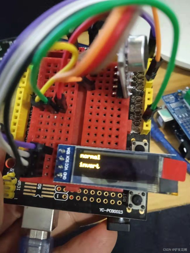
Arduino实验场景图
【Arduino】168种传感器模块系列实验(资料代码+仿真编程+图形编程)
实验一百三十六:0.91寸OLED液晶屏显示模块 IIC 12832液晶屏 兼容3.3v-5V
项目二十六:股票行情通过显示器上的一行字段移动文本(横向滚动)
实验开源代码
/*
【Arduino】168种传感器模块系列实验(资料代码+仿真编程+图形编程)
实验一百三十六:0.91寸OLED液晶屏显示模块 IIC 12832液晶屏 兼容3.3v-5V
项目二十六:股票行情通过显示器上的一行字段移动文本(横向滚动)
实验接线:
oled模块 Ardunio Uno
GND---------GND接地线
VCC---------5V 接电源
SDA---------A4
SCL ------- A5
*/
#define RTN_CHECK 1
#include
#include "SSD1306Ascii.h"
#include "SSD1306AsciiWire.h"
// 0X3C+SA0 - 0x3C or 0x3D
#define I2C_ADDRESS 0x3C
// Define proper RST_PIN if required.
#define RST_PIN -1
SSD1306AsciiWire oled;
// Ticker state. Maintains text pointer queue and current ticker state.
TickerState state;
// Use two strings to avoid modifying string being displayed.
String str[2];
//------------------------------------------------------------------------------
void setup() {
Wire.begin();
Wire.setClock(400000L);
#if RST_PIN >= 0
oled.begin(&Adafruit128x64, I2C_ADDRESS, RST_PIN);
#else // RST_PIN >= 0
oled.begin(&Adafruit128x64, I2C_ADDRESS);
#endif // RST_PIN >= 0
// Use Adafruit5x7, field at row 2, set2X, columns 16 through 100.
oled.tickerInit(&state, Adafruit5x7, 2, true, 16, 100);
}
uint16_t count;
uint32_t tickTime = 0;
void loop() {
if (tickTime <= millis()) {
tickTime = millis() + 30;
// Should check for error. rtn < 0 indicates error.
int8_t rtn = oled.tickerTick(&state);
// See above for definition of RTN_CHECK.
if (rtn <= RTN_CHECK) {
uint8_t pin = count%4;
// ping-pong string selection so displayed string is not modified.
uint8_t n = count%2;
str[n] = "ADC" + String(pin) + ": " + analogRead(pin) + ", ";
// Should check for error. Return of false indicates error.
oled.tickerText(&state, str[n]);
count++;
}
}
}
Arduino实验场景图