Packet Tracer - 实施基本连接
Packet Tracer - 实施基本连接
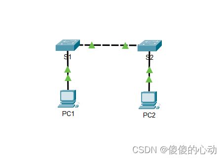
地址分配表
| 设备 |
接口 |
IP 地址 |
子网掩码 |
| S1 |
VLAN 1 |
192.168.1.253 |
255.255.255.0 |
| S2 |
VLAN 1 |
192.168.1.254 |
255.255.255.0 |
| PC1 |
网卡 |
192.168.1.1 |
255.255.255.0 |
| PC2 |
网卡 |
192.168.1.2 |
255.255.255.0 |
拓扑图
目标
第 1 部分:对 S1 和 S2 执行基本配置
第 2 部分:配置 PC
第 3 部分:配置交换机管理界面
背景信息
在本练习中,您将首先执行基本的交换机配置。然后您将通过在交换机和 PC 上配置 IP 编址来实施基本连接。当完成 IP 编址配置后,您将使用各种 show 命令来检验配置,并使用 ping 命令检验设备之间的基本连接。
第 1 部分:对 S1 和 S2 执行基本配置
在 S1 和 S2 上完成以下步骤。
第 1 步:为 S1 配置主机名。
- 单击 S1,然后单击 CLI 选项卡。
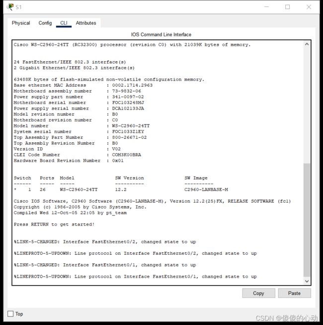
- 输入正确的命令,将主机名配置为 S1。
Switch>enable
Switch#conf t
Enter configuration commands, one per line. End with CNTL/Z.
Switch(config)#hostname S1
第 2 步:配置控制台和特权 EXEC 模式密码。
- 使用 cisco 作为控制台密码。
S1(config)#line console 0
S1(config-line)#password cisco
S1(config-line)#login
S1(config-line)#exit
- 使用 class 作为特权 EXEC 模式密码。
S1(config)#enable secret class
第 3 步:检验 S1 的密码配置。
如何检验两个密码都正确配置?
在退出用户 EXEC 模式后,交换机将提示您输入密码才能访问控制台接口,并在访问特权 EXEC 模式时再一次 提示您。您还可以使用 show run 命令查看密码。
第 4 步:配置 MOTD 标语。
使用适当的标语文本警告未经授权的访问。以下是示例文本:
Authorized access only. Violators will be prosecuted to the full extent of the law.
第 5 步:将配置文件保存到 NVRAM。
您使用哪个命令完成此步骤?
S1(config)# exit (or end)
S1# copy run start
第 6 步:为 S2 重复第 1 步到第 5 步。
Switch>enable
Switch#conf t
Enter configuration commands, one per line. End with CNTL/Z.
Switch(config)#hostname S2
S2(config)#line console 0
S2(config-line)#password cisco
S2(config-line)#login
S2(config-line)#exit
S2(config)#enable secret class
第 2 部分:配置 PC
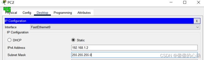
使用 IP 地址配置 PC1 和 PC2。
第 1 步:使用 IP 地址配置两台 PC。
a. 单击 PC1,然后单击 Desktop(桌面)选项卡。
b. 单击 IP Configuration(IP 配置)。在上面的地址分配表中,您会看到 PC1 的 IP 地址为 192.168.1.1,子网掩码为 255.255.255.0。在 IP Configuration(IP 配置)窗口中输入 PC1 的此信息。

- 对 PC2 重复第 1a 步和第 1b 步。
第 2 步:测试到交换机的连接。
a. 单击 PC1。如果 IP Configuration(IP 配置)窗口仍开着,关闭它。在 Desktop(桌面)选项卡中,单击 Command Prompt(命令提示符)。
b. 键入 ping 命令和 S1 的 IP 地址,然后按 Enter 键。
Packet Tracer PC Command Line 1.0
PC> ping 192.168.1.253
C:\>ping 192.168.1.253
Pinging 192.168.1.253 with 32 bytes of data:
Request timed out.
Request timed out.
Request timed out.
Request timed out.
Ping statistics for 192.168.1.253:
Packets: Sent = 4, Received = 0, Lost = 4 (100% loss),
C:\>
是否成功?说明原因。
您的 ping 操作应该不会成功,因为尚未给交换机配置 IP 地址。
第 3 部分:配置交换机管理界面
为 S1 和 S2 配置 IP 地址。
第 1 步:配置 S1 的 IP 地址。
交换机可用作即插即用设备。这意味着它们不需要配置就能工作。交换机根据 MAC 地址将来自一个端口的信息转发到另一个端口。若是如此,我们为什么要为其配置 IP 地址?
为了远程连接到交换机,需要给它分配一个 IP 地址。交换机的默认配置是通过 VLAN 1控制交换机的管理。
使用以下命令为 S1 配置 IP 地址。
S1# configure terminal
Enter configuration commands, one per line.End with CNTL/Z.
S1(config)# interface vlan 1
S1(config-if)# ip address 192.168.1.253 255.255.255.0
S1(config-if)# no shutdown
%LINEPROTO-5-UPDOWN: Line protocol on Interface Vlan1, changed state to up
S1(config-if)#
S1(config-if)# exit
S1#
您为什么需要输入 no shutdown 命令?
no shutdown 命令管理性地将该接口置于活动状态。
第 2 步:为 S2 配置 IP 地址。
使用地址分配表中的信息为 S2 配置 IP 地址。
S2(config)#interface vlan 1
S2(config-if)#ip address 192.168.1.254 255.255.255.0
S2(config-if)#no shutdown
S2(config-if)#
%LINK-5-CHANGED: Interface Vlan1, changed state to up
%LINEPROTO-5-UPDOWN: Line protocol on Interface Vlan1, changed state to up
S2(config-if)#end
S2#
%SYS-5-CONFIG_I: Configured from console by console
S2#
第 3 步:检验 S1 和 S2 上的 IP 地址配置。
使用 show ip interface brief 命令显示所有交换机端口和接口的 IP 地址和状态。也可使用 show running-config 命令。
S1#show ip interface brief
Interface IP-Address OK? Method Status Protocol
FastEthernet0/1 unassigned YES manual up up
FastEthernet0/2 unassigned YES manual up up
FastEthernet0/3 unassigned YES manual down down
FastEthernet0/4 unassigned YES manual down down
FastEthernet0/5 unassigned YES manual down down
FastEthernet0/6 unassigned YES manual down down
FastEthernet0/7 unassigned YES manual down down
FastEthernet0/8 unassigned YES manual down down
FastEthernet0/9 unassigned YES manual down down
FastEthernet0/10 unassigned YES manual down down
FastEthernet0/11 unassigned YES manual down down
FastEthernet0/12 unassigned YES manual down down
FastEthernet0/13 unassigned YES manual down down
FastEthernet0/14 unassigned YES manual down down
FastEthernet0/15 unassigned YES manual down down
FastEthernet0/16 unassigned YES manual down down
FastEthernet0/17 unassigned YES manual down down
FastEthernet0/18 unassigned YES manual down down
FastEthernet0/19 unassigned YES manual down down
FastEthernet0/20 unassigned YES manual down down
FastEthernet0/21 unassigned YES manual down down
FastEthernet0/22 unassigned YES manual down down
FastEthernet0/23 unassigned YES manual down down
FastEthernet0/24 unassigned YES manual down down
GigabitEthernet0/1 unassigned YES manual down down
GigabitEthernet0/2 unassigned YES manual down down
Vlan1 192.168.1.253 YES manual up up
S1#
S2#show ip interface brief
Interface IP-Address OK? Method Status Protocol
FastEthernet0/1 unassigned YES manual up up
FastEthernet0/2 unassigned YES manual up up
FastEthernet0/3 unassigned YES manual down down
FastEthernet0/4 unassigned YES manual down down
FastEthernet0/5 unassigned YES manual down down
FastEthernet0/6 unassigned YES manual down down
FastEthernet0/7 unassigned YES manual down down
FastEthernet0/8 unassigned YES manual down down
FastEthernet0/9 unassigned YES manual down down
FastEthernet0/10 unassigned YES manual down down
FastEthernet0/11 unassigned YES manual down down
FastEthernet0/12 unassigned YES manual down down
FastEthernet0/13 unassigned YES manual down down
FastEthernet0/14 unassigned YES manual down down
FastEthernet0/15 unassigned YES manual down down
FastEthernet0/16 unassigned YES manual down down
FastEthernet0/17 unassigned YES manual down down
FastEthernet0/18 unassigned YES manual down down
FastEthernet0/19 unassigned YES manual down down
FastEthernet0/20 unassigned YES manual down down
FastEthernet0/21 unassigned YES manual down down
FastEthernet0/22 unassigned YES manual down down
FastEthernet0/23 unassigned YES manual down down
FastEthernet0/24 unassigned YES manual down down
GigabitEthernet0/1 unassigned YES manual down down
GigabitEthernet0/2 unassigned YES manual down down
Vlan1 192.168.1.254 YES manual up up
S2#
第 4 步:将 S1 和 S2 的配置保存到 NVRAM。
哪条命令可用于将 RAM 中的配置文件保存到 NVRAM?
copy startup-config running-config
第 5 步:检验网络连接。
可使用 ping 命令检验网络连接。整个网络必须完全连通。如果存在任何故障,必须采取纠正措施。从 PC1 和 PC2 对 S1 和 S2 执行 ping 操作。
a. 单击 PC1,然后单击 Desktop(桌面)选项卡。
b. 单击 Command Prompt(命令提示符)。
c. 对 PC2 的 IP 地址执行 ping 操作。
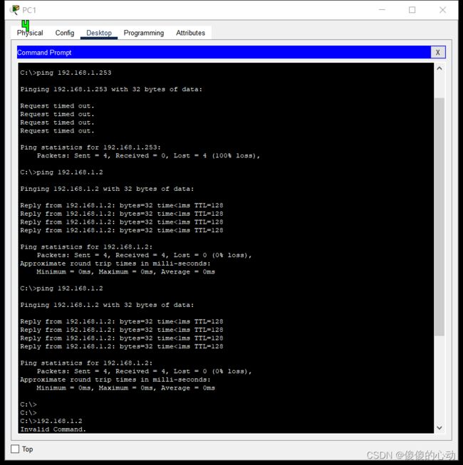
- 对 S1 的 IP 地址执行 ping 操作。
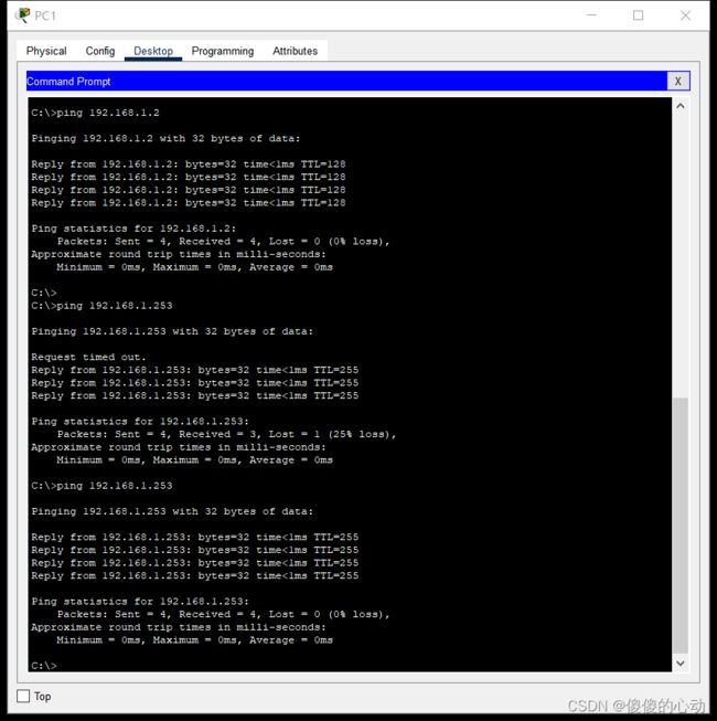
- 对 S2 的 IP 地址执行 ping 操作。
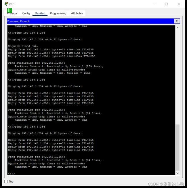
注意:您还可以在交换机 CLI 和 PC2 上使用 ping 命令。
所有 ping 都应该成功。如果您的第一次 ping 结果为 80%,请重试。现在应该为 100%。您将在稍后了解到为什么第一次 ping 有时可能发生故障。如果无法 ping 通任何设备,请重新检查您的配置,看看是否有错。
【实验链接】
链接:https://pan.baidu.com/s/12xYN7SmkLlV15Dke4rVj0A?pwd=5000
提取码:5000
--来自百度网盘超级会员V3的分享