ESP8266-OLED显示
安装驱动库
在之前的Arduino系列教程中,也有对OLED进行驱动的示例。这里我们依然使用「Adafruit_SSD1306」驱动库。
在Arduino IDE中点击「项目」—「加载库」—「管理库」,查找选择最新版本,点击安装,然后在弹出的对话框中选择Install all,安装全部的关联库。
arduinoIDE显示驱动的安装


PlatformIO库的下载的

硬件连接
这里使用IIC驱动屏,在IOT Kit开发板上,ESP8266的GPIO4(D2)和GPIO5(D1)分别通过跳线帽连接到OLED屏的SDA和SCL引脚。

编程下载
在Arduino IDE中新建sketch,拷贝如下代码并保存。
/*
* oled
* ESP8266驱动OLED屏
*/
#include 电脑连接开发板,在「工具」—「开发板」—「端口」中选择正确的端口号,点击上传,程序编译并上传。
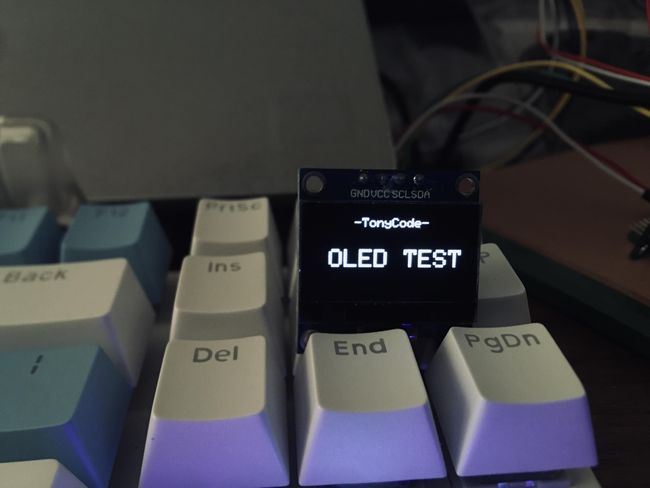
上传完成后,可以看到OLED可以显示了。
显示WiFi信息
在完成对OLED屏的驱动后,结合前篇连接网络的例程,我们就可以在OLED屏上查看连网信息了。
拷贝如下程序编译上传,之前在串口显示的连网信息就可以在OLED屏上显示了。
/*
 * oled_infor
 * OLED显示连网信息
 */

#include
#include
#include
#include

const char* ssid     = "your-ssid";//连接WIFI名(SSID)
const char* password = "your-password";//WIFI密码

Adafruit_SSD1306 oled(128, 64, &Wire, -1);

void setup()
{
  oled.begin(SSD1306_SWITCHCAPVCC,0x3C);
  oled.setTextColor(WHITE);//开像素点发光
  oled.clearDisplay();//清屏

  oled.setTextSize(1); //设置字体大小
  oled.setCursor(15, 5);//设置显示位置
  oled.println("WiFi Information");
  oled.setCursor(2, 20);//设置显示位置

  WiFi.begin(ssid,password);//启动网络连接

  while (WiFi.status() != WL_CONNECTED)//检测网络是否连接成功
  {
    delay(500);
    oled.print(".");//设置显示位置
    oled.display(); // 开显示
  }

  oled.setTextSize(1);//设置字体大小
  oled.setCursor(2, 35);//设置显示位置
  oled.println("Connected,IP address:");
  oled.println();
  oled.println(WiFi.localIP());
  oled.display(); // 开显示
}

void loop() {}
)
字模显示原理及取模软件的使用
我们使用的OLED屏是由方形的发光点阵列组成的,分辨率为128x64。英文和数字最小可用8x8像素,汉字最小显示像素为16x16,通常为了显示效果,英文和数字通常使用8x16像素表示。要显示需要的字符只需对应点亮像素区域中对应的发光点即可。
[外链图片转存中…(img-ee9qdcjj-1689498876692)]
字模一般都是通过取模软件生成的,接下来介绍「PCtoLCD」取模软件的使用:
Windows系统下双击启动软件,点击「模式」,选择「字符模式」,通常默认就是字符模式。

字符模式
点击「选项」进行字模配置。通常字模配置要根据程序驱动方式来选择,本篇中我们选择阴码、逐行式、顺向,其他选项如下图所示。

选项配置
输入汉字。点击生成字模或者保存字模,就会得到对应的点阵数据。
[外链图片转存中…(img-3OhcE2ug-1689498876694)]
生成字模
实验材料
- Uno R3开发板
- 配套USB数据线
- 面包板及配套连接线
- OLED显示屏
实验步骤
根据原理图搭建电路图。
IIC接口只需要两根线。OLED屏的VCC和GND分别连接开发板的3.3V和GND,OLED屏的SDA和SCL分别连接开发板A4和A5。
实验原理图如下图所示:
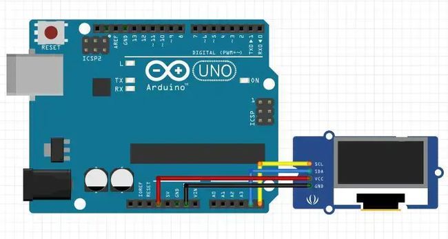
电路连接图
实物连接图如下图所示:
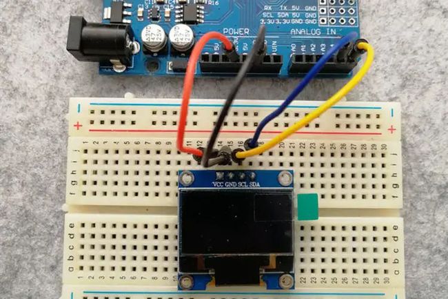
实物连接图
新建sketch,拷贝如下代码替换自动生成的代码并进行保存。
/*
  OLED显示汉字
*/
#include
#include
#include

#define OLED_RESET     4
Adafruit_SSD1306 display(128, 64, &Wire, OLED_RESET);

//取16X16汉字字模 逐行式 顺向高位在前
static const unsigned char PROGMEM str1[] =
{
  0x01, 0x00, 0x01, 0x00, 0x01, 0x00, 0x01, 0x00, 0x3F, 0xF8, 0x21, 0x08, 0x21, 0x08, 0x21, 0x08,
  0x21, 0x08, 0x21, 0x08, 0x3F, 0xF8, 0x21, 0x08, 0x01, 0x00, 0x01, 0x00, 0x01, 0x00, 0x01, 0x00
};/*"中",0*/

static const unsigned char PROGMEM str2[] =
{
  0x02, 0x00, 0x01, 0x00, 0x01, 0x00, 0xFF, 0xFE, 0x10, 0x10, 0x10, 0x10, 0x08, 0x20, 0x08, 0x20,
  0x04, 0x40, 0x02, 0x80, 0x01, 0x00, 0x02, 0x80, 0x04, 0x40, 0x08, 0x20, 0x30, 0x18, 0xC0, 0x06
};/*"文",1*/
static const unsigned char PROGMEM str3[] =
{
  0x00, 0x00, 0x1F, 0xF0, 0x10, 0x10, 0x10, 0x10, 0x1F, 0xF0, 0x10, 0x10, 0x10, 0x10, 0x1F, 0xF0,
  0x04, 0x40, 0x44, 0x44, 0x24, 0x44, 0x14, 0x48, 0x14, 0x50, 0x04, 0x40, 0xFF, 0xFE, 0x00, 0x00
};/*"显",2*/

static const unsigned char PROGMEM str4[] =
{
  0x00, 0x00, 0x3F, 0xF8, 0x00, 0x00, 0x00, 0x00, 0x00, 0x00, 0x00, 0x00, 0xFF, 0xFE, 0x01, 0x00,
  0x01, 0x00, 0x11, 0x10, 0x11, 0x08, 0x21, 0x04, 0x41, 0x02, 0x81, 0x02, 0x05, 0x00, 0x02, 0x00
};/*"示",3*/

void setup() {
  display.begin(SSD1306_SWITCHCAPVCC, 0x3C);
  display.setTextColor(WHITE);//开像素点发光
  display.clearDisplay();//清屏

  display.setTextSize(1); //设置字体大小
  display.setCursor(35, 5);//设置显示位置
  display.println("-TonyCode-");//输出字符

  display.drawBitmap(32, 32, str1, 16, 16, 1); //画出字符对应点阵数据
  display.drawBitmap(48, 32, str2, 16, 16, 1); //画出字符对应点阵数据
  display.drawBitmap(64, 32, str3, 16, 16, 1); //画出字符对应点阵数据
  display.drawBitmap(80, 32, str4, 16, 16, 1); //画出字符对应点阵数据
  display.display();//开显示

}

void loop() {

}
连接开发板,设置好对应端口号和开发板类型,进行程序下载。
[外链图片转存中…(img-SCIl5amr-1689498876696)]
程序下载
实验现象
OLED显示出对应中文。

实验分析
程序中我们使用了图像库「Adafruit_GFX」中的drawBitmap()函数,函数参数分别输入了要显示的坐标,字符数据源,字符的宽高,最后参数由于我们的OLED是单色的,默认为1。
我们可以选择不同的字体,也可以使用不同像素获取不同大小的字符,如下图显示的是32x32像素的汉字,注意drawBitmap()函数中对应字符宽高需要对应。
