- 什么是证书吊销列表?CRL 解释
WoTrusSSL
sslhttps
数字证书是安全在线互动的支柱,用于验证身份和确保加密通信。但是,当这些证书被盗用或滥用时,必须立即撤销它们以维持信任。这就是证书撤销列表(CRL)的作用所在。CRL由证书颁发机构(CA)维护,对于识别和撤销已撤销的证书,防止其造成危害至关重要。在本指南中,我们将探讨什么是CRL、它们如何运作以及为什么它们对网络安全至关重要。什么是证书吊销列表(CRL)?证书吊销列表(CRL)是证书颁发机构(CA)
- k8s:安装 Helm 私有仓库ChartMuseum、helm-push插件并上传、安装Zookeeper
云游
dockerhelmhelm-push
ChartMuseum是Kubernetes生态中用于存储、管理和发布HelmCharts的开源系统,主要用于扩展Helm包管理器的功能核心功能集中存储:提供中央化仓库存储Charts,支持版本管理和权限控制。跨集群部署:支持多集群环境下共享Charts,简化部署流程。离线部署:适配无网络环境,可将Charts存储在本地或局域网内。HTTP接口:通过HTTP协议提供服务,用户
- 【LeetCode 热题 100】24. 两两交换链表中的节点——(解法一)迭代+哨兵
xumistore
LeetCodeleetcode链表算法java
Problem:24.两两交换链表中的节点题目:给你一个链表,两两交换其中相邻的节点,并返回交换后链表的头节点。你必须在不修改节点内部的值的情况下完成本题(即,只能进行节点交换)。文章目录整体思路完整代码时空复杂度时间复杂度:O(N)空间复杂度:O(1)整体思路这段代码旨在解决一个经典的链表操作问题:两两交换链表中的节点(SwapNodesinPairs)。问题要求将链表中每两个相邻的节点进行交换
- Android 开源组件和第三方库汇总
gyyzzr
AndroidAndroid开源框架
转载1、github排名https://github.com/trending,github搜索:https://github.com/search2、https://github.com/wasabeef/awesome-android-ui目录UIUI卫星菜单节选器下拉刷新模糊效果HUD与Toast进度条UI其它动画网络相关响应式编程地图数据库图像浏览及处理视频音频处理测试及调试动态更新热更新
- ARM嵌入式可编程控制器技术开发
拉勾科研工作室
arm开发
PLC自动化设计|毕业设计指导|工业自动化解决方案✨专业领域:PLC程序设计与调试工业自动化控制系统HMI人机界面开发工业传感器应用电气控制系统设计工业网络通信擅长工具:西门子S7系列PLC编程三菱/欧姆龙PLC应用触摸屏界面设计电气CAD制图工业现场总线技术自动化设备调试主要内容:PLC控制系统设计工业自动化方案规划电气原理图绘制控制程序编写与调试毕业论文指导毕业设计题目与程序设计✅具体问题可以
- 理解TCP连接中的进程阻塞与CPU调度机制
109702008
编程#C语言网络tcp/ip网络人工智能
引言在计算机网络通信中,TCP连接的建立是一个经典的三次握手过程。当用户调用connect()函数发起连接时,内核会发送SYN报文并等待对方的SYN-ACK响应。此时,调用进程通常会进入阻塞状态,暂停执行直至连接成功或超时。这一机制看似简单,但其背后的内核实现却涉及进程调度、等待队列管理和CPU资源分配等复杂操作。本文将深入探讨阻塞状态的实现原理,并解析CPU在进程阻塞期间的行为。一、进程阻塞的实
- php SPOF
贵哥的编程之路(热爱分享 为后来者)
PHP语言经典程序100题php开发语言
1.什么是单点故障(SPOF)?单点故障指的是系统中某个组件一旦失效,整个系统或服务就会不可用。常见的单点有:数据库、缓存、Web服务器、负载均衡、网络设备等。2.常见单点故障场景只有一台数据库服务器,宕机后所有业务不可用只有一台Redis缓存,挂掉后缓存全部失效只有一台Web服务器,挂掉后网站无法访问只有一个负载均衡节点,挂掉后流量无法分发只有一条网络链路,断开后所有服务失联3.消除单点故障的主
- 计算机网络技术
CZZDg
计算机网络
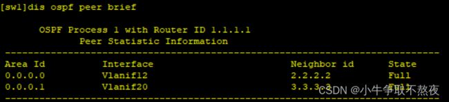
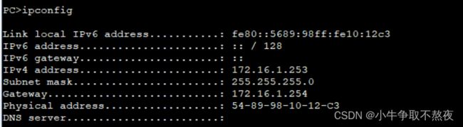
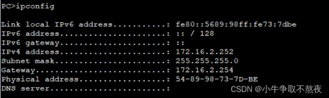
目录一.网络概述1.网络的概念2.网络发展是3.网络的四要素4.网络功能5.网络类型6.网络协议与标准7.网络中常见的概念8.网络拓补结构二.网络模型1.分层思想2.OSI七层模型3.TCP/IP五层模型4.数据的封装与解封装过程三.IP地址1.进制转换2.IP地址定义3.IP地址组成成分4.IP地址分类5.地址划分6、相关概念一.网络概述1.网络的概念两个主机通过传输介质和通信协议实现通信和资源
- 玩转Docker | 使用Docker部署gopeed下载工具
心随_风动
玩转Dockerdocker容器运维
玩转Docker|使用Docker部署gopeed下载工具前言一、gopeed介绍Gopeed简介主要特点二、系统要求环境要求环境检查Docker版本检查检查操作系统版本三、部署gopeed服务下载镜像创建容器检查容器状态检查服务端口安全设置四、访问gopeed应用五、测试与下载六、总结前言在当今信息爆炸的时代,高效地获取和管理网络资源变得尤为重要。无论是下载大型文件还是进行日常的数据传输,一个稳
- Docker指定网桥和指定网桥IP
$dockernetworklsNETWORKIDNAMEDRIVER7fca4eb8c647bridgebridge9f904ee27bf5nonenullcf03ee007fb4hosthostBridge默认bridge网络,我们可以使用dockernetworkinspect命令查看返回的网络信息,我们使用dockerrun命令是将网络自动应用到新的容器Host如果是hosts模式,启动容
- UNIX域套接字
1、UNIX域套接字的定义UNIX域套接字是进程间通信(IPC)的一种方式,不涉及网络协议栈,因此在同一台主机上的通信中,它比基于TCP/IP协议的网络套接字更快速、更高效。2、UNIX域套接字的分类字节流套接字(SOCK_STREAM):提供面向连接的、可靠的数据传输服务。数据报套接字(SOCK_DGRAM):提供无连接的数据传输服务,数据以独立的数据报形式传输。3、UNIX套接字与TCP/IP
- Kimi Chat 1.5 与 2.0 架构升级对比
charles666666
人工智能transformer深度学习产品经理chatgpt
1.5版的MoE架构优化KimiChat1.5采用了优化后的MoE架构,其核心在于“专家网络动态路由”。这一机制类似于快递系统智能选择最优路径,能够根据输入数据的特性动态分配计算资源。这种优化显著提升了模型的计算效率,同时降低了硬件资源的浪费。在实际应用中,这意味着开发者可以在相同的硬件配置下处理更复杂的任务,或者在有限的资源下实现更高的性能。2.0的混合专家系统创新点与1.5版相比,KimiCh
- 什么是OA系统?使用OA系统对企业有哪些好处?
OA系统(OfficeAutomationSystem),即办公自动化系统,是将现代化办公和计算机网络功能结合起来的一种新型的办公方式。是现代企业管理中一种重要的信息化工具,它通过计算机技术、网络技术和数据库技术等手段,实现企业内部办公流程的自动化和信息化管理。使企业的信息交流更加顺畅,办公流程更加高效,从而提高企业的运营效率和管理水平。一、主要功能1.文档管理文档存储与检索:OA系统可以集中存储
- Docker容器底层原理详解:从零理解容器化技术
Debug Your Career
面试docker容器dockerjava
一、容器本质:一个“隔离的进程”关键认知:Docker容器并不是一个完整的操作系统,而是一个被严格隔离的进程。这个进程拥有独立的文件系统、网络、进程视图等资源,但它直接运行在宿主机内核上(而虚拟机需要模拟硬件和操作系统)。类比理解:想象你在一个办公楼里租了一间独立办公室(容器)。你有自己的桌椅(文件系统)、电话分机(网络)、门牌号(主机名),但共享整栋楼的水电(宿主机内核)和电梯(硬件资源)。办公
- .NET 一款基于BGInfo的红队内网渗透工具
dot.Net安全矩阵
网络.net安全.netcoreweb安全矩阵
01阅读须知此文所提供的信息只为网络安全人员对自己所负责的网站、服务器等(包括但不限于)进行检测或维护参考,未经授权请勿利用文章中的技术资料对任何计算机系统进行入侵操作。利用此文所提供的信息而造成的直接或间接后果和损失,均由使用者本人负责。本文所提供的工具仅用于学习,禁止用于其他方面02基本介绍在内网渗透过程中,白名单绕过是红队常见的技术需求。Sharp4Bginfo.exe是一款基于微软签名工具
- 如何发现 Redis 中的 BigKey?
sevevty-seven
redisbootstrap数据库
如何发现Redis中的BigKey?Redis因其出色的性能,常被用作缓存、消息队列和会话存储。然而,在Redis的使用过程中,BigKey是一个不容忽视的问题。BigKey指的是存储了大量数据或包含大量成员的键。它们不仅会占用大量内存,还可能导致网络延迟、主从同步延迟,甚至在极端情况下引发Redis服务崩溃。因此,有效地发现和处理BigKey对于维护Redis服务的稳定性和性能至关重要。本文将深
- 11. TCP 滑动窗口、拥塞控制是什么,有什么区别
yqcoder
前端面试-服务协议tcp/ip网络php
总结滑动窗口:早期网络,通信双方不考虑网络拥挤情况,导致掉包。滑动窗口大小意味着有多少缓冲区接受数据。拥塞控制:防止过多数据注入网络中,拥塞控制是一个全局过程,控制网络流量。区别:滑动窗口解决掉包问题,拥塞控制解决网络拥塞问题。TCP滑动窗口与拥塞控制详解在TCP协议中,为了实现可靠传输和高效通信,引入了两个核心机制:滑动窗口(SlidingWindow)和拥塞控制(CongestionContr
- 上位机知识篇---Linux中的文件挂载
Atticus-Orion
上位机操作篇linux运维网络文件挂载
文章目录前言1.挂载的基本概念文件系统挂载点设备文件2.挂载的命令挂载文件系统示例卸载文件系统示例3.挂载的常用选项示例4.自动挂载(/etc/fstab文件)示例使用UUID挂载5.挂载网络文件系统(NFS)挂载NFS示例6.挂载ISO文件挂载ISO文件示例7.查看已挂载的文件系统8.挂载的注意事项9.挂载的常见问题挂载失败卸载失败10.总结前言在Linux系统中,文件挂载是指将一个文件系统(如
- 深度学习篇---昇腾NPU&CANN 工具包
Atticus-Orion
上位机知识篇图像处理篇深度学习篇深度学习人工智能NPU昇腾CANN
介绍昇腾NPU是华为推出的神经网络处理器,具有强大的AI计算能力,而CANN工具包则是面向AI场景的异构计算架构,用于发挥昇腾NPU的性能优势。以下是详细介绍:昇腾NPU架构设计:采用达芬奇架构,是一个片上系统,主要由特制的计算单元、大容量的存储单元和相应的控制单元组成。集成了多个CPU核心,包括控制CPU和AICPU,前者用于控制处理器整体运行,后者承担非矩阵类复杂计算。此外,还拥有AICore
- 计算机科学与技术
柳依依@
学习前端c4前端后端
计算机科学是一个庞大且关联性强的学科体系,初学者常面临以下痛点:-**知识点零散**:容易陷入"只见树木不见森林"的学习困境-**方向不明确**:面对海量技术栈不知从何入手-**体系缺失**:难以建立完整的知识网络1.计算机基础-计算机组成原理-冯·诺依曼体系-CPU/内存/IO设备-操作系统-进程与线程-内存管理-文件系统-计算机网络-TCP/IP模型-HTTP/HTTPS-网络安全2.编程能力
- Ubuntu 服务器虚拟主机,ubuntu云服务器虚拟机
Gamer42
Ubuntu服务器虚拟主机
ubuntu云服务器虚拟机内容精选换一换通过云服务器或者外部镜像文件创建私有镜像时,如果云服务器或镜像文件所在虚拟机的网络配置是静态IP地址时,您需要修改网卡属性为DHCP,以使私有镜像发放的新云服务器可以动态获取IP地址。本节以WindowsServer2008R2操作系统为例。其他操作系统配置方法略有区别,请参考对应操作系统的相关资料进行操作,文档中不对此进行详细说明后端虚拟机绑定EIP。登录
- 深度学习图像分类数据集—桃子识别分类
AI街潜水的八角
深度学习图像数据集深度学习分类人工智能
该数据集为图像分类数据集,适用于ResNet、VGG等卷积神经网络,SENet、CBAM等注意力机制相关算法,VisionTransformer等Transformer相关算法。数据集信息介绍:桃子识别分类:['B1','M2','R0','S3']训练数据集总共有6637张图片,每个文件夹单独放一种数据各子文件夹图片统计:·B1:1601张图片·M2:1800张图片·R0:1601张图片·S3:
- ModBus总线协议
小仇学长
STM32网络Modbus协议
一、知识点1.什么是Modbus协议?Modbus是一种工业通信协议,最早由Modicon公司在1979年提出,目的是用于PLC(可编程逻辑控制器)之间的数据通信。它是主从式通信,即一个主机(主设备)控制一个或多个从机(从设备)。它常用于RS-232、RS-485串口通信,也可以用于TCP/IP网络通信(叫做ModbusTCP)。2.核心特征特征项内容通信结构主从式(Master/Slave)通信
- 2.4 基于dpdk的用户态协议栈的实现
百亿苍狗
高性能网络设计专栏开发语言网络
操作系统PosixAPI所提供的网络接口,数据收发是基于用户态与内核态的频繁切换实现。而dpdk实现了绕过内核监管,直接在用户态访问网络硬件,避免频繁状态切换。DPDK安装与配置虚拟机环境配置检查是否支持多队列网卡cat/proc/interrupts|grepens33(获取整个机器的终端),结果19:4202120IO-APIC19-fasteoiens33,不支持多队列网卡。虚拟机关机,修改
- 使用NVIDIA NeRF将2D图像转换为逼真的3D模型(Python)
ByteWhiz
3dpython计算机视觉Python
使用NVIDIANeRF将2D图像转换为逼真的3D模型(Python)NeuralRadianceFields(NeRF)是一种强大的方法,可以将2D图像转换为逼真的3D模型。它使用神经网络来建模场景的辐射场,并通过渲染多个视角的图像来重建3D模型。在本文中,我们将使用Python和NVIDIANeRF库来实现这一过程。首先,我们需要安装所需的库。我们可以通过以下命令使用pip安装NVIDIANe
- TCP和UDP协议区别+应用场景+优缺点+常用协议
马拉萨的春天
一天一读基础知识点tcp/ipudp网络
文章目录1.TCP协议特点应用场景优点缺点运行于TCP协议之上的协议2.UDP协议特点应用场景优点缺点运行于UDP协议之上的协议TCP(TransmissionControlProtocol)和UDP(UserDatagramProtocol)是两种常用的传输层协议,它们在网络通信中扮演不同的角色,各有优缺点。1.TCP协议特点提供面向连接的、可靠的数据传输服务。使用三次握手建立连接,四次挥手断开
- C语言手写一个简易 DNS 客户端
(Charon)
服务器linux网络
本文聚焦讲解如何通过C语言构造并发送一个最小化的DNS请求,特别以dns_client_commit()函数为主线,带你一步步理解DNS请求的构造过程。为什么要学习DNS报文构造?我们平时在浏览器里输入一个网址(比如www.baidu.com),浏览器其实背后会通过操作系统的DNS模块发送一个查询请求,将域名解析为IP地址。而如果我们手动用C语言自己构造DNS请求,我们可以更深刻地理解底层网络通信
- 服务器或网络卡的原因和状况
qq2453939845
服务器网络网络服务器
卡的情况下,请先检查您服务器的使用情况。1、CPU使用率是否大于50%。2、内存使用率是否过高。3、网络使用率是否过高。如您购买的是10mbps,那么您服务器的网卡如果为100mbps的连接速率,当网络使用率为10%左右的情况下,则表示您的服务器带宽跑满了,以此类推,如果是千兆网卡(连接速率1000mbps)的,则显示1%即为10mbps。如果出现上述情况,则表明您的服务器或网络无法承载您目前的服
- 8个Java TCP/UDP框架:优缺点及应用场景全解析!
技术男老张
#编程语言-JAVA编程语言javatcp/ipudpssl网络协议websockethttp
JavaTCP框架在现代网络编程中扮演着至关重要的角色,尤其是在需要高效、稳定且可扩展的网络通信解决方案时。本文将深入探讨一些主流的JavaTCP/UDP框架,分析它们的优缺点以及适用场景,旨在为开发者提供一份详尽的指南。一、NettyNetty是一个异步事件驱动的网络应用框架,用于快速开发高性能、高可靠性的网络IO程序。Netty的设计目标是简化网络编程的复杂性,同时提高网络应用的性能和可扩展性
- 基于TCP/UDP的应用层协议
huangxy10
面试专题——网络知识
1,基于TCP的有:Telnet(TeletypeovertheNetwork,网络电传),通过一个终端(terminal)登陆到网络
- [黑洞与暗粒子]没有光的世界
comsci
无论是相对论还是其它现代物理学,都显然有个缺陷,那就是必须有光才能够计算
但是,我相信,在我们的世界和宇宙平面中,肯定存在没有光的世界....
那么,在没有光的世界,光子和其它粒子的规律无法被应用和考察,那么以光速为核心的
&nbs
- jQuery Lazy Load 图片延迟加载
aijuans
jquery
基于 jQuery 的图片延迟加载插件,在用户滚动页面到图片之后才进行加载。
对于有较多的图片的网页,使用图片延迟加载,能有效的提高页面加载速度。
版本:
jQuery v1.4.4+
jQuery Lazy Load v1.7.2
注意事项:
需要真正实现图片延迟加载,必须将真实图片地址写在 data-original 属性中。若 src
- 使用Jodd的优点
Kai_Ge
jodd
1. 简化和统一 controller ,抛弃 extends SimpleFormController ,统一使用 implements Controller 的方式。
2. 简化 JSP 页面的 bind, 不需要一个字段一个字段的绑定。
3. 对 bean 没有任何要求,可以使用任意的 bean 做为 formBean。
使用方法简介
- jpa Query转hibernate Query
120153216
Hibernate
public List<Map> getMapList(String hql,
Map map) {
org.hibernate.Query jpaQuery = entityManager.createQuery(hql);
if (null != map) {
for (String parameter : map.keySet()) {
jp
- Django_Python3添加MySQL/MariaDB支持
2002wmj
mariaDB
现状
首先,
[email protected] 中默认的引擎为 django.db.backends.mysql 。但是在Python3中如果这样写的话,会发现 django.db.backends.mysql 依赖 MySQLdb[5] ,而 MySQLdb 又不兼容 Python3 于是要找一种新的方式来继续使用MySQL。 MySQL官方的方案
首先据MySQL文档[3]说,自从MySQL
- 在SQLSERVER中查找消耗IO最多的SQL
357029540
SQL Server
返回做IO数目最多的50条语句以及它们的执行计划。
select top 50
(total_logical_reads/execution_count) as avg_logical_reads,
(total_logical_writes/execution_count) as avg_logical_writes,
(tot
- spring UnChecked 异常 官方定义!
7454103
spring
如果你接触过spring的 事物管理!那么你必须明白 spring的 非捕获异常! 即 unchecked 异常! 因为 spring 默认这类异常事物自动回滚!!
public static boolean isCheckedException(Throwable ex)
{
return !(ex instanceof RuntimeExcep
- mongoDB 入门指南、示例
adminjun
javamongodb操作
一、准备工作
1、 下载mongoDB
下载地址:http://www.mongodb.org/downloads
选择合适你的版本
相关文档:http://www.mongodb.org/display/DOCS/Tutorial
2、 安装mongoDB
A、 不解压模式:
将下载下来的mongoDB-xxx.zip打开,找到bin目录,运行mongod.exe就可以启动服务,默
- CUDA 5 Release Candidate Now Available
aijuans
CUDA
The CUDA 5 Release Candidate is now available at http://developer.nvidia.com/<wbr></wbr>cuda/cuda-pre-production. Now applicable to a broader set of algorithms, CUDA 5 has advanced fe
- Essential Studio for WinRT网格控件测评
Axiba
JavaScripthtml5
Essential Studio for WinRT界面控件包含了商业平板应用程序开发中所需的所有控件,如市场上运行速度最快的grid 和chart、地图、RDL报表查看器、丰富的文本查看器及图表等等。同时,该控件还包含了一组独特的库,用于从WinRT应用程序中生成Excel、Word以及PDF格式的文件。此文将对其另外一个强大的控件——网格控件进行专门的测评详述。
网格控件功能
1、
- java 获取windows系统安装的证书或证书链
bewithme
windows
有时需要获取windows系统安装的证书或证书链,比如说你要通过证书来创建java的密钥库 。
有关证书链的解释可以查看此处 。
public static void main(String[] args) {
SunMSCAPI providerMSCAPI = new SunMSCAPI();
S
- NoSQL数据库之Redis数据库管理(set类型和zset类型)
bijian1013
redis数据库NoSQL
4.sets类型
Set是集合,它是string类型的无序集合。set是通过hash table实现的,添加、删除和查找的复杂度都是O(1)。对集合我们可以取并集、交集、差集。通过这些操作我们可以实现sns中的好友推荐和blog的tag功能。
sadd:向名称为key的set中添加元
- 异常捕获何时用Exception,何时用Throwable
bingyingao
用Exception的情况
try {
//可能发生空指针、数组溢出等异常
} catch (Exception e) {
- 【Kafka四】Kakfa伪分布式安装
bit1129
kafka
在http://bit1129.iteye.com/blog/2174791一文中,实现了单Kafka服务器的安装,在Kafka中,每个Kafka服务器称为一个broker。本文简单介绍下,在单机环境下Kafka的伪分布式安装和测试验证 1. 安装步骤
Kafka伪分布式安装的思路跟Zookeeper的伪分布式安装思路完全一样,不过比Zookeeper稍微简单些(不
- Project Euler
bookjovi
haskell
Project Euler是个数学问题求解网站,网站设计的很有意思,有很多problem,在未提交正确答案前不能查看problem的overview,也不能查看关于problem的discussion thread,只能看到现在problem已经被多少人解决了,人数越多往往代表问题越容易。
看看problem 1吧:
Add all the natural num
- Java-Collections Framework学习与总结-ArrayDeque
BrokenDreams
Collections
表、栈和队列是三种基本的数据结构,前面总结的ArrayList和LinkedList可以作为任意一种数据结构来使用,当然由于实现方式的不同,操作的效率也会不同。
这篇要看一下java.util.ArrayDeque。从命名上看
- 读《研磨设计模式》-代码笔记-装饰模式-Decorator
bylijinnan
java设计模式
声明: 本文只为方便我个人查阅和理解,详细的分析以及源代码请移步 原作者的博客http://chjavach.iteye.com/
import java.io.BufferedOutputStream;
import java.io.DataOutputStream;
import java.io.FileOutputStream;
import java.io.Fi
- Maven学习(一)
chenyu19891124
Maven私服
学习一门技术和工具总得花费一段时间,5月底6月初自己学习了一些工具,maven+Hudson+nexus的搭建,对于maven以前只是听说,顺便再自己的电脑上搭建了一个maven环境,但是完全不了解maven这一强大的构建工具,还有ant也是一个构建工具,但ant就没有maven那么的简单方便,其实简单点说maven是一个运用命令行就能完成构建,测试,打包,发布一系列功
- [原创]JWFD工作流引擎设计----节点匹配搜索算法(用于初步解决条件异步汇聚问题) 补充
comsci
算法工作PHP搜索引擎嵌入式
本文主要介绍在JWFD工作流引擎设计中遇到的一个实际问题的解决方案,请参考我的博文"带条件选择的并行汇聚路由问题"中图例A2描述的情况(http://comsci.iteye.com/blog/339756),我现在把我对图例A2的一个解决方案公布出来,请大家多指点
节点匹配搜索算法(用于解决标准对称流程图条件汇聚点运行控制参数的算法)
需要解决的问题:已知分支
- Linux中用shell获取昨天、明天或多天前的日期
daizj
linuxshell上几年昨天获取上几个月
在Linux中可以通过date命令获取昨天、明天、上个月、下个月、上一年和下一年
# 获取昨天
date -d 'yesterday' # 或 date -d 'last day'
# 获取明天
date -d 'tomorrow' # 或 date -d 'next day'
# 获取上个月
date -d 'last month'
#
- 我所理解的云计算
dongwei_6688
云计算
在刚开始接触到一个概念时,人们往往都会去探寻这个概念的含义,以达到对其有一个感性的认知,在Wikipedia上关于“云计算”是这么定义的,它说:
Cloud computing is a phrase used to describe a variety of computing co
- YII CMenu配置
dcj3sjt126com
yii
Adding id and class names to CMenu
We use the id and htmlOptions to accomplish this. Watch.
//in your view
$this->widget('zii.widgets.CMenu', array(
'id'=>'myMenu',
'items'=>$this-&g
- 设计模式之静态代理与动态代理
come_for_dream
设计模式
静态代理与动态代理
代理模式是java开发中用到的相对比较多的设计模式,其中的思想就是主业务和相关业务分离。所谓的代理设计就是指由一个代理主题来操作真实主题,真实主题执行具体的业务操作,而代理主题负责其他相关业务的处理。比如我们在进行删除操作的时候需要检验一下用户是否登陆,我们可以删除看成主业务,而把检验用户是否登陆看成其相关业务
- 【转】理解Javascript 系列
gcc2ge
JavaScript
理解Javascript_13_执行模型详解
摘要: 在《理解Javascript_12_执行模型浅析》一文中,我们初步的了解了执行上下文与作用域的概念,那么这一篇将深入分析执行上下文的构建过程,了解执行上下文、函数对象、作用域三者之间的关系。函数执行环境简单的代码:当调用say方法时,第一步是创建其执行环境,在创建执行环境的过程中,会按照定义的先后顺序完成一系列操作:1.首先会创建一个
- Subsets II
hcx2013
set
Given a collection of integers that might contain duplicates, nums, return all possible subsets.
Note:
Elements in a subset must be in non-descending order.
The solution set must not conta
- Spring4.1新特性——Spring缓存框架增强
jinnianshilongnian
spring4
目录
Spring4.1新特性——综述
Spring4.1新特性——Spring核心部分及其他
Spring4.1新特性——Spring缓存框架增强
Spring4.1新特性——异步调用和事件机制的异常处理
Spring4.1新特性——数据库集成测试脚本初始化
Spring4.1新特性——Spring MVC增强
Spring4.1新特性——页面自动化测试框架Spring MVC T
- shell嵌套expect执行命令
liyonghui160com
一直都想把expect的操作写到bash脚本里,这样就不用我再写两个脚本来执行了,搞了一下午终于有点小成就,给大家看看吧.
系统:centos 5.x
1.先安装expect
yum -y install expect
2.脚本内容:
cat auto_svn.sh
#!/bin/bash
- Linux实用命令整理
pda158
linux
0. 基本命令 linux 基本命令整理
1. 压缩 解压 tar -zcvf a.tar.gz a #把a压缩成a.tar.gz tar -zxvf a.tar.gz #把a.tar.gz解压成a
2. vim小结 2.1 vim替换 :m,ns/word_1/word_2/gc
- 独立开发人员通向成功的29个小贴士
shoothao
独立开发
概述:本文收集了关于独立开发人员通向成功需要注意的一些东西,对于具体的每个贴士的注解有兴趣的朋友可以查看下面标注的原文地址。
明白你从事独立开发的原因和目的。
保持坚持制定计划的好习惯。
万事开头难,第一份订单是关键。
培养多元化业务技能。
提供卓越的服务和品质。
谨小慎微。
营销是必备技能。
学会组织,有条理的工作才是最有效率的。
“独立
- JAVA中堆栈和内存分配原理
uule
java
1、栈、堆
1.寄存器:最快的存储区, 由编译器根据需求进行分配,我们在程序中无法控制.2. 栈:存放基本类型的变量数据和对象的引用,但对象本身不存放在栈中,而是存放在堆(new 出来的对象)或者常量池中(字符串常量对象存放在常量池中。)3. 堆:存放所有new出来的对象。4. 静态域:存放静态成员(static定义的)5. 常量池:存放字符串常量和基本类型常量(public static f