Robust Dynamic Indoor Visible Light Positioning Method Based on CMOS Image Sensor
- Senzhen Sun, Guangyun Li, Yangjun Gao, et al.Robust Dynamic Indoor Visible Light Positioning Method Based on CMOS Image Sensor[J].Photogrammetric Engineering & Remote Sensing.2022,88(5): 333–342.
Robust Dynamic Indoor Visible Light Positioning Method Based on CMOS Image Sensor
Senzhen Sun 1, Guangyun Li1, * Yangjun Gao 1,2 and Li Wang1,2
Abstract: A real-time imaging recognition and positioning method based on visible light communication flat light source is proposed. This method images the visible light communication flat light source through the rolling shutter effect of the Complementary Metal-Oxide Semiconductor(CMOS) imaging sensor, and obtains the rectangular area outline of the light source and the light and dark stripe information of image with the digital image processing method, realizes light source matching recognition by defining the concept, the autocorrelation sequence, which can be used to obtain the ID of light source and the rectangular vertex coordinate information of flat light source, achieves high precision vision positioning on the basis of inertial measurement unit(IMU) attitude sensor-assisted imaging. Simultaneously, the corresponding positioning module is developed for positioning testing. The test results indicate that the plane positioning error is less than 4.5cm, and the positioning frequency is greater than 10Hz, which provides a high-precision visual positioning solution for indoor positioning.
Keywords: visible light communication; rolling shutter, visual imaging; signal matching; indoor positioning
1. Introduction
With the development of urbanization, the demand for indoor positioning technology is increasing in areas such as large building venues, automated factories, underground spaces and so on. The global satellite navigation system can basically meet the navigation and positioning requirements in most outdoor areas, but it cannot work indoors because of the difficulty in receiving satellite signals. Therefore, base station wireless indoor positioning technologies based on Wi-Fi, Bluetooth, ultra-wide band (UWB), pseudo satellite, radio frequency and so on came into being [1]. However, the indoor structure is diverse and the electromagnetic environment is complex. Taking the UWB base station type wireless indoor positioning solution as an example, it needs to set additional positioning base stations, dedicated receiving equipment, special data processing center, and dedicated personnel maintenance. This kind of base station wireless indoor positioning technology requires a balance between positioning accuracy and operation cost and its versatility is poor. With the development of deep learning technology, indoor positioning methods based on multi-sensor fusion technologies such as semantic simultaneous localization and mapping (SLAM) have made great progress [2], but the engineering application of large-scale SLAM technology is difficult to adapt to dynamic application scenarios [3], and absolute position calibration is required. With the widely application of the light-emitting diode (LED) lighting system, the indoor positioning technology based on visible light communication technology shows a broad application prospect. For example, the visible light positioning (VLP) system based on imaging has less changes to the environment, takes both lighting and positioning into account, and has the advantages of high positioning accuracy, low system cost and no electromagnetic interference [4], and is very suitable for mobile robot position calibration.
The implementation models of indoor visible light communication positioning technologies are mainly divided into imaging method and non-imaging method according to the types of receivers. The non-imaging positioning method of visible light communication mainly utilizes the photodiode (PD) at the receiving terminal to receive and analyze the signals and intensity information of multiple light sources to achieve visible light localization, its main implementation methods include fingerprint matching method and geometric measurement method [5-9]. The image sensor-based visible light communication positioning method mainly includes the identification of LED-IDs [10] and imaging measurement. LEDs transmit its IDs or geographical location information mainly by using the rolling shutter mechanism of complementary metal-oxide-semiconductor (CMOS) sensors [11-14]. On the other hand, the imaging positioning method is based on the principle of photography to achieve positioning, which is to perform imaging measurement on the light source by recognizing and detecting the geometric key points of the light source through digital image processing technology, and by determining the spatial relationship between the camera and the light source according to the photographic geometric relationship [15]. The image sensor-based visible light communication imaging positioning method shows high positioning accuracy and strong portability, while the PD-based visible light communication imaging positioning method shows high positioning rate, but it shows complicated systematic design and poor portability. With the wide application of CMOS imaging sensors in smart terminals, the visible light communication positioning method based on mobile phone imaging has achieved more research and application results [16-20].
Aiming at the decoding problem of visible light communication imaging, literature [11] systematically analyzed the imaging communication mechanism of CMOS sensor’s rolling shutter, literature [12-14] analyzed the communication demodulation method based on the rolling shutter of CMOS sensor, and discussed the method of reducing the bit-free rate. In terms of light source ID recognition, literature [10] converted the identification of light source ID into an image classification problem, and realized the recognition of light source. As for the application research, literature [15] achieved the positioning accuracy of 4.38 cm by simultaneously recognizing three LED light sources based on the light source image classification and recognition method. Literature [16] proposed a LED-OFC modulation and recognition algorithm using RGB-LED as positioning light source, meanwhile, used Convolution Neural Network (CNN) to recognize light source images, which improved the recognition accuracy and recognition distance of light source. Literature [17] comprehensively considered the positioning accuracy, robustness and real-time performance of the Visible Light Positioning (VLP) system, and adopted particle filters to achieve fast tracking of light source, which improved the anti-interference ability of the image sensor-based VLP system. Literature [18] used a mobile phone as a positioning terminal, and used a single LED light source to achieve centimeter-level positioning. Literature [19] used two LED light sources and a single image sensor to evaluate the positioning accuracy at different distances. Literature [20] proposed a VLP system based on binocular vision, and developed a positioning module for verification, which was used for indoor robot mobile positioning.
At present, VLP positioning systems based on CMOS sensor generally requires higher imaging quality. Usually, the circular LED light source with a diameter of less than 30cm is used as the positioning beacon, so the imaging communication capacity of a single image is limited due to the limitation of size of the source. The high-performance CMOS imaging sensor can obtain relatively clear light and dark strip images of visible light communication light source, which can directly perform image binarization to distinguish high and low signals for decoding. Common CMOS sensors have poor sensitivity to light, and the distinction between light and dark stripes is small due to the influence of random noise. Therefore, it is difficult to perform image binarization to distinguish high and low signals by fixed threshold or adaptive threshold for decoding. In terms of light source identification and matching, literature [10] modulated a circular light source, sets a certain duty cycle, and classifies the light source barcode with machine learning method according to the proportion of light and dark stripes in the image of the light source, so as to realize light source recognition. In order to take into account lighting, the capacity of duty cycle method is limited. With the upgrading of LED lighting systems, flat panel LEDs have been widely used. As shown in Figure 1, the rectangular light sources in underground parking lots and indoors are usually about 2-3m away from each other, and about 3m from the ground, arranged neatly, large in size and have significant rectangular visual characteristics, which is easy to meet the decoding requirements of high-performance CMOS sensors. When ordinary CMOS imaging sensors cannot be decoded directly, template matching can be performed according to the light and dark fringe signals imaged by the light source. However, this method needs to establish a template database, the larger the database capacity is, the more matches are needed, which leads to efficiency problems.


Figure 1. Indoor scene using flat light source
Aiming at the problem of matching efficiency and robust, a visual VLP method based on visible light communication rectangular flat-panel LEDs is proposed, which uses ordinary CMOS sensors for visual imaging, uses signal autocorrelation analysis to extract the signal cycle of the light source, establishes a signal feature library to achieve rapid identification and matching of the light source. What’s more, in order to verify the applicability of this method, the visual positioning module is also made in this paper.
The rest of this paper is organized as follows. Section 2 elaborates the proposed positioning system, including the LED recognition method based on signal auto-correlation sequence and the visual 3-D localization algorithm model with IMU assisted. The experimental results are shown and discussed in Section 3. Finally, conclusions are drawn in Section 4.
2. System Principle and Methods
2.1. Principle of Using COMS Sensor in VLC
The signal-modulated LED positioning light source circularly broadcasts the ID information in the way of light and shade flashing. As shown in Figure 2(a), a CMOS imaging sensor is used to image two rectangular flat light sources, one of which modulates the visible light communication ID signal to form light and dark stripe image. The principle is shown in Figure 2(b). The CMOS imaging sensor is exposed from top to bottom in sequence. After each row is exposed, the data writing operation is performed, and then the next cycle is performed after a period of time. The time of image generation for each frame is from data writing for the first row to the end of writing data for the last row. This period is the frame, which is read ,During this period, the gray-scale fringe image is obtained by perceiving the light and shade flicker of communication light source line by line. Most CMOS cameras have a threshold delay after reading the line-by-line image, which is called , so the frame interval is the sum of the two.
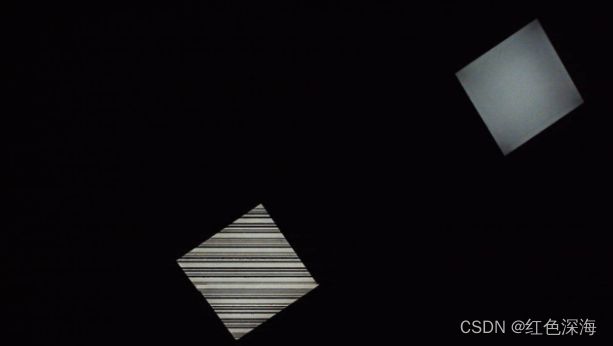

Figure 2. (a) Communication light source and imaging effect, (b) Analysis of CMOS rolling shutter imaging cycle
When imaging the light source, the CMOS is exposed line by line, and the signal of the light source on and off is recorded to form a light and dark fringe image as shown in Figure 3. In order to realize the imaging communication, the modulation frequency of VLC light source signal is required to adapt to the CMOS line exposure imaging time. Generally, the modulation time interval is required to be more than 2 times of CMOS line exposure time . At the same time, considering the requirements of indoor lighting, the bytecode should be converted into Manchester code, and the starting bit mark should be added before each bytecode to facilitate decoding. A bytecode can represent a hexadecimal number, and multiple bytecodes are concatenated to form the LED light source ID.

Figure 3. The modulation method of the LED light source ID
In visible light communication, the light and dark interval of the fringe signal (VLC_IFS) is related to the sending frequency of LED_ID signal’s modulation, and the frame rate and resolution of the imaging sensor. The clarity of fringe imaging is related to the camera's sensitivity value’s setting and the sensitivity of the sensor [ 11].
Taking the imaging of flat-panel light source as an example, the following four types of CMOS imaging sensors are used to image the same visible light communication light source, which are respectively the rear camera of the mobile phone used in Figure 4a, the front camera of the mobile phone used in Figure 4b, and the ordinary USB camera used in Figure 4c and the front camera of the laptop used in Figure 4d. As shown in Figure 4, the obtained fringe’s density and definition are different to some extent, the imaging in Figure 4a and Figure 4b is relatively clear, while the image’s gray scale distinction between light and dark stripes in Figure 4c and Figure 4d is not large. The fringe gray-scale fluctuation curves of the two imaging sensors respectively used in Figure 4b and Figure 4d are shown in Figure 5. The image of the sensor in Figure 4b is clear, the amplitude of the gray scale curve is large, which is easy to convert into high and low signals for decoding. While the image of the sensor in Figure 4d is blurred, and the amplitude of the gray scale curve is small, which is difficult to decode.
Meanwhile, due to the threshold delay effect of the CMOS sensor, VLC_IFS is constantly moving and changing on the image, so it is difficult to extract the LED_ID image signal in a standard period.
(a) (b) (c) (d)
Figure 4. The imaging effect of the same light source with different CMOS imaging sensors
Figure 5. Grayscale fluctuation curve of image stripes
2.2. Recognition Principle of Light Source Recognition
Visible light communication flat-panel light source cyclically broadcasts the ID information, which makes the light and dark stripe signals obtained by CMOS imaging form significant periodic characteristics. The period of VLC_IFS can be obtained by calculating the period of the autocorrelation sequence of the VLC_IFS (VLC_IFS_AS).
According to the correlation of the discrete time signals, the imaging fringe sequence signal is defined as ;
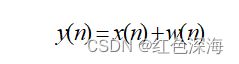 (1)
(1)
Where is the theoretical value of fringe gray value sequence of CMOS sensor imaging for communication light source, the period value is T unknown. represents the random noise of the fringe gray value sequence due to factors such as sensor sensitivity. Assuming that the observation sequence has M samples, M>>T. When or , If 0≤n≤M-1, the autocorrelation sequence of is as follows, where is the normalization factor.
(2)
(3)
Since is periodic, has the same period T as . When the value of is an integer multiple of the period T such as 0, T, 2T, the autocorrelation sequence curve will have a large peak value. In order to avoid the peak value decreasing in amplitude when approaching M, needs to be no greater than M/2。The peak value of the autocorrelation function of is at l=0. Due to its random characteristics, it will rapidly decay to zero. The signal is completely independent of random noise , and its cross-correlation and can be considered relatively small. Therefore, the number of cycles T can be determined by calculating the VLC_IFS_AS. As shown in Figure 6, the autocorrelation of fringe gray signals of the four CMOS imaging sensors used in Figure 4 is calculated. The results showed that the fringe signal period of the sensor used in Figure 4a was 179, the sensor used in Figure 4b was 119, the sensor used in Figure 4c was 76, and the sensor used in Figure 4d was 95, respectively. Different types of CMOS sensors image the same light source with different fringe signal periods.
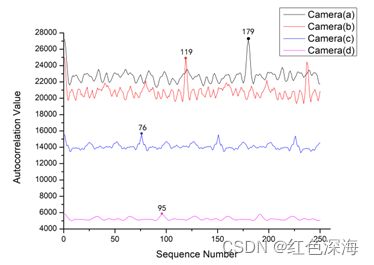
Figure 6. Autocorrelation sequence curves of the same light source with different CMOS sensors
Use the same model of CMOS sensor to analyze the autocorrelation sequence of the fringe signals imaged by four different communication light sources under the condition of image resolution of 1280×720, as shown in Figure 7, the autocorrelation period of the fringe signal of one light source is 76, and that of the rest three light sources is 90. The method of finding the period through autocorrelation can be used as a preliminary classification method to distinguish different light sources.
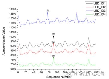
Figure 7. Autocorrelation sequence curves of different light sources with the same CMOS sensor

Figure 8. Light source matching process
A light source identification and matching method based on signal autocorrelation sequence is established according to the periodic characteristics of the VLC_IFS_AS. The process is shown in Figure 8. Firstly, the stripe image is averaged row by row to generate VLC_IFS, which is called . According to the sequence of light and dark fringes, the signal autocorrelation calculation is carried out to obtain the signal autocorrelation sequence and its period number, which can be respectively called , and T. The standardized sequence, which is called , , is obtained by extracting the sequence value in the first period of the signal autocorrelation sequence and performing normalization processing. The LED_ID matched-degree problem of two light sources is transformed into the matched-degree problem of the VLC_IFS_AS of two light sources. Define as the matched-degree sequence of two light sources, which can be defined as follows:
(4)
(5)
Where and are respectively represent the normalized signal autocorrelation sequences of two light sources in one cycle.
Use the SVM classification method, the standardized sequence of light source images can obviously be used as the classification elements of light sources with the same period but different LED_IDs, and the light source LED_ID identification can be converted into a classification problem. Similarly, the light source matching degree sequence can be used as the SVM classification element to convert the matching problem into a binary classification problem. Furthermore, the matching problem can be directly converted into a linear discriminant, and the definition of the matching degree K of two light sources is shown in Equation (6)
(6)
Where , , and are the coefficient, which are usually not less than 1. is the different value between the maximum and minimum values of the sequence , is the mean value of the sum of the absolute values of the sequence , is the standard deviation of the sequence , and is the average value of the sum of sequence values whose absolute value is greater than 0.15 in the sequence, the smaller the value, the higher the matching degree. If the matching degree of the images of the light source with the same LED_ID is made less than that of the images of the different light sources, the determination of the parameters can be converted into a linear programming problem to solve the quaternary first order inequality equations, and the value calculated between the matching light sources can be minimized through linear programming calculation to determine the parameter values. Obviously, the calculation elements of can also be converted into the calculation elements of SVM regression classification to carry out light source classification and recognition.
2.3. IMU-assisted Visual Positioning Method with Flat Panel Light Source
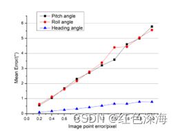
The corner points of the rectangular flat-panel light source are on an approximate plane. The visual imaging positioning using rectangular flat plate light source can be regarded as the PNP [21] pose calculation based on four points in the plane or the issue of single image space resection. The calculation can be divided into direct method and iterative method [24]. The direct method has high calculation efficiency, while the accuracy is poor compared with the iterative method. The calculation efficiency of the iterative method has a certain dependence on the initial value, a good initial value can reduce the number of iterations and improve the calculation efficiency. The combination of the two methods can improve the calculation accuracy and algorithm efficiency. The image point extraction error is the main source of the visual positioning error. According to the homography direct method [24], The Monte Carlo method is used for simulation, the focal length of the camera is set to 4.3mm, the imaging resolution is set to 1280×720, the camera is located in a 2m×2m plane, 3.5m directly below the light source, and the center of the VLC light source with a size of 60cm×60cm is imaged. Four theoretical image points of rectangular VLC light source are calculated, and then random errors are attached to the four image points for simulation. Place the camera in a 2m×2m plane, 3.5m directly below the light source, and image the center of the VLC light source with a size of 60cm×60cm. The simulation times are more than 1000 times, and the variation of the evaluation positioning error with the image point noise is shown in Figure 9a. with the increase of the image point error, the imaging positioning error increases linearly, and the plane error increases faster relative to the height error. The variation of the attitude angle error with the image point error is shown in Figure 9b. The growth rate of the tilt angle error is much faster than the heading angle, and the heading angle error does not exceed 1° at two pixels error levels.

| (a) |
(b) |
Figure 9. (a) The variation of imaging positioning error with the image point error (b) The variation of the imaging attitude error with the image point error
In Zhang’s calibration method [23], the homography matrix is , which can be expressed as follows: ,the R matrix of imaging attitude is obtained from , in the homography matrix , the translation relationship between the imaging measurement coordinate system and the world coordinate system is obtained from in the homography matrix , and the error of the imaging calculation attitude is transmitted to the camera position through the matrix. The common IMU attitude sensors can provide a tilt angle accuracy of 0.1°, which is far better than the tilt angle accuracy of the visual calculation, but the heading angle accuracy is usually greater than 2° and is susceptible to interference. Therefore, when the IMU is used to assist the imaging positioning, the heading angle calculated by the vision and the tilt attitude angle with higher accuracy provided by the IMU are used to correct the matrix, which can improve the imaging positioning accuracy [ 24].
Integrate the CMOS imaging sensor and IMU module into an imaging positioning module for imaging positioning simulation system with VLC flat-panel light source, as shown in Figure 10a, under the same imaging conditions, the simulation results after using a higher-precision tilt angle reorganization rotation matrix to participate in the positioning calculation are shown in Figure 10b, with the increase of the image point error, the plane accuracy of the imaging positioning is greatly improved. The error in the height direction is also reduced, indicating that the IMU-assisted imaging tilt attitude angle can improve the positioning accuracy. Similarly, in the calculation of the iterative method, the tilt angle can be fixed, and only the positioning value and heading angle can be iterated to further improve the positioning accuracy. Under the same conditions, the iterative method positioning simulation result is shown in Figure 10c. Under the condition of two pixels errors, the mean square error based on the IMU-assisted imaging positioning results in the three axis directions is less than 2 cm.

|
(a) |
(b) |
(c) |
Figure 10. (a) IMU-assisted visual positioning system based on VLC, (b) The variation of IMU-assisted positioning error with image point error, and (c) The variation of IMU-assisted iterative method positioning error with image point error
The digital image processing method is used to extract the boundary of the light source’s stripe region to obtain the contour points of the light source, and perform identification matching to obtain the four corner points’ coordinates of the rectangular flat light source corresponding to its ID information as shown in Figure 11.
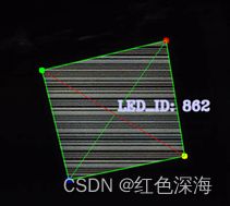
Figure 11. Visual recognition and extraction effect of rectangular communication light source
When determining the correspondence relation between the world coordinates of the corner points and the coordinates of the image points of the rectangular light source, firstly, a corresponding relation is assumed to calculate the imaging positioning and obtain the heading angle of the module at the same time. Then, the difference between the heading Angle and the geomagnetic deflection Angle of the IMU sensor is calculated. If the difference is less than a certain threshold, it is the correct relation; otherwise, the assumed calculation continues. The process is as follows:
step1.Input the world coordinates of the corner points of the light source in a counterclockwise sequence {p1,p2,p3,p4},and the light source corner point counterclockwise sequence image coordinates {c1,c2,c3,c4};
step2.Assume a correspondence between the world coordinate of the 4 corner points of the light source and the image coordinate sequence;
step3.Perform visual calculation according to the assumed relationship to obtain the heading angle H of the positioning module. At the same time obtain the geomagnetic azimuth angle M of the IMU sensor;
step4.Calculate the deviation angle C between the heading angle H and the geomagnetic azimuth angle M. Determine whether C is more than 45 degrees. if it is, return to the second step2, otherwise output the correspondence between the world coordinates of the light source corner points and the image coordinates; The deviation angle C is an empirical setting value. Usually, when the spatial coordinates of the reference point are consistent with the corresponding image point coordinates, the heading angle H calculated by the imaging positioning is not much different from the geomagnetic azimuth angle M provided by the IMU, generally not more than 10°, namely C=|H-M|<10. When the local magnetic azimuth is disturbed, the value of C may be larger. We assume that its threshold value is 45 degrees, mainly considering that in the positioning environment, the geomagnetic azimuth based on IMU sensor is prone to interference from magnetic field. When the threshold value exceeds 45 degrees, strong magnetic field interference will be received, resulting in inaccurate geomagnetic azimuth and errors in system judgment. Therefore, the threshold of the deviation angle C cannot exceed 45 degrees.
There are 4 kinds of sequence correspondences for the 4 corner points, so the corresponding relationship can be determined after four calculations at most. Finally, According to the correct correspondence, the IMU-assisted iterative method is used for imaging positioning calculation.
3. Experiment and Result
3.1. Introduction of Imaging Positioning Module
According to the visual method of IMU-assisted imaging measurement, a positioning module is made for algorithm verification. As shown in Figure 12, it has a binocular vision measurement function. The specific parameters are shown in Table 1. The module is used to achieve visual localization based on a single VLC circular light source [20]. In this experiment, one of the cameras is used for the monocular positioning test. The camera coordinate system and IMU coordinate system are calibrated before the test .
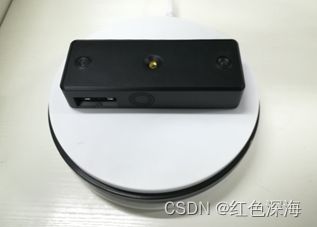
Figure 12. Visual imaging test positioning module
Table 1. Positioning module parameters
| Parameters |
Value |
| Camera focal length/mm |
4.3 |
| Maximum resolution |
1920×1080 |
| Binocular baseline/mm |
170 |
| IMU tilt angle accuracy/degree |
0.05-0.1 |
| IMU heading angle accuracy/degree |
1-4 |
| CPU |
ARM A53@ 1.4GHz 64 |
| Overall dimensions /mm |
210×72×38 |
3.2. Recognition Rate and Imaging Distance Relationship
The light source recognition rate of the light source visual matching method based on signal autocorrelation is related to many factors, such as the signal modulation period of the light source, the type of CMOS imaging sensor, the imaging distance, the angular resolution and so on. After determining the signal modulation frequency and the period of the light source, as well as the CMOS sensor’s type, the recognition rate of the light source based on signal autocorrelation is mainly related to the imaging resolution, the imaging distance, and the imaging angle and the image noise. A rectangular flat-panel LED lamp with a size of 548mm×548mm is used as the VLC light source, and the signal is modulated based on LED_ID technology. The modulation frequency is 16kHz, and Manchester code is used to form 3 hexadecimal numbers, with a total ID capacity of 4096. The positioning module adopts an imaging resolution of 1280×720. The recognition rate of the light source at different imaging distances is shown in Figure 13. When the imaging distance is less than 3.9m, the recognition rate is above 95%. When the imaging distance exceeds 4.2m, the recognition rate drops rapidly.
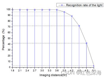
Figure 13. The relationship between the recognition rate of the light source and the imaging distance
When the parameters of the CMOS imaging sensor are fixed, the number of imaging fringes for the communication light source is mainly related to the distance between the imaging sensor and the light source and the imaging angle. The imaging distance affects the number of imaging fringes and the fringe gray levels’ degree of discrimination, but does not affect the calculation of the fringe signal’s period. When the imaging angle changes, the image of the light source is shaped like an affine quadrilateral, and the number of lines in the imaging area of the light source will also change accordingly, it’ll decrease or increase, which affects the recognition rate. When the number of image lines extracted from the light source area is less than the number of imaging cycles (T) of the light source signal, it cannot be recognized. Therefore, the use of a large-sized flat-panel light source can meet the requirements of longer-distance visible light communication imaging and positioning.
3.3. Multi-light Source Recognition and Positioning Test
The visual imaging positioning module is used to collect the imaging data of 5 rectangular flat LED light sources with the same communication frequency but different LED_IDs. The acquisition method is as follows: within the range of 3.5m from each light source, 14 images of light sources are collected at different imaging angles and distances, and a total of 70 samples are collected. After extracting the fringe grayscale sequence images of each sample image, noise expanded image samples are added randomly to the grayscale sequence image values, the number of samples is less than 10, and then 4610 training sets and 5160 test sets are generated according to the number of autocorrelation cycles of the fringe image sequences. Three schemes are used to perform SVM classification test by selecting the optimal parameters [25]. As shown in Table 2, Scheme 1 directly intercepts the light source fringe’s gray value sequence within one period as the classification element. Scheme 2 uses the autocorrelation sequence and the standardized sequence of the fringe image in one period as the classification elements. According to Equation (4), the sequence obtained by the difference between the autocorrelation sequences of two images in one period is used as the classification element, and the matching problem is transformed into a dichotomy problem.
Table 2. SVM classification accuracy rate of the three schemes under different conditions
| Scheme |
Autocorrelation |
Normalized |
Kernel |
Accuracy |
| 1 |
NO |
NO |
RBF |
20.16% |
| YES |
85.32% |
|||
| 2 |
YES |
NO |
LINEAR |
98.64% |
| YES |
100% |
|||
| 3 |
YES |
NO |
RBF |
88.26% |
| YES |
99.18% |
From the analysis of the SVM classification accuracy of the three schemes under different conditions in Table 2, extracting the autocorrelation sequence of the light source fringe image and normalizing it can ensure the accuracy of the classification. Scheme 1 directly uses the gray scale sequence of fringe image, which is not accurate. The SVM classification in scheme 2 uses a linear kernel function, and the accuracy after normalization reaches 100%, indicating that the light source image is linearly separable after signal autocorrelation. In scheme 3, the autocorrelation sequence of the image signals of two light sources is differentiated, and the multi-classification problem is transformed into a binary classification problem. The trained discriminant model can be extended to the matching discrimination of other light sources, and the accuracy is still above 98% in the discrimination of other light sources.
Further, according to the matching degree of the two light source images defined in Equation (6), the matching test is carried out. Ten images of each light source were selected from the collected image sets of the five light sources, and the standardized autocorrelation sequence Xi of each image was calculated respectively. Then, the average value sequence is taken as the matching template of the light source, and five matching template libraries are established. If the coefficients of equation (6) are all 1, the matching degree is calculated in the data set, and the values of each the component are shown in Figure 14. The first 50 data are the matching values between 10 images of each light source and its own template, while the last 200 data are the matching values between images of each light source and non-self template. As can be seen from the fluctuation of value, the maximum value of the first 50 data is 0.53, and the minimum value of the last 200 data is 0.59, indicating that value can be used as the threshold value of light source matching. The coefficient of the value’s calculation formula can be adjusted by linear programming method to improve the discrimination of matching threshold. Taking the minimum value as the matching basis, the recognition effect of multiple light sources within the imaging range is shown in Figure 15, which realizes the identification of multiple light source IDs and the extraction of rectangular contour points in the same image.
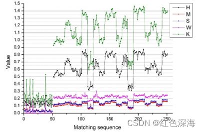
Figure 14. Matching degree and distribution of each component
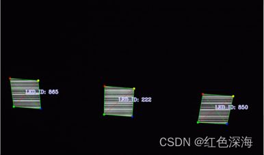
Figure 15. The recognition and matching effect of multiple light source
The positioning test is carried out in a laboratory environment of 11×8×3.5m. As shown in Figure 16, there are nine flat-panel LED light sources in total in the room, and 5 of them are modified as VLC positioning light sources by using visible light communication technology, and the spatial coordinates of each positioning light source’s four corner points is measured to establish a world coordinate system.
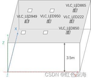
Figure 16. The layout of the communication light source in the test scenario
Use the IMU-assisted rectangular light source imaging positioning method mentioned in section 2.3 for positioning test which is divided into static test and mobile positioning test.When the imaging resolution of the imaging positioning module is set to 1280×720 and the vertical height from the light source is 3.4m, Static positioning was carried out at 21 positions in the area covered by the light source, and the positioning error of each point was shown in Figure 17. The plane positioning error of the module is less than 17 mm, and the height error is less than 30 mm.

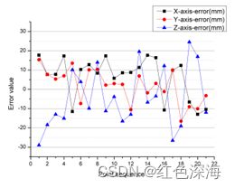
Figure 17. (a) Static positioning test’s points distribution, (b) Analysis of positioning accuracy of static positioning test’s points
Place the positioning module horizontally on the trolley and perform the IMU-assisted iterative mobile positioning test by controlling the trolley to move along the direction of the light source layout. When the height of the module is 3.12m from the light source and the imaging resolution is 1280×720, the plane positioning trajectory is shown in Figure 18, during the positioning process, the light source is identified accurately and the transition between different light sources is smooth.
. 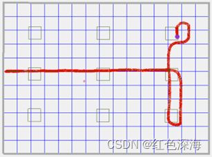
Figure 18. Moving and positioning plane trajectory among multiple light sources
Operate the car to make it move along the fixed rectangular line. The rectangular reference point and the positioning trajectory are shown in Figure 19a, and the lines of the trajectory and the reference point are basically coincident. Take the vertical distance between the plane positioning track point and the reference line as the plane positioning deviation, and take the difference between the positioning result along the Z-axis direction and the imaging distance as the height positioning deviation to analyze the mobile positioning accuracy. The result is shown in Figure 19b, the plane positioning deviation is less than 4.5cm, the height deviation is less than 6cm. As for the fluctuation of positioning error in the figure 19b, the initial analysis believes that it is caused by the larger mobile positioning error relative to the static positioning error, which may be caused by the fact that the corner extraction error of the light source in the moving state is relatively higher than that of the static positioning. When multiple light sources appear in the scene, the positioning accuracy is high, and the z-axis positioning error changes dramatically due to light source switching in the visual image. These details are worth further analysis.
|
|
|


Figure 19. (a) Rectangular mobile positioning test, (b) Analysis of IMU-assisted mobile positioning deviation
4 Discussions
The test results show that when the image resolution of 1280×720 and the distance of 3.5 m from the flat plate light source are adopted, the fast recognition and matching of multiple flat plate light sources with the size of 0.548 m×0.548 m can be realized simultaneously. With the assistance of the IMU attitude sensor, the planar mobile positioning accuracy is better than 4.5cm, and it can provide a directional reference of better than 1°, and the positioning frequency of the positioning module is greater than 10 Hz. With the upgrading of indoor lighting system, the method based on the fusion of visible light communication and visual imaging positioning provides a high-precision mobile positioning solution for indoor positioning, which can meet the application requirements of centimeter-level mobile positioning and navigation for indoor robot.
The positioning method proposed in this paper can only be effective in the area covered by VLC rectangular light source, and the reasonable layout of light source needs to be considered to achieve indoor continuous positioning. When there is not a complete light source image in the field of vision, positioning cannot be performed, which is a limiting factor for the promotion and application of all VLC imaging positioning. In order to overcome the influence of blind areas, the use of fisheye lens for imaging and positioning is one of the research directions to overcome this problem.
5. Conclusion.
A visual matching recognition and positioning method for visible light communication based on rectangular flat-panel LED light source is proposed. According to the CMOS shutter effect, the light and dark stripe images in the flat light source area are extracted by digital image processing method and the signal period was obtained by calculating the signal autocorrelation sequence of the stripe images. Then the normalized processing of the autocorrelation sequence signal in one period is carried out to transform the light source identification and matching problem into a SVM classification problem and establish the matching degree K’s calculation method of light source image, realizing the fast recognition and matching of light source ID information. Based on the realization of light source visual recognition, an IMU sensor-assisted imaging positioning method is proposed, and a positioning module is made for testing. The positioning test results show that the visible light communication visual positioning system based on the rectangular flat panel light source meets the need for centimeter-level positioning accuracy and provides a robust solution for indoor robot navigation.
References
- Li, Shaoxian, L. , Fan, W. , Chengrui, H. , & Yanzhao. (2020). Uwb positioning enhancement using markov chain in indoor nlos environment. The Journal of China Universities of Posts and Telecommunications.
- Huang Z., Zhou H., Li Y., Yang B., Xu Y., Zhou X., Bao H., Zhang G. , & Li H. .(2021)“VS-Net: Voting with Segmentation for Visual Localization”. IEEE Conference on Computer Vision and Pattern Recognition (CVPR), March.
- Shao, W. , Vijayarangan, S. , Cong, L. , & Kantor, G. . (2019). Stereo Visual Inertial LiDAR Simultaneous Localization and Mapping.
- Luo, J. , Fan, L. , & Li, H. . (2017). Indoor positioning systems based on visible light communication: state of the art. IEEE Communications Surveys & Tutorials, PP(4), 1-1.
- Yan, J. , Zhu, B. , Chen, L. , Wang, J. , & Liu, J. . (2019). Error analysis on indoor localization with visible light communication. Remote Sensing, 11(4).
- Amsters, R. , Demeester, E. , Stevens, N. , & Slaets, P. . (2021). Calibration of visible light positioning systems with a mobile robot. Sensors, 21(7).
- N Li, Qiao, Y. , Zhang, T. , & Lu, Y. . (2018). Dead-zone-free three-dimensional indoor positioning method based on visible light communication with dimensionality reduction algorithm. Optical Engineering, 57(3), 036114.1-036114.8.
- Ya, A. , Mi, A. , Ba, A. , Sr, B. , Sb, C. , & Wj, C. , et al. (2020). An experimental evaluation of a 3d visible light positioning system in an industrial environment with receiver tilt and multipath reflections. Optics Communications, 483.
- Zheng, Z. , Liu, L. , & Hu, W. . (2017). Accuracy of ranging based on dmt visible light communication for indoor positioning. IEEE Photonics Technology Letters, 29(8), 679-682.
- Xie, C. , Guan, W. , Wu, Y. , Fang, L. , & Cai, Y. . (2018). The led-id detection and recognition method based on visible light positioning using proximity method. IEEE Photonics Journal, 10(2), 1-16.
- Do, T. H. , & Yoo, M. . (2016). Performance analysis of visible light communication using cmos sensors. The Journal of Korean Institute of Communications and Information Sciences, 40(3), 309.
- Chen, C. W. , Chi-Wai, C. , Yang, L. , & Chien-Hung, Y. . (2017). Efficient demodulation scheme for rolling-shutter-patterning of cmos image sensor based visible light communications. Optics Express, 25(20), 24362.
- Ma, Y. W. , Chen, J. L. , & Chen, Z. Z. . (2019). A high accuracy and efficiency indoor positioning system with visible light communication. Transactions on Emerging Telecommunications Technologies, e3452.
- Guan, W. , Wu, Y. , Xie, C. , Fang, L. , Liu, X. , & Chen, Y. . (2018). Performance analysis and enhancement for visible light communication using cmos sensors. Optics Communications, 410, 531-545.
- Guan, W. , Wen, S. , Liu, L. , & Zhang, H. . (2019). High-precision indoor positioning algorithm based on visible light communication using complementary metal–oxide–semiconductor image sensor. Optical Engineering, 58(2), 1.
- Zhang, H. , Li, Y. , Guan, W. , Li, J. , Zheng, J. H. , & X Zhang. (2019). The optical fringe code modulation and recognition algorithm based on visible light communication using convolutional neural network. Signal Processing Image Communication, 75, 128-140.
- Wu, Y. , Guan, W. , Zhang, X. , Huang, M. , & Cao, J. . (2019). Visible light positioning system based on cmos image sensor using particle filter tracking and detecting algorithm. Optics Communications, 444, 9-20.
- Ji, Y. Q. , Xiao, C. X. , Gao, J. , Ni, J. M. , Cheng, H. , & Zhang, P. C. , et al. (2019). A single led lamp positioning system based on cmos camera and visible light communication. Optics Communications.
- Kim, J. Y. , Yang, S. H. , Son, Y. H. , & Han, S. K. . (2016). High-resolution indoor positioning using light emitting diode visible light and camera image sensor. Iet Optoelectronics, 10(5), 184-192.
- SUN S Z, LI G Y,FENG Q Q,WANG LI,(2020). Indoor positioning based on visible light communication and binocular vision. Opt.Precision Eng,28(04),834-843.
- Lepetit, V. , Moreno-Noguer, F. , & Fua, P. . (2009). Epnp: an accurate o(n) solution to the pnp problem. International Journal of Computer Vision, 81(2), p.155-166.
- Gong, H. , Jiang, T. , Jiang, G. , & Chen, M. . (2011). A globally convergent algorithm of space resection based on quaternion. Acta Geodaetica et Cartographica Sinica, 40(5), 639-645.
- Zhang, Z. . (1999). Flexible camera calibration by viewing a plane from unknown orientations. Seventh IEEE International Conference on Computer Vision. IEEE.
- SUN S Z, LI G Y, WANG L, & FENG Q. . (2021). High-precision visual indoor positioning method with the rectangular light source based on visible light communication. Journal of Geomatics Science and Technology, 38(3), 8.
- Wu, K. P. , & Wang, S. D. . (2009). Choosing the kernel parameters for support vector machines by the inter-cluster distance in the feature space. Pattern Recognition, 42(5), 710-717.