YUVToRGB(CUDA Conversion)库的学习
目录
-
- 前言
- 1. YUVToRGB
-
- 1.1 Supported Feature
- 1.2 Performance
-
- 1.2.1 Performance Table
- 1.2.2 How to Benchmark
- 1.2.3 How to Verify the Accuracy
- 1.3 User Integration
- 1.4 Summary
- 2. YUVToRGB案例
-
- 2.1 环境配置
- 2.2 run案例
- 3. YUVToRGB浅析
- 4. 补充知识
-
- 4.1 YUV不同格式区别
- 4.2 Luma 和 Chroma
- 4.3 stride
- 4.4 YUVToRGB的Python实现
- 总结
- 参考
前言
学习 Lidar_AI_Solution 项目中的 YUVToRGB(CUDA Conversion)
本文主要对 YUV2RGB 库进行简单分析并使用,博主为初学者,欢迎交流讨论,若有问题欢迎各位看官批评指正!!!
1. YUVToRGB
Copy自:https://github.com/NVIDIA-AI-IOT/Lidar_AI_Solution/blob/master/libraries/YUVToRGB/README.md
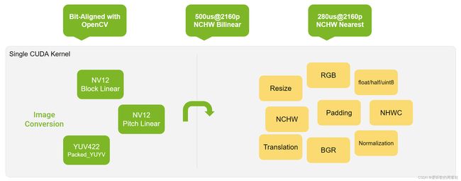
YUV 图像到 RGB 图像的转换,将 Resize/Padding/Conversion/Normalization 合并为一个核函数
-
大部分时候可以与 OpenCV 进行字节对齐
- 当缩放因子 scale 为有理数时,可以给出精确的结果
- 当步长 stride 可以被 4 整除时,通常可以获得更好的性能
-
支持的输入格式:
- NV12BlockLinear
- NV12PitchLinear
- YUV422Packed_YUYV
-
支持的插值方法:
- Nearest
- Bilinear
-
支持的输出数据类型:
- Uint8
- Float32
- Float16
-
支持的输出布局:
- CHW_RGB/BGR
- HWC_RGB/BGR
- CHW16/32/4/RGB/BGR for DLA input
-
支持的功能:
- Resize
- Padding
- Conversion
- Normalization
该库使用单个 CUDA 核即可实现 YUV → \rightarrow → RGB 的批量转换
1.1 Supported Feature
- 输入格式可以是 YUV_NV12 Block Linear 或者 YUV_NV12 Pitch Linear 或者 YUV_YUYV Packed
- GPU 的输出可以是 RGB/BGR NCHW 或者 RGB/BGR NHWC,DLA 的输出可以是 RGB/BGR NCHW16
- 转换公式 R/G/B_output = (R/G/B - offset_R/G/B) * scale_R/G/B
- 支持最近邻插值和双线性插值两种插值方式
- 经过验证,输出结果与 OpenCV 完全相同
- 在特定 CUDA stream 上运行的异步 API
- 命令行:
$ ./yuvtorgb --help
Usage: ./yuvtorgb --input=3840x2160x1/BL --output=1280x720/uint8/NCHW_RGB --interp=nearest --save=tensor.binary --perf

parameters:
    --input:  Set input size and format, Syntax format is: [width]x[height]x[batch]/[format]
              format can be 'BL' or 'PL' or 'YUYV'
    --output: Set output size and layout, Syntax format is: [width]x[height]/[dtype]/[layout]
              dtype can be 'uint8', 'float16' or 'float32'
              layout can be one of the following: NCHW_RGB NCHW_BGR NHWC_RGB NHWC_BGR for GPU, NCHW16_RGB NCHW16_BGR for DLA
    --interp: Set rescale mode. Here the choice 'nearest' or 'bilinear', default is nearest
    --save:   Set the path of the output. default does not save the output
    --perf:   Launch performance test with 1000x warmup and 1000x iteration
1.2 Performance
1.2.1 Performance Table
| Input | Block Linear YUV | |||||
|---|---|---|---|---|---|---|
| Foumal | R/G/B_Output = (R/G/B - offset_R/G/B) * scale_R/G/B | |||||
| Environment | Orin-DOS6.0.3.0(30270381) / CUDA11.4.15 / BATCH=1 / CPU@2010MHz / GPU@1275MHz / EMC@3199MHz | |||||
| Output(RGB) | NHWC (us) | NCHW (us) | NCHW16 (us) | |||
| Input-Output | 3840x2160-1920x1080 | 1920x1080-1080x720 | 3840x2160-1920x1080 | 1920x1080-1080x720 | 3840x2160-1920x1080 | 1920x1080-1080x720 |
| FP32/Nearest | 314.69 | 124.63 | 247.62 | 89.54 | 1221.38 | 437.55 |
| FP16/Nearest | 287.11 | 112.19 | 168.13 | 64.26 | 1037.24 | 353.84 |
| UINT8/Nearest | 272.24 | 105.85 | 136.06 | 54.21 | 632.93 | 202.67 |
| FP32/Bilinear | 549.77 | 202.69 | 472.32 | 183.85 | 1449.23 | 508.97 |
| FP16/Bilinear | 518.23 | 194.04 | 371.32 | 145.82 | 1145.20 | 386.06 |
| UINT8/Bilinear | 503.39 | 189.02 | 435.90 | 169.14 | 756.36 | 264.71 |
1.2.2 How to Benchmark
- 步骤1:
make yuvtorgb生成可执行程序 - 步骤2:
./yuvtorgb --input=3840x2160x1/BL --output=1280x720/uint8/NCHW_RGB --interp=nearest --perf- 特定配置下的简单性能测试
$./yuvtorgb --input=3840x2160x1/BL --output=1280x720/uint8/NCHW_RGB --interp=nearest --perf
[Nearest] 3840x2160x1/NV12BlockLinear to 1280x720/Uint8/NCHW_RGB performance: 30.32 us
1.2.3 How to Verify the Accuracy
- 检查:生成二进制文件并调用 Python 脚本来做错误检查
- 验证以下 2 个方面:
- 色彩空间转换
- 使用相同的公式,因此得到的结果应该完全相同
- 插值方式
- 最近邻:在多个分辨率下进行验证,得到完全相同的结果
- 双线性:当使用的缩放因子为有理数时,可获取完全相同的结果。否则,偏差不超过 1 个像素
- 色彩空间转换
$ pip install numpy opencv-python
$ make compare
Compile depends CUDA src/yuv_to_rgb_kernel.cu
Compile depends C++ src/main.cpp
Compile depends C++ src/yuv_to_rgb.cpp
Compile CXX src/yuv_to_rgb.cpp
Compile CXX src/main.cpp
Compile CUDA src/yuv_to_rgb_kernel.cu
Link yuvtorgb
rm -rf workspace/*.bin workspace/*.png
python ./compare-with-opencv.py
nearest: 3840x2160x1/BL to 1920x1280/uint8/NCHW16_BGR, diff sum = 0, avg = 0.0, max = 0, std = 0.0
nearest: 3840x2160x1/BL to 1920x1280/uint8/NCHW16_RGB, diff sum = 0, avg = 0.0, max = 0, std = 0.0
nearest: 3840x2160x1/BL to 1920x1280/uint8/NCHW_BGR, diff sum = 0, avg = 0.0, max = 0, std = 0.0
1.3 User Integration
- 只需要包含 yuvtorgb_library/yuv_to_rgb_kernel.cu 和 yuvtorgb_library/yuv_to_rgb_kernel.hpp 即可集成
- 提供纯 C 风格的接口
- 生成动态库:
nvcc -Xcompiler "-fPIC" -shared -O3 yuvtorgb_library/yuv_to_rgb_kernel.cu -o libyuvtorgb_kernel.so -lcudart
1.4 Summary
针对 BL8800 (视频编码器默认值)
- UVplane 在使用 cudaMallocArray 时使用的是 cudaCreateChannelDesc(8, 8, 0, 0)
- 此时每个像素占用 2 个字节
- 当使用 cudaMallocArray,UVplane 的大小为:image_width / 2,image_height / 2。因为每个像素占用 2 个字节
- cudaMemcpy2DToArrayAsync,当用户数据复制到 cudaArray 时,width = image_width,height = image_height / 2。复制时,宽度为字节单位
- 对于 cuda 核函数,读取时使用
uv = tex2D(chroma, x/2, y/2)
针对 BL8000
- UVplane 在使用 cudaMallocArray 时使用的是 cudaCreateChannelDesc(8, 0, 0, 0)
- 此时每个像素占用 1 个字节
- 当使用 cudaMallocArray,UVplane 的大小为:image_width,image_height / 2。因为每个像素占用 1 个字节
- cudaMemcpy2DToArrayAsync,当用户数据复制到 cudaArray 时,width = image_width,height = image_height / 2。复制时,宽度为字节单位
- 对于 cuda 核函数,读取时使用
u = tex2D(chroma, int(x/2)*2+0, y/2); v = tex2D (chroma, int(x/2)*2+1, y/2)
2. YUVToRGB案例
2.1 环境配置
由于 YUVToRGB 仅依赖于 CUDA,因此如果在系统环境变量中已经添加 CUDA 路径,则可以直接 make run 运行看效果,如果没有把 CUDA 添加到系统环境变量中,则手动指定下即可,如下所示:
# Makefile 第 28 行
cuda_home := /usr/local/cuda-11.6
指定好之后,二话不说直接执行 make run 看下能否成功执行,如下图所示:
OK!成功运行了,起码整个代码没有问题,我们可以执行 ./yuvtorgb --help 看看参数说明,如下图所示:
2.2 run案例
run 函数的主要功能是从指定文件中读取一个 YUV 图像数据,将其复制到 GPU,然后在 GPU 上将该 YUV 图像转换为 RGB 格式,并将转换后的 RGB 图像保存到文件中。
指令如下:
./yuvtorgb --input=3840x2160x1/YUYV --output=1280x720/uint8/NCHW_RGB --interp=nearest --save=workspace/demo.binary --perf
运行效果如下:
转换的 RGB 图像如下图所示:
3. YUVToRGB浅析
主要对 main.cpp 中的 run 函数进行分析
run 函数参数如下:
- perf:true,性能测试
- save:RGB 图像二进制文件保存路径
- input_width:3840,YUV 输入图像宽度
- input_height:2160,YUV 输入图像高度
- input_batch:1,YUV 图像输入批次
- input_format:YUVFormat::NV12BlockLinear,YUV 图像格式(UV分量交叉存储)
- output_width:1280,RGB 输出图像宽度
- output_height:720,RGB 输出图像高度
- output_layout:PixelLayout::NCHW_RGB,输出图像数据的排列方式
- output_dtype:DataType::Uint8,输出图像的数据类型
- interp:Interpolation::Nearest,插值方式
首先 run 函数一进来就通过 load_yuv 函数从指定路径加载了 YUV 格式的图像数据,其主要是通过 read_yuv 来读取指定路径和格式的 YUV 图像,read_yuv 函数的实现如下:
YUVHostImage* read_yuv(const string& file, int width, int height, YUVFormat format){

    if((width % 2 != 0) || (height % 2 != 0)){
        std::fprintf(stderr, "Unsupport resolution. %d x %d\n", width, height);
        return nullptr;
    }

    fstream infile(file, ios::binary | ios::in);
    if(!infile){
        std::fprintf(stderr, "Failed to open: %s\n", file.c_str());
        return nullptr;
    }

    infile.seekg(0, ios::end);

    // check yuv size
    size_t file_size   = infile.tellg();
    size_t y_area      = width * height;
    size_t except_size = y_area * 3 / 2;
    size_t stride      = width;
    if(format == YUVFormat::YUV422Packed_YUYV){
        except_size = y_area * 2;
        stride      = width * 2;
    }

    if(file_size != except_size){
        std::fprintf(stderr, "Wrong size of yuv image : %lld bytes, expected %lld bytes\n", file_size, except_size);
        return nullptr;
    }

    YUVHostImage* output = new YUVHostImage();
    output->width  = width;
    output->height = height;
    output->stride = stride;
    output->y_area = y_area;
    output->data   = new uint8_t[except_size];
    output->format = format;

    infile.seekg(0, ios::beg);
    if(!infile.read((char*)output->data, except_size).good()){
        free_yuv_host_image(output);
        std::fprintf(stderr, "Failed to read %lld byte data\n", y_area);
        return nullptr;
    }
    return output;
}
该函数的目的是从给定的文件路径读取 YUV 图像,并返回一个 YUVHostImage 结构体的指针,该结构体包含读取到的图像数据及其相关属性。
YUVHostImage 结构体的定义如下:
struct YUVHostImage{
    uint8_t* data = nullptr;
    unsigned int width  = 0, height = 0;
    unsigned int y_area = 0;
    unsigned int stride = 0;
    YUVFormat format = YUVFormat::NoneEnum;
};
在 read_yuv 函数中,我们先会去检查 YUV 图像的宽度和高度,如果不是偶数则返回,然后我们会以二进制模式打开文件,如果打开失败则直接返回。接着我们会对 YUV 图像文件的大小做一个检查,具体代码如下:
// check yuv size
size_t file_size   = infile.tellg();
size_t y_area      = width * height;
size_t except_size = y_area * 3 / 2;
size_t stride      = width;
if(format == YUVFormat::YUV422Packed_YUYV){
    except_size = y_area * 2;
    stride      = width * 2;
}

if(file_size != except_size){
    std::fprintf(stderr, "Wrong size of yuv image : %lld bytes, expected %lld bytes\n", file_size, except_size);
    return nullptr;
}
可以看到在 size 检查中针对于 NV12BlockLinear 和 NV12PitchLinear 格式的 YUV 图像,我们期望的 size = width x height x 3 / 2,而针对于 YUV422Packed_YUYV 格式的 YUV 图像,我们期望的 size = width x height x 2
那你可能会问,为什么我们期望的 size 不是直接等于 width x height 呢?
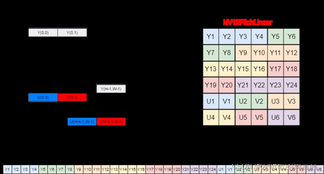
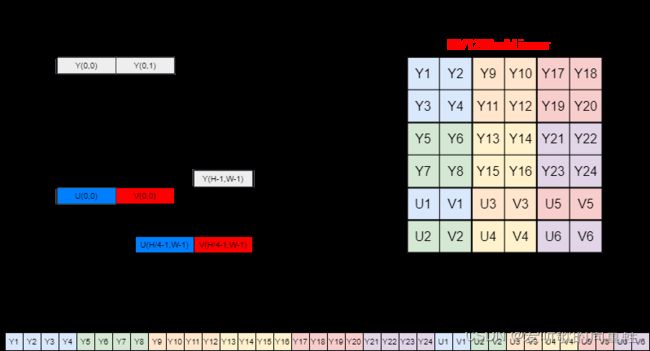
这其实是和 YUV 的存储方式相关的,YUV 存储格式 有多种,这里的 YUV 采用的是 NV12PitchLinear 格式,其存储结构和数据排列如下图所示:
NV12 格式的特点是它的 Y 通道和 UV 通道是分开的,我们会先连续存储所有像素点的 Y,紧接着 UV 交错存储。而 YUV 的 采样格式 也存在多种,一般最常见的就是 4:2:0,即每四个 Y 分量共用一组 UV 分量,如上图所示。对于一个 nv12_3840x2160 的 YUV 的图像我们所说的宽高 3840x2160 其实指的是 Y 分量的大小,而四个 Y 分量共用一组 UV 分量,因此 UV 分量的高度只有 Y 分量高度的一半,所以 NV12PitchLinear 格式的 YUV 图像总的数据量为 width x height + width x height / 2 = width x height x 3 / 2,其中第一部分是 Y 分量的大小,第二部分是 UV 分量的大小,因此我们在 read_yuv 函数中看到了如上的 size 检查代码。
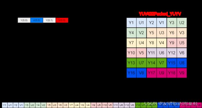
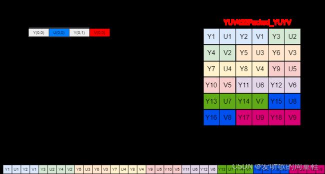
而对于 YUV422Packed_YUYV 格式的 YUV 图像,其存储结构和数据排列如下图所示:
在 YUV422Packed_YUYV 格式中,每两个 Y 分量共用一组 UV 分量,即每两个像素使用四个字节(Y0,U,Y1,V)表示,所以对于一个给定的图像,总的数据量是 width * height * 2
在对 size 进行检查后我们会创建一个新的 YUVHostImage 结构体实例指针 output,并设置它的属性如宽度、高度、步长、格式等,然后我们会将加载的 YUV 图像文件中的数据读取到 output → \rightarrow →data 中,读取成功后会返回指向 YUVHostImage 结构体的指针,该结构体包含读取到的 YUV 图像数据及其相关属性。
在加载完 YUV 图像后,我们定义了一个 FillColor 结构体实例 color,并将其三个颜色通道分别设置为了 0、255 和 128,然后我们创建了一个非阻塞的 CUDA 流,用于后续 GPU 上的异步操作。接着我们通过 create_yuv_gpu_image 函数在 GPU 上创建了一个空的 YUV 图像数据,其实现如下:
YUVGPUImage* create_yuv_gpu_image(int width, int height, int batch_size, YUVFormat format){

    YUVGPUImage* output = new YUVGPUImage();
    output->width  = width;
    output->height = height;
    output->batch  = batch_size;
    output->format = format;
    output->stride = width;

    if(format == YUVFormat::NV12PitchLinear){
        checkRuntime(cudaMalloc(&output->luma,   width * height * batch_size));
        checkRuntime(cudaMalloc(&output->chroma, width * height / 2 * batch_size));
    }else if(format == YUVFormat::NV12BlockLinear){
        cudaChannelFormatDesc YplaneDesc = cudaCreateChannelDesc(8, 0, 0, 0, cudaChannelFormatKindUnsigned);
        checkRuntime(cudaMallocArray((cudaArray_t*)&output->luma_array,   &YplaneDesc, width, height * batch_size, 0));

        // One pixel of the uv channel contains 2 bytes
        cudaChannelFormatDesc UVplaneDesc = cudaCreateChannelDesc(8, 8, 0, 0, cudaChannelFormatKindUnsigned);
        checkRuntime(cudaMallocArray((cudaArray_t*)&output->chroma_array, &UVplaneDesc, width / 2, height / 2 * batch_size, 0));

        cudaResourceDesc luma_desc = {};
        luma_desc.resType         = cudaResourceTypeArray;
        luma_desc.res.array.array = (cudaArray_t)output->luma_array;

        cudaTextureDesc texture_desc = {};
        texture_desc.filterMode = cudaFilterModePoint;
        texture_desc.readMode   = cudaReadModeElementType;
        checkRuntime(cudaCreateTextureObject((cudaTextureObject_t*)&output->luma, &luma_desc, &texture_desc, NULL));

        cudaResourceDesc chroma_desc = {};
        chroma_desc.resType         = cudaResourceTypeArray;
        chroma_desc.res.array.array = (cudaArray_t)output->chroma_array;
        checkRuntime(cudaCreateTextureObject((cudaTextureObject_t*)&output->chroma, &chroma_desc, &texture_desc, NULL));
    }else if(format == YUVFormat::YUV422Packed_YUYV){
        output->stride = width * 2;
        checkRuntime(cudaMalloc(&output->luma, output->stride * height * batch_size));
    }
    return output;
}
该函数的目的是在 GPU 上为给定的 YUV 图像分配一块内存,并返回一个 YUVGPUImage 结构体的指针,该结构体包含了分配的 YUV 图像的内存和其他相关信息,其结构体的定义如下:
struct YUVGPUImage{
    void* luma   = 0;     // y
    void* chroma = 0;     // uv
    void* luma_array   = nullptr;        //  nullptr if format == PL
    void* chroma_array = nullptr;        //  nullptr if format == PL
    unsigned int width = 0, height = 0;
    unsigned int stride = 0;
    unsigned int batch = 0;
    YUVFormat format  = YUVFormat::NoneEnum;
};
在 create_yuv_gpu_image 函数中,我们先创建了一个新的 YUVGPUImgae 结构体实例指针 output,并设置它的属性如宽度、高度、步长、格式等,然后我们会根据 YUV 的格式分配 GPU 内存:
NV12PitchLinear格式:
- 直接使用 cudaMalloc 分配 GPU 内存,Y 通道(luma)分配的大小是 width x height,UV 通道(chroma)分配的大小是 width x height / 2
NV12BlockLinear格式:
-
当格式为 NV12BlockLinear 时,处理的方式与传统的 NV12PitchLinear 格式不同,对于 Y 通道(luma)和 UV 通道(chroma),都使用的是 CUDA 的数组结构即 cudaMallocArray 进行内存分配
-
我们先使用了 cudaCreateChannelDesc 定义了 Y 通道和 UV 通道格式描述符,值得注意的是在这里 UVPlane 使用的是 BL8800 其大小为 width / 2,height / 2。这是因为每个像素的 UV 通道包含 2 个字节,所以宽度减半
-
然后使用 cudaCreateTextureObject 函数为 Y 和 UV 通道创建了纹理对象,这使得在 GPU 上处理图像时可以直接从纹理内存中获取像素值,从而提高性能(CUDA 内存模型)
YUV422Packed_YUYV格式:
- 同样直接使用 cudaMalloc 分配 GPU 内存,但步长 stride 被设置为 width x 2,因为每两个像素使用四个字节(Y0,U,Y1,V)表示
- 仅为 Y 通道(luma)分配了 GPU 内存,实际上是包括了 YUYV 值,因为分配的大小为 stride x height = width x height x 2
在分配完内存后将 YUVGPUImage 指针返回,其中包含了为 YUV 图像分配的内存和图像的属性。
在创建 NV12BlockLinear 格式的 YUV 图像时,对 UV 通道描述符使用的是 BL8800,那在之前还提到过 BL8000,二者有什么区别呢?
其实在 README 中已经详细描述了二者的不同,这边再简单分析下
BL8800:
- UVplane 描述符:使用 cudaCreateChannelDesc(8, 8, 0, 0)。这意味着每个 UV 像素包含两个 8 位值(一个 U 和一个 V),总共占用 2 个字节
- cudaMallocArray 大小:UV 平面的大小是 image_width / 2 和 image_height / 2。这是因为每个 UV 对占用 2 个字节,所以宽度减半。
- cudaMemcpy2DToArrayAsync:当将用户数据复制到 cudaArray 时,宽度 = image_width,高度 = image_height / 2。值得注意的是,复制时的宽度是以字节为单位的,所以虽然 UV 平面的实际宽度是原始图像宽度的一半,但复制时的宽度是完整的图像宽度。
- CUDA 核函数读取:使用 uv = tex2D
(chroma, x/2, y/2) 从 UV 平面中读取数据。这是因为 UV 值是交错存储的,所以需要使用 uchar2 类型。
BL8000:
- UVplane 描述符:使用 cudaCreateChannelDesc(8, 0, 0, 0)。这意味着每个 UV 像素只包含一个 8 位值,总共占用 1 个字节
- cudaMallocArray 大小:UV 平面的大小是 image_width 和 image_height / 2。虽然每个像素只占用 1 字节,但由于 U 和 V 值是分开的(不是交错的),所以宽度保持不变。
- cudaMemcpy2DToArrayAsync:与 BL8800 相同,当将用户数据复制到 cudaArray 时,宽度 = image_width,高度 = image_height / 2。
- CUDA 核函数读取:使用两次读取来分别获取 U 和 V 值:*u = tex2D
(chroma, int(x/2)2+0, y/2) 和 v = tex2D(chroma, int(x/2)*2+1, y/2) 。这是因为 U 和 V 值是分开存储的,而不是交错的。
OK!通过 create_yuv_gpu_image 函数我们在 GPU 上创建了一个空的 YUV 图像,接着我们通过 create_rgb_gpu_image 函数在 GPU 上创建了一个空的 RGB 图像,其实现如下:
RGBGPUImage* create_rgb_gpu_image(int width, int height, int batch, PixelLayout layout, DataType dtype){

    RGBGPUImage* output = new RGBGPUImage();
    int channel = 0;
    int stride  = 0;

    switch(layout){
    case PixelLayout::NHWC_RGB:
    case PixelLayout::NHWC_BGR:
        channel = 3; stride = width * channel;
        break;
    case PixelLayout::NCHW_RGB:
    case PixelLayout::NCHW_BGR:
        channel = 3; stride = width;
        break;
    case PixelLayout::NCHW4_RGB:
    case PixelLayout::NCHW4_BGR:
        channel = 4; stride = width * channel;
        break;
    case PixelLayout::NCHW16_RGB:
    case PixelLayout::NCHW16_BGR:
        channel = 16; stride = width * channel;
        break;
    case PixelLayout::NCHW32_RGB:
    case PixelLayout::NCHW32_BGR:
        channel = 32; stride = width * channel;
        break;
    }

    auto bytes = width * height * channel * batch * dtype_sizeof(dtype);
    checkRuntime(cudaMalloc(&output->data, bytes));
    output->width   = width;
    output->height  = height;
    output->batch   = batch;
    output->channel = channel;
    output->stride  = stride;
    output->layout  = layout;
    output->dtype   = dtype;
    return output;
}
该函数的目的是在 GPU 上为给定的像素布局和数据类型来创建一个 RGB 图像。函数返回一个 RGBGPUImage 结构体的指针,该结构体包含 GPU 上的图像数据和相关属性,定义如下:
struct RGBGPUImage{
    void* data  = nullptr;
    int width   = 0, height = 0;
    int batch   = 0;
    int channel = 0;
    int stride  = 0;
    PixelLayout layout = PixelLayout::NoneEnum;
    DataType dtype     = DataType::NoneEnum;
};
在 create_rgb_gpu_image 函数中,我们先创建了一个新的 RGBGPUImage 结构体实例指针 output,然后根据像素布局来设置通道数 channel 和步长 stride,接着计算了图像所需的总字节数并使用 cudaMalloc 为图像数据分配 GPU 内存。最后设置了输出图像的属性,包括宽度、高度、步长等,并返回一个指向新创建的图像的 RGBGPUImage 指针。
为什么在 NHWC_RGB 布局中的 stride = width * channel,而 NCHW_RGB 布局中的 stride = width 呢?
NHWC:(from chatGPT)
- 在这种布局中,通道是最内层的维度。这意味着,对于一个给定的像素,其 R、G 和 B 通道值是连续存储的
- 例如,对于一个 3x3 的 RGB 图像,其内存布局可能是这样的(简化表示):R1G1B1 R2G2B2 R3G3B3 …
- 因此,一行中的步长 stride 是其宽度乘以通道数。这是因为,为了从这一行的开始到下一行的开始,需要跳过当前行中所有像素的所有通道。所以对于 NHWC_RGB 而言其 stride = width * channel
NCHW:
- 在这种布局中,通道是第二个维度。这意味着,对于一个给定的像素,其 R、G 和 B 通道值是分开存储的
- 例如,对于一个 3x3 的 RGB 图像,其内存布局可能是这样的(简化表示):所有 R 值,然后是所有 G 值,接着是所有 B 值。像这样:R1 R2 R3 … G1 G2 G3 … B1 B2 B3
- 因此,一行中的步长 stride 只是其宽度,因为每个像素只有一个通道值。其他通道的值在其他部分的内存中。所以,对于 NCHW_RGB 而言其 stride = width
在创建完 RGB 输出图像后,我们会利用 copy_yuv_to_gpu 函数将 YUV 格式的图像数据从主机(CPU)复制到设备(GPU)中,其实现如下:
void copy_yuv_host_to_gpu(const YUVHostImage* host, YUVGPUImage* gpu, unsigned int ibatch, unsigned int crop_width, unsigned int crop_height, cudaStream_t stream){

    if(crop_width > host->width || crop_height > host->height){
        std::fprintf(stderr, "Failed to copy, invalid crop size %d x %d is larger than %d x %d\n", crop_width, crop_height, host->width, host->height);
        return;
    }

    if(crop_width > gpu->width || crop_height > gpu->height){
        std::fprintf(stderr, "Failed to copy, invalid crop size %d x %d is larger than %d x %d\n", crop_width, crop_height, gpu->width, gpu->height);
        return;
    }

    if(ibatch >= gpu->batch){
        std::fprintf(stderr, "Invalid ibatch %d is larger than %d, index out of range.\n", ibatch, gpu->batch);
        return;
    }

    if(host->format == YUVFormat::YUV422Packed_YUYV){
        if(gpu->format != YUVFormat::YUV422Packed_YUYV){
            std::fprintf(stderr, "Copied images should have the same format. host is %s, gpu is %s\n", yuvformat_name(host->format), yuvformat_name(gpu->format));
            return;
        }
    }

    if(gpu->format == YUVFormat::NV12PitchLinear){
        checkRuntime(cudaMemcpy2DAsync(gpu->luma + ibatch * gpu->stride * gpu->height,   gpu->stride, host->data,              host->stride,
            crop_width, crop_height,     cudaMemcpyHostToDevice, stream));
        checkRuntime(cudaMemcpy2DAsync(gpu->chroma + ibatch * gpu->stride * gpu->height / 2, gpu->stride, host->data + host->y_area, host->stride,
            crop_width, crop_height / 2, cudaMemcpyHostToDevice, stream));
    }else if(gpu->format == YUVFormat::NV12BlockLinear){
        checkRuntime(cudaMemcpy2DToArrayAsync((cudaArray_t)gpu->luma_array,   0, ibatch * gpu->height,     host->data,              host->stride,
            crop_width, crop_height,     cudaMemcpyHostToDevice, stream));
        checkRuntime(cudaMemcpy2DToArrayAsync((cudaArray_t)gpu->chroma_array, 0, ibatch * gpu->height / 2, host->data + host->y_area, host->stride,
            crop_width, crop_height / 2, cudaMemcpyHostToDevice, stream));
    }else if(gpu->format == YUVFormat::YUV422Packed_YUYV){
        checkRuntime(cudaMemcpy2DAsync(gpu->luma + ibatch * gpu->stride * gpu->height,   gpu->stride, host->data,              host->stride,
            crop_width * 2, crop_height,     cudaMemcpyHostToDevice, stream));
    }
}
该函数的主要目的是将 YUV 图像数据从 CPU 拷贝到 GPU 上。为此,它考虑了不同的 YUV 格式,并为每种格式执行适当的拷贝操作。
首先我们会检查拷贝的有效性,检查所提供的裁剪宽度和高度是否合适,确保裁剪尺寸不超过主机图像或 GPU 图像的尺寸,它还确保提供的批处理索引 ibatch 不超过 GPU 图像的批处理大小
然后我们会检查 YUV 格式的兼容性,如果主机图像是 YUV422Packed_YUYV 格式,需要确保 GPU 图像也是同样的格式。
接下来我们会考虑三种不同的格式,并为每种格式执行适当的拷贝操作
NV12PitchLinear:
- 这种格式的 Y 和 UV 数据是分开的。Y 数据在前,UV 数据在后
- 使用 cudaMemcpy2DAsync 函数首先拷贝 Y 数据然后在拷贝 UV 数据
- 值得注意的是 UV 数据的高度只有 Y 数据的一半,因为每 2x2 的 Y 像素块共享一个 UV 值
NV12BlockLinear:
-
这种格式的 Y 和 UV 数据存储在 CUDA 数组即 cudaArray 中,而不是线性内存中
-
使用 cudaMemcpy2DToArrayAsync 函数首先拷贝 Y 数据到 Y 数据的 cudaArray 数组中,然后拷贝 UV 数据到 UV 数据的 cudaArray 数组中
-
同样,UV 数据的高度是 Y 数据的一半
YUV422Packed_YUYV:
- 这种格式的 Y 和 UV 数据是交错的,即 Y1,U1,Y2,V1,…
- 使用 cudaMemcpy2DAsync 函数拷贝整个图像数据
- 值得注意的是,这里的宽度乘以 2,因为每个像素有两个字节(Y 和 UV 交错)
这里有一个点值得注意,CPU 上读取的 YUV 图像格式是 NV12PitchLinear,而 GPU 上的创建的空白 YUV 图像格式是 NV12BlockLinear,为什么不直接创建和输入 YUV 相同的 NV12PitchLinear 格式的 YUV 图像呢?
选择 GPU 上的 YUV 图像格式通常基于性能和特定应用的需求。NV12PitchLinear 和 NV12BlockLinear 虽然都是 NV12 格式的变种,但它们在内存中的数据布局有所不同。以下是为什么可能会选择在 GPU 上创建 NV12BlockLinear 格式的 YUV 图像的原因:(from chatGPT)
内存访问模式:
- 在 GPU 中,当线程并行访问内存时,特定的内存布局可以更有效地利用内存带宽。BlockLinear 格式将数据组织为 2D 块,这可以使得邻近的线程访问邻近的内存地址,从而优化内存带宽的利用。这与 PitchLinear 格式的线性布局相比,线程可能会跨越较大的内存区域进行访问,导致更多的内存访问冲突和较低的带宽利用率。
硬件加速:
- 某些 GPU 硬件和库可能针对特定的内存布局进行了优化。例如,图形或视频处理操作可能已针对 BlockLinear 格式进行了优化,以利用其特性提供更多的性能。
纹理内存优势:
- BlockLinear 格式很适合用于纹理内存,纹理内存在空间局部性高的情况下提供了更好的缓存性能。当数据以 2D 或 3D 格子模式被访问时(例如在图像或视频处理中),纹理内存可以提供比常规全局内存更好的性能
数据转换和后续处理:
- 在某些情况下,即使源数据是 PitchLinear 格式,后续的 GPU 操作也可能更喜欢或需要 BlockLinear 格式。因此,将数据预先转换为这种格式可以减少后续处理中的数据重新布局开销
在将 YUV 图像从 CPU 复制到 GPU 后,我们会调用 batched_convert_yuv_to_rgb 函数将 YUV 图像数据转换为 RGB 图像数据,这是我们重点关心的函数
它实际上调用的是 yuv_to_rgb_kernel.cu 文件中的 batched_convert_yuv_to_rgb 函数,其实现如下:
void batched_convert_yuv_to_rgb(
    const void* luma, const void* chroma, int input_width, int input_stride, int input_height, int input_batch, YUVFormat yuv_format,
    int scaled_width, int scaled_height, int output_xoffset, int output_yoffset, FillColor fillcolor,
    void* out_ptr, int out_width, int out_stride, int out_height,
    DataType out_dtype, PixelLayout out_layout, Interpolation interp,
    float mean0, float mean1, float mean2, float scale0, float scale1, float scale2,
    void* stream
){
    int iformat = (int)yuv_format - 1;
    int odtype  = (int)out_dtype  - 1;
    int olayout = (int)out_layout - 1;
    int iinterp = (int)interp     - 1;
    int ifully_coverage = 0;
    if(scaled_width == out_width && scaled_height == out_height && output_xoffset == 0 && output_yoffset == 0)
        ifully_coverage = 1;

    int index = (((ifully_coverage * EnumCount<Interpolation>::value + iinterp) * EnumCount<PixelLayout>::value + olayout) * EnumCount<DataType>::value + odtype) * EnumCount<YUVFormat>::value + iformat;
    if(
        iformat < 0 || iformat >= EnumCount<YUVFormat>::value ||
        odtype < 0  || odtype >= EnumCount<DataType>::value ||
        olayout < 0 || olayout >= EnumCount<PixelLayout>::value ||
        iinterp < 0 || iinterp >= EnumCount<Interpolation>::value ||
        index < 0 || index >= sizeof(func_list) / sizeof(func_list[0]) - 1
    ){
        fprintf(stderr, "Unsupported configure %d.\n", index);
        return;
    }

    batched_convert_yuv_to_rgb_impl_function func = func_list[index];
    func(
        luma, chroma, input_width, input_stride, input_height, input_batch,
        scaled_width, scaled_height, output_xoffset, output_yoffset, fillcolor,
        out_ptr, out_width, out_stride, out_height,
        mean0, mean1, mean2, scale0, scale1, scale2,
        (cudaStream_t)stream
    );
}
该函数的主要目的是根据输入的 YUV 格式和输出的 RGB 格式确定适当的 CUDA 转换核函数并执行。
函数参数:
- 输入 YUV 图像参数:
- luma 和 chroma 是输入 YUV 图像的 Y 和 UV 通道的指针
- input_width,input_stride,input_height,input_batch 描述了输入 YUV 图像的宽度,高度,步长以及批量大小(3840,3840,2160,1)
- yuv_format:输入 YUV 图像的格式(YUVFormat::NV12BlockLinear)
- 输出 RGB 图像参数:
- out_ptr:输出 RGB 图像的指针
- out_width,out_stride,out_height 描述了输出 RGB 图像的宽高和步长(1280,1280,720)
- out_dtype,out_layout,interp 描述了输出 RGB 图像的数据类型,像素布局和插值方式(DataType::Uint8,)
- 缩放和偏移参数:
- scaled_width,scaled_height 表示缩放后的输出 RGB 图像的宽高(1280,720)
- output_xoffset,output_yoffset 表示在输出 RGB 图像中的偏移量(0,0)
- fillcolor:缩放填充部分像素值
- 其他参数:
- mean0,mean1,mean2,scale0,scale1,scale2 用于对输出的 RGB 值进行归一化和缩放
- stream 是一个 CUDA 流,用于异步执行 CUDA 操作
函数首先计算了一个索引 index,这个索引将基于 YUV 的格式、输出数据类型、像素布局和插值方式来选择正确的转换核函数。(index=240)之后,函数会检查计算出的索引是否在有效范围内,如果索引无效,它会打印一个错误消息并返回。
接着我们会使用 func_list 转换函数列表来查找与计算的索引匹配的转换函数,选择的函数 func 被调用并执行实际的转换。
我们调用的 func 是 batched_convert_yuv_to_rgb_impl 函数,其实现如下:
template<YUVFormat yuv_format, DataType out_dtype, PixelLayout layout, Interpolation interp, bool fully_coverage>
void batched_convert_yuv_to_rgb_impl(
    const void* luma, const void* chroma, int input_width, int input_stride, int input_height, int input_batch,
    int scaled_width, int scaled_height, int output_xoffset, int output_yoffset, FillColor fillcolor,
    void* out_ptr, int out_width, int out_stride, int out_height,
    float mean0, float mean1, float mean2, float scale0, float scale1, float scale2,
    cudaStream_t stream
){
    float sx   = input_width  / (float)scaled_width;
    float sy   = input_height / (float)scaled_height;

    // float sx = input_width  / (float)out_width;
    // float sy = input_height / (float)out_height;
    using OutDType = typename AsPODType<out_dtype>::type;

    if(
        layout == PixelLayout::NHWC_BGR   ||    // Better performance
        layout == PixelLayout::NHWC_RGB   ||
        layout == PixelLayout::NCHW16_RGB ||
        layout == PixelLayout::NCHW16_BGR ||
        layout == PixelLayout::NCHW32_RGB ||
        layout == PixelLayout::NCHW32_BGR ||
        out_stride   % 4 != 0                   // Avoid misaligned addresses when writing
    ){
        int grid_z = input_batch >= 32 ? 32 : input_batch;
        dim3 dim_block(32, 32);
        dim3 dim_grid((out_width  + dim_block.x - 1) / dim_block.x,
                    (out_height + dim_block.y - 1) / dim_block.y, grid_z);
        convert_yuv_to_rgb_kernel_1x<yuv_format, OutDType, layout, interp, fully_coverage> <<<dim_grid, dim_block, 0, stream>>>(
            luma, chroma,
            (OutDType*)out_ptr, sx, sy,
            output_xoffset, output_yoffset, fillcolor,
            input_height, input_width, input_stride,
            mean0, mean1, mean2, scale0, scale1, scale2,
            out_width, out_stride, out_height, input_batch
        );
    }else{
        int grid_z = input_batch >= 32 ? 32 : input_batch;
        dim3 dim_block(16, 32);
        dim3 dim_grid(((out_width + 3) / 4  + dim_block.x - 1) / dim_block.x,
                       (out_height + dim_block.y - 1) / dim_block.y, grid_z);
        convert_yuv_to_rgb_kernel_4x<yuv_format, OutDType, layout, interp, fully_coverage> <<<dim_grid, dim_block, 0, stream>>>(
            luma, chroma,
            (OutDType*)out_ptr, sx, sy,
            output_xoffset, output_yoffset, fillcolor,
            input_height, input_width, input_stride,
            mean0, mean1, mean2, scale0, scale1, scale2,
            out_width, out_stride, out_height, input_batch
        );
    }
    checkRuntime(cudaPeekAtLastError());
}
该函数是一个模板函数,它是对 YUV 图像进行批量转换到 RGB 图像的核心函数。它使用 CUDA 核函数实现转换,将任务分派到 GPU 上执行,我们可以把它理解为核函数的启动函数。
模板参数:
- yuv_format:输入 YUV 图像的格式(YUVFormat::NV12BlockLinear)
- out_dtype:输出 RGB 图像的数据类型(DataType::Uint8)
- layout:输出 RGB 图像的像素布局(PixelLayout::NCHW_RGB)
- interp:插值方法(Interpolation::Nearest)
- fully_coverage:布尔值,指示缩放的输出图像是否完全覆盖整个输出区域(true)
函数的参数与 batched_convert_yuv_to_rgb 保持一致,函数首先计算了在 X 和 Y 方向上的缩放比例,然后根据输出图像的像素布局来选择启动不同的 CUDA 核函数,我们使用 dim3 结构来定义 CUDA 核的 block dims 和 grid dims,在这里我们启动的是 convert_yuv_to_rgb_kernel_4x 核函数
启动的线程数应该是 output_width x output_height 即输出图像宽度乘以输出图像高度,由于 batch 为 1,所以 grid_z = 1,那其实就是一个 2-dim 的 layout,block 的设置如下:
dim3 dim_block(16, 32);
那你可能会问,block dims 为什么要这么设置呢?设置成其他的可不可以呢?
其实选择合适的线程块大小(dim_block)对于 CUDA 程序的性能至关重要。下面是选择特定 dim_block 大小的一些建议和原因:(from chatGPT)
- 硬件限制:我们在 YOLOv5推理详解及预处理高性能实现 这篇文章中有提到,kernel 核函数实际上会启动很多线程,一个线程块(block)上的线程是放在同一个**流式多处理器(streaming Multi-processor,SM)**去执行的,但是单个 SM 的资源是有限的,这导致线程块(block)中的线程数也是有限制的,一个 SM 在大多数 NVIDIA GPUs 上最多可以有 1024 个活跃线程。因此,选择的线程块大小乘以块内的线程数不会超过 1024 这个限制
- Warps:SM 的基本执行单元是线程束(warp),一个 warp 通常包含 32 个线程。为了获得最佳性能,我们通常希望线程块的大小是 32 的倍数,这样可以避免任何 warp 部分空闲
在代码中,我们选择的 dim_block 为 (16, 32),这意味着每个线程块有 512 个线程,这是 1024 的一半,很容易适应大多数 GPU 的限制。而且 32 的维度正好是一个 warp 的大小,这有助于确保所有线程都被有效地利用。
然而,最佳的线程块往往是问题待定的,通常需要一些实验和性能调优来确定。
那么确定了 block dims 之后,grid dims 的定义可以写成如下形式:
dim3 dim_grid((out_width  + dim_block.x - 1) / dim_block.x,
              (out_height + dim_block.y - 1) / dim_block.y, grid_z);
因为我们启动的线程是输出图像宽乘以输出图像高,每一个线程处理一个像素,因此 grid dims 的维度就是拿输出的宽度除以 dim_block.x,输出的高度除以 dim_block.y,而代码中还实现了一个向上取整,确保启动的线程数大于图像的宽度乘以图像的高度。
那实际中我们并不是一个线程只处理一个像素,而是一个线程处理四个像素,这是因为对于 NV12BlockLinear 格式的 YUV 图像而言,每四个 Y 分量是共用一组 UV 分量的,而一个线程就处理一个 block 即四个像素,因此实际的 grid dims 的定义如下:
dim3 dim_grid(((out_width + 3) / 4  + dim_block.x - 1) / dim_block.x,
              (out_height + dim_block.y - 1) / dim_block.y, grid_z);
那最终我们会调用 convert_yuv_to_rgb_kernel_4x 核函数来实现 YUV 到 RGB 的转换,其实现如下:
template<YUVFormat yuv_format, typename OutDType, PixelLayout layout, Interpolation interp, bool fully_coverage>
static __global__ void convert_yuv_to_rgb_kernel_4x(
    const void* luma, const void* chroma,
    OutDType* pdst, float sx, float sy,
    int output_xoffset, int output_yoffset, FillColor fillcolor,
    int src_height, int src_width, int src_stride, float mean0, float mean1, float mean2, float scale0, float scale1, float scale2,
    int dst_width, int dst_stride, int dst_height, int nbatch
){
    int x = (blockIdx.x * blockDim.x + threadIdx.x) << 2;
    int y = blockIdx.y * blockDim.y + threadIdx.y;
    if(x >= dst_width-3 || y >= dst_height) return;

    OutDType r[4], g[4], b[4];
    uint8_t r0, g0, b0;
    for(int ib = blockIdx.z; ib < nbatch; ib += gridDim.z){
        int ybatch_offset = ib * src_height;
        for(int ip = 0; ip < 4; ++ip){
            SamplePixel<OutDType, yuv_format, interp, fully_coverage>::call(
                luma, chroma, x+ip, y, sx, sy, output_xoffset, output_yoffset, ybatch_offset, src_width, src_stride, src_height,
                r0, g0, b0, fillcolor
            );
            scale_rgb(r0, g0, b0, r[ip], g[ip], b[ip], mean0, mean1, mean2, scale0, scale1, scale2);
        }

        DataLayoutInvoker<OutDType, Parallel::FourPixel, layout>::call(
            pdst, r, g, b, ib, x, y, dst_width, dst_stride, dst_height
        );
    }
}
该核函数用于将 YUV 格式的图像数据转换为 RGB 格式,每个线程同时处理 4 个像素,其模板参数和函数参数与 batched_convert_yuv_to_rgb_impl 函数基本保持一致
函数首先计算了每个线程对应的输出像素位置 x 和 y,因为它每次处理 4 个像素,所以 x 被左移 2 位。如果 x 和 y 超出目标图像的范围,则该线程直接返回并不进行任何处理。接着我们会初始化一个 RGB 数组来存储每个像素的结果。
对于每个批次,我们会进行循环并计算该批次的偏移,对于每个像素(总共 4 个),函数会调用 SamplePixel 函数来采样 YUV 值并转换为 RGB,scale_rgb 函数则用于对 RGB 值进行后处理,比如减去均值和缩放,最后使用 DataLayoutInvoker 函数将处理后的 RGB 像素写入输出。
那你可能会好奇为什么我们要通过这种方式计算输出像素的位置 x 呢?
假设我们的输出图像是 1280x720,首先我们会用 blockIdx.x * blockDim.x + threadIdx.x 计算基本的 x 坐标,这会给我没一个范围在 0~319 的值。但是我们知道每个线程实际上是负责处理 4 个像素的,所以我们需要将这个 x 值转换到原始的 1280 个像素坐标系中。
这就是我们为什么执行 x = (blockIdx.x * blockDim.x + threadIdx.x) << 2; 操作,其中 <<2 相当于乘以 4。这样我们就得到了一个范围在 0 到 1276 的 x 坐标,代表了每个线程处理的第一个像素的 x 坐标。
之后在循环中,我们对每个线程负责的 4 个像素进行迭代,通过 x+ip 来访问它们(其中 ip 从 0 到 3),这样我们就可以处理 x 坐标从 0 到 1279 的所有像素。
然后对于源图像的采样点,我们使用这个计算出的 x 和 y 坐标,并通过 sx 和 sy 这两个缩放因子来确定源图像中对应的坐标位置,从而实现图像的缩放功能。
这样做的目的是为了确保每个线程可以处理多个像素,从而提高内核的效率和性能,因为这减少了需要启动的线程数和线程之间的同步成本。
接着我们来看 SimplePixel 是如何对 YUV 图像进行采样并转换为 RGB 图像的,其实现如下:
// BL sample pixel implmentation
template<typename DType, YUVFormat format>
struct SamplePixel<DType, format, Interpolation::Nearest, false>{
    static __device__ void __forceinline__ call(
        const void* luma, const void* chroma,
        int x, int y, float sx, float sy, int output_xoffset, int output_yoffset,
        int ybatch_offset, int width, int stride, int height,
        uint8_t& r, uint8_t& g, uint8_t& b, FillColor fillcolor
    ){
        // In some cases, the floating point precision will lead to miscalculation of the value,
        // making the result not exactly match with opencv,
        // so here you need to add eps as precision compensation
        //
        // A special case is when the input is 3840 and the output is 446, x = 223:
        // const int src_x_double = 223.0  * (3840.0  / 446.0);            // -> 1920
        // const int src_x_float  = 223.0f * (3840.0f / 446.0f);           // -> 1919
        // const int src_x_float  = 223.0f * (3840.0f / 446.0f) + 1e-5;    // -> 1920
        //
        // !!! If you want to use the double for sx/sy, you'll get a 2x speed drop
        // const float eps = 1e-5;
        // int ix = x * sx + eps;
        // int iy = y * sy + eps + ybatch_offset;
        int transed_dx = x - output_xoffset;
        int transed_dy = y - output_yoffset;
        const float eps = 1e-5;
        int ix = transed_dx * sx + eps;
        int iy = transed_dy * sy + eps + ybatch_offset;
        if(ix >= 0 && ix < width && iy >= 0 && iy < height){
            load_yuv_pixel<format>(luma, chroma, ix, iy, round_down2(ix), width, stride, r, g, b);
        }else{
            r = fillcolor.color[0]; g = fillcolor.color[1]; b = fillcolor.color[2];
        }
    }
};
该函数是一个模板函数,专门用于从 YUV 图像中采集像素并将其转换为 RGB 颜色。
首先我们会计算转换后的坐标 transed_dx 和 transed_dy,然后使用这些坐标和缩放因子来找到源图像中的对应坐标。这里也添加了一个非常小的值 eps 来解决由于浮点精度导致的计算错误。
在转换源坐标之后,我们会检查这些坐标是否落在源图像的边界内。如果是这样,我们就调用 load_yuv_pixel 函数从源图像中加载 YUV 像素并将其转换为 RGB。否则,我们使用指定的填充像素颜色。
我们来看下 load_yuv_pixel 函数的实现:
template<YUVFormat yuv_format>
static __device__ void __forceinline__ load_yuv_pixel(
    const void* luma, const void* chroma,
    int x, int y, int down_x, int width, int stride, uint8_t& r, uint8_t& g, uint8_t& b
);

// BL sample pixel implmentation
template<>
__device__ void __forceinline__ load_yuv_pixel<YUVFormat::NV12BlockLinear>(
    const void* luma, const void* chroma,
    int x, int y, int down_x, int width, int stride, uint8_t& r, uint8_t& g, uint8_t& b
){
    uint8_t yv = tex2D<uint8_t>((cudaTextureObject_t)luma,   x,          y    );
    // If chroma bytes per pixel = 1.
    // uint8_t uv = tex2D((cudaTextureObject_t)chroma, down_x + 0, y / 2);
    // uint8_t vv = tex2D((cudaTextureObject_t)chroma, down_x + 1, y / 2);
    // yuv2rgb(yv, uv, vv, r, g, b);

    // If chroma bytes per pixel = 2.
    uchar2 uv  = tex2D<uchar2>((cudaTextureObject_t)chroma, x / 2, y / 2);
    yuv2rgb(yv, uv.x, uv.y, r, g, b);
}
该函数是一个模板函数,由于我们加载的 YUV 图像格式是 NV12BlockLinear,因此具体的转换实现如上所示。
首先我们会使用 tex2D 函数从 luma 纹理对象中获取 Y 用到的值。这里的 x 和 y 是当前像素的源图像坐标。然后我们会使用 tex2D 函数从 chroma 纹理对象中获取 UV 通道的值。值得注意的是 UV 通道的取样坐标只有 Y 通道的一半。最后我们会调用 yuv2rgb 函数将 YUV 值转换为 RGB 值。
我们再来看下 yuv2rgb 的具体实现:
static __device__ void __forceinline__ yuv2rgb(
    int y, int u, int v, uint8_t& r, uint8_t& g, uint8_t& b
){
    int iyval = 1220542*max(0, y - 16);
    r = u8cast((iyval + 1673527*(v - 128)                      + (1 << 19)) >> 20);
    g = u8cast((iyval - 852492*(v - 128) - 409993*(u - 128)    + (1 << 19)) >> 20);
    b = u8cast((iyval                      + 2116026*(u - 128) + (1 << 19)) >> 20);
}
具体的转换公式是怎样的呢?我们先来看下 YCbCr2RGB 的转换公式(ITU-R BT.601),参考自 YCbCr#ITU-R_BT.601_conversion
我们将上面的公式进行化简后可以得到如下的公式:
R D ′ = 1.164 ⋅ ( Y ′ − 16 ) + 1.596 ⋅ ( C R − 128 ) G D ′ = 1.164 ⋅ ( Y ′ − 16 ) − 0.392 ⋅ ( C B − 128 ) − 0.813 ⋅ ( C R − 128 ) B D ′ = 1.164 ⋅ ( Y ′ − 16 ) + 2.017 ⋅ ( C B − 128 ) \begin{aligned} R_D' &= 1.164 \cdot (Y'-16)+1.596 \cdot (C_R-128) \\ G_D' &= 1.164 \cdot (Y'-16)- 0.392 \cdot (C_B-128) -0.813 \cdot (C_R-128) \\ B_D' &= 1.164 \cdot (Y'-16) +2.017 \cdot (C_B-128) \end{aligned} RD′GD′BD′=1.164⋅(Y′−16)+1.596⋅(CR−128)=1.164⋅(Y′−16)−0.392⋅(CB−128)−0.813⋅(CR−128)=1.164⋅(Y′−16)+2.017⋅(CB−128)
那它是如何和我们代码中的公式对应上的呢?
首先,我们可以创建一个共享项 C = 1.164 ⋅ ( Y ′ − 16 ) C = 1.164 \cdot (Y' - 16) C=1.164⋅(Y′−16) 来减少计算量。代码中使用了固定点数法来优化这些计算,其中系数被乘以 2 20 2^{20} 220 来转换为整数,然后在运算完成后再除以 2 20 2^{20} 220 来得到最终的结果。
让我们将这些系数乘以 2 20 2^{20} 220:
1.164 ⋅ 2 20 ≈ 1220542 , 1.596 ⋅ 2 20 ≈ 1673527 , 0.392 ⋅ 2 20 ≈ 409993 , 0.813 ⋅ 2 20 ≈ 852492 , 2.017 ⋅ 2 20 ≈ 2116026. \begin{aligned} 1.164 \cdot 2^{20} &\approx 1220542, \\ 1.596 \cdot 2^{20} &\approx 1673527, \\ 0.392 \cdot 2^{20} &\approx 409993, \\ 0.813 \cdot 2^{20} &\approx 852492, \\ 2.017 \cdot 2^{20} &\approx 2116026. \\ \end{aligned} 1.164⋅2201.596⋅2200.392⋅2200.813⋅2202.017⋅220≈1220542,≈1673527,≈409993,≈852492,≈2116026.
现在我们可以将这些系数插入到原始公式中来得到代码中使用的表达式:
r = ( 1220542 ⋅ ( y − 16 ) + 1673527 ⋅ ( v − 128 ) 2 20 ) , g = ( 1220542 ⋅ ( y − 16 ) − 852492 ⋅ ( v − 128 ) − 409993 ⋅ ( u − 128 ) 2 20 ) , b = ( 1220542 ⋅ ( y − 16 ) + 2116026 ⋅ ( u − 128 ) 2 20 ) . \begin{aligned} r &= \left(\frac{1220542 \cdot (y - 16) + 1673527 \cdot (v - 128)}{2^{20}}\right), \\ g &= \left(\frac{1220542 \cdot (y - 16) - 852492 \cdot (v - 128) - 409993 \cdot (u - 128)}{2^{20}}\right), \\ b &= \left(\frac{1220542 \cdot (y - 16) + 2116026 \cdot (u - 128)}{2^{20}}\right). \\ \end{aligned} rgb=(2201220542⋅(y−16)+1673527⋅(v−128)),=(2201220542⋅(y−16)−852492⋅(v−128)−409993⋅(u−128)),=(2201220542⋅(y−16)+2116026⋅(u−128)).
你可以看到这与代码中的实现非常相似:
r = u 8 c a s t ( 1220542 ⋅ m a x ( 0 , y − 16 ) + 1673527 ⋅ ( v − 128 ) + ( 1 < < 19 ) 2 20 ) , g = u 8 c a s t ( 1220542 ⋅ m a x ( 0 , y − 16 ) − 852492 ⋅ ( v − 128 ) − 409993 ⋅ ( u − 128 ) + ( 1 < < 19 ) 2 20 ) , b = u 8 c a s t ( 1220542 ⋅ m a x ( 0 , y − 16 ) + 2116026 ⋅ ( u − 128 ) + ( 1 < < 19 ) 2 20 ) . \begin{aligned} r &= u8cast\left(\frac{1220542 \cdot max(0, y - 16) + 1673527 \cdot (v - 128) + (1 << 19)}{2^{20}}\right), \\ g &= u8cast\left(\frac{1220542 \cdot max(0, y - 16) - 852492 \cdot (v - 128) - 409993 \cdot (u - 128) + (1 << 19)}{2^{20}}\right), \\ b &= u8cast\left(\frac{1220542 \cdot max(0, y - 16) + 2116026 \cdot (u - 128) + (1 << 19)}{2^{20}}\right). \\ \end{aligned} rgb=u8cast(2201220542⋅max(0,y−16)+1673527⋅(v−128)+(1<<19)),=u8cast(2201220542⋅max(0,y−16)−852492⋅(v−128)−409993⋅(u−128)+(1<<19)),=u8cast(2201220542⋅max(0,y−16)+2116026⋅(u−128)+(1<<19)).
这里, u 8 c a s t u8cast u8cast 是一个将其参数转换为 uint8_t 类型的函数, < < << << 是位左移操作,用于实现整数除法,而 1 < < 19 1<<19 1<<19 是用于确保正确的四舍五入。
那你可能会疑惑为什么不直接使用 wiki 上面的浮点数计算公式,而是使用整数除法,并通过位移操作实现转换呢?
使用整数和位移操作来实现 yuv 到 rgb 转换的原因如下:(from chatGPT)
1. 性能优化:整数运算(特别是位运算)通常比浮点运算更快。在高性能的图像处理管道中,每一点性能优化都是必要的。
2. 精度控制:通过使用固定点算法,可以更好地控制算法的精度。在这个特定的实现中,通过将系数乘以 2 20 2^{20} 220,可以保持足够的精度,同时避免浮点误差。
3. 减少浮点误差:浮点运算通常会引入小的舍入误差。通过使用整数运算,可以避免这种误差,确保结果的精确度。
4. 硬件优势:在许多硬件平台上,整数算法单元(Integer Arithmetic Units)的数量比浮点算数单位(Floating-Point Units)的数量更多,这意味着整数运算可以更快地执行。
5. 简化操作:位移操作是一种非常基本和简单的操作,可以快速实现除法和乘法操作,避免更复杂、更慢的除法。
OK!以上就是 SimplePixel 函数中实现的 YUV 图像到 RGB 图像的转换,接着我们来看下 scale_rgb 函数的实现:
template<typename _T>
static __device__ void __forceinline__ scale_rgb(
    uint8_t r0, uint8_t g0, uint8_t b0, _T& r, _T& g, _T& b,
    float mean0, float mean1, float mean2, float scale0, float scale1, float scale2
){
    r = Saturate<_T>::cast((r0 - mean0) * scale0);
    g = Saturate<_T>::cast((g0 - mean1) * scale1);
    b = Saturate<_T>::cast((b0 - mean2) * scale2);
}
该函数同于调整 RGB 像素值的范围并对其进行标准化,也就是我们常说的减均值除标准差操作。
最后我们会调用 DataLayoutInvoker 将 4 组 RGB 值存储到目标内存中,其实现如下:
template<typename _DataType>
struct DataLayoutInvoker<_DataType, Parallel::FourPixel, PixelLayout::NCHW_RGB>{
    static __device__ __forceinline__ void call(_DataType* pdst, _DataType r[4], _DataType g[4], _DataType b[4], int ib, int x, int y, int width, int stride, int height){

        *(typename AsUnion4<_DataType>::type*)(pdst + (((ib * 3 + 0) * height + y) * width + x)) = make4(r[0], r[1], r[2], r[3]);
        *(typename AsUnion4<_DataType>::type*)(pdst + (((ib * 3 + 1) * height + y) * width + x)) = make4(g[0], g[1], g[2], g[3]);
        *(typename AsUnion4<_DataType>::type*)(pdst + (((ib * 3 + 2) * height + y) * width + x)) = make4(b[0], b[1], b[2], b[3]);
    }
};
该模板函数用于将从核函数接收的四个像素的 RGB 数据以 NCHW 和 RGB 顺序存储到目标内存中。
参数说明:
- pdst:这是一个指向目标内存的指针,它将存储转换后的 RGB 数据
- r,g,b:这些是包含四组 RGB 数据的数组。每个数组都包含 4 个元素,分别代表四个像素的红、绿和蓝色通道。
- ib:这是当前正在处理的图像批次中的图像索引。
- x,y:这些是当前线程正在处理的像素在输出图像中的 x 和 y 坐标。
- width,stride,height:这些是输出图像的宽度、步长(每一行的字节数)和高度
对于每一个通道(R、G 和 B),函数首先计算其在目标内存中的位置,然后使用 make4 函数来创建一个包含四个组件的向量,其中包含四个像素同一通道的值。最后使用 AsUnion4 模板结构和 make4 函数来将 RGB 通道值存储在目标内存中。
那你可能不禁困惑 R、G、B 在目标内存中的位置是如何计算的呢?
首先我们要清楚对应 NCHW_RGB 格式的图像在内存中是先存储所有的 R 通道像素,再是 G 通道像素,最后是 B 通道像素。每个通道都有 width * height 个像素。因此,我们可以通过下面的方式来计算每个通道在内存中的起始位置:
- R 通道的起始位置是 0
- G 通道的起始位置是 width * height
- B 通道的起始位置是 2 * width * height
让我们回顾下代码中是如何计算 RGB 通道的内存位置:
*(typename AsUnion4<_DataType>::type*)(pdst + (((ib * 3 + 0) * height + y) * width + x)) = make4(r[0], r[1], r[2], r[3]);
*(typename AsUnion4<_DataType>::type*)(pdst + (((ib * 3 + 1) * height + y) * width + x)) = make4(g[0], g[1], g[2], g[3]);
*(typename AsUnion4<_DataType>::type*)(pdst + (((ib * 3 + 2) * height + y) * width + x)) = make4(b[0], b[1], b[2], b[3]);
在这里:
1. R 通道的计算:
p o s i t i o n _ R = ( i b × 3 + 0 ) × h e i g h t × w i d t h + y × w i d t h + x position\_R = (ib \times 3 + 0) \times height \times width + y \times width + x position_R=(ib×3+0)×height×width+y×width+x
2. G 通道的计算:
p o s i t i o n _ G = ( i b × 3 + 1 ) × h e i g h t × w i d t h + y × w i d t h + x position\_G = (ib \times 3 + 1) \times height \times width + y \times width + x position_G=(ib×3+1)×height×width+y×width+x
3. B 通道的计算:
p o s i t i o n _ B = ( i b × 3 + 2 ) × h e i g h t × w i d t h + y × w i d t h + x position\_B = (ib \times 3 + 2) \times height \times width + y \times width + x position_B=(ib×3+2)×height×width+y×width+x
这样,我们确保每个通道的数据都被正确地存储在内存中的正确位置。
OK!以上就是对于整个 run 函数的简单分析,至于后面的 perf 性能测试和上面分析的一样,只是统计了转换时间,这边就不再赘述了。
我们再来理顺下整个思路:
1. 加载 YUV 图像(YUVFormat::NV12PitchLinear)
2. 在 GPU 上创建一个空的 YUV 图像(YUVFormat::NV12BlockLinear)
3. 在 GPU 上创建一个空的 RGB 图像(PixelLayout::NCHW_RGB)
4. 将 YUV 图像数据从 CPU 上复制到 GPU 上
5. 在 GPU 上将 YUV 图像数据转换为 RGB 图像数据(核心)
4. 补充知识
4.1 YUV不同格式区别
在 YUVToRGB 库中支持三种 YUV 图像数据格式:NV12PitchLinear、NV12BlockLinear 以及 YUV422Packed_YUYV,我们来看下这三种不同格式的区别。
参考:图像基础知识之YUV
这三种 YUV 图像格式在数据排列和存储方式上有所不同:(from chatGPT)
NV12PitchLinear:
- 组织:NV12PitchLinear 是 NV12 的标准版本,它使用传统的 pitch 线性布局。
- 结构:在 NV12PitchLinear 中,Y 通道是连续存储的,接着是 UV 通道,UV 通道也是交错存储的。这意味着首先是所有的 Y 值,然后是交错的 U 和 V 值。
- 应用:此格式被广泛接受和支持,适用于各种应用,包括视频编码和播放
NV12BlockLinear:
- 组织:NV12BlockLinear 是 NV12 的一个变种,它使用块线性布局
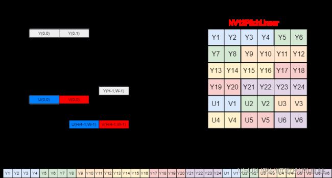
- 结构:在 NV12BlockLinear 中,Y 通道是连续存储的,接着是 UV 通道,UV 通道是交错存储的。与标准的 NV12 格式不同,NV12BlockLinear 在存储数据时会以块为单位进行重新排序,以提高内存访问的空间局部性。(图4-2)
- 应用:此格式经常在 GPU 或其他硬件加速环境中使用,因为它可以提高纹理过滤和内存访问的性能。
YUV422Packed_YUYV:
- 组织:YUYV 是 YUV422 格式的一种,其中 Y、U 和 V 的数据是交错存储的。
- 结构:每 4 个字节包含两个 Y 值和一个 U 值和一个 V 值。具体的存储顺序是:Y0、U、Y1、V
- 应用:由于它的交错结构,YUYV 格式经常用于某些摄像头和视频捕获设备
下面我们来看下这三种格式在内存中的存储结构和数据排布图:
W 表示图像的宽度,H 表示图像的高度,Stride 表示图像行的跨度,超出 W 部分为填充数据,主要目的是为了字节对齐,一般以 16 字节或者 32 字节对齐居多。
YUV 格式可以分为两大类:packed 和 planar
1. Pakced YUV 格式:
在 packed YUV 格式中,每个像素点的 Y,U,V 是连续交错存储的。常见的 packed YUV 格式包括 YUYV(例如 YUV422Packed_YUYV)以及 UYVY。
2. Planar YUV 格式:
Planar YUV 格式可以进一步细分为 纯 planar 格式和 semi-planar 格式
- 纯 planar 格式:在这种格式中,首先连续存储所有像素点的 Y 分量,然后连续存储所有像素点的 U 分量,最后连续存储所有像素点的 V 分量。常见的 纯 planar 格式包括 YV12 和 YU12
- Semi-planar 格式:在这种格式中,首先连续存储所有像素点的 Y 分量,然后在一个单独的区域中交错存储所有像素点的 U 和 V 分量。常见的 semi-planar 格式包括 NV12(例如 NV12PitchLinear、NV12BlockLinear) 和 NV21
从左侧的数据存储结构体可以看到 NV12 结构的 YUV 图像的高度(H)是分层次的,这个层次结构就被称为 Plane,即 NV12 在代码中用 Plane[0] 表示 Y 数据的起始地址,Plane[1] 表示 UV 数据的起始地址。而对于 YUYV 格式的 YUV 图像则是一个打包格式。
从右侧的数据排布图可以看到 NV12 结构的 YUV 图像都是 YUV4:2:0 采样即每四个 Y 共用一组 UV 分量,而 YUYV 格式的 YUV 图像则是 YUV4:2:2 采样即每两个 Y 共用一组 UV 分量。
4.2 Luma 和 Chroma
我们来聊下 YUV 图像中的 Luma 和 Chroma 是什么?
1. Luma
Luma 代表图像的亮度信息(Luminance),它是基于图像的灰度级别来定义的。在 YUV 色彩空间中,Luma 通常用 Y 表示。Luma 是从 RGB 色彩空间转换而来的。Luma 描述了图像的亮度,而不涉及颜色。
2. Chroma
Chroma 代表图像的色彩信息,包含 U 和 V 两个分量,它们描述了颜色的水平和垂直方向。与 Luma 不同,Chroma 可以进行子采样,这意味着 U 和 V 的分辨率可能比 Y 低。
通过将图像分解为 Luma(Y)和 Chroma(UV)分量,YUV 格式可以实现高效的颜色压缩。在很多视频编码和传输系统中,会对 chroma 分量进行下采样,因为人眼对亮度信息更敏感,而对色彩信息的敏感度较低。这使得我们可以在减少文件大小的同时,保持可接受的图像质量。
4.3 stride
下面我们聊聊图像中的 stride
在图像处理中,stride(有时也称为 pitch)是一个常见的概念,它表示从图像的一行到下一行的字节偏移量。
为什么我们需要 stride 呢?
1. 内存对齐:有时,为了提高内存访问的效率,系统需要按照特定的字节边界对数据进行对齐。在这种情况下,stride 可以用来确保每一行的开始都是对齐的。
2. 图像裁剪和 ROI:在进行图像裁剪或定义感兴趣区域 (ROI) 时,可以通过调整 stride 来方便地定位新的图像区域,而无需重新分配和复制图像数据。
3. 图像缩放和变换:在进行图像缩放或其他几何变换时,可以通过调整 stride 来改变图像的尺寸或方向。
在 YUVToRGB 库中对于 YUV422Packed_YUYV 格式,每两个 Y 值与一个 U 值和一个 V 值关联。因此,每两个像素(2 个 Y 值)需要 4 字节(YUYV)。所以图像的每一行需要 2 * width 字节,这就是为什么在代码中 YUYV 格式的 stride = 2 * width。
当我们在内存中遍历图像时,可能需要使用 stride 而不是图像的宽度来确定如何从一行移动到下一行。这尤其在处理与图像宽度不完全匹配的 stride 时很重要。
4.4 YUVToRGB的Python实现
下面的代码实现了利用 Python 对 YUVTORGB 库中 workspace/data 下的三个 YUV 图像转换成对应的 RGB 图像。(from chatGPT)
import cv2
import numpy as np

def convert_nv12_to_rgb(file_path, width, height):
    with open(file_path, 'rb') as f:
        y = np.frombuffer(f.read(width * height), dtype=np.uint8).reshape((height, width))
        uv = np.frombuffer(f.read(width * height // 2), dtype=np.uint8).reshape((height // 2, width))
        u = cv2.resize(uv[:, ::2], (width, height), interpolation=cv2.INTER_LINEAR)
        v = cv2.resize(uv[:, 1::2], (width, height), interpolation=cv2.INTER_LINEAR)
        return cv2.cvtColor(cv2.merge([y, u, v]), cv2.COLOR_YUV2BGR)

def convert_yuyv_to_rgb(file_path, width, height):
    with open(file_path, 'rb') as f:
        yuyv = np.frombuffer(f.read(width * height * 2), dtype=np.uint8).reshape((height, width, 2))
        y = yuyv[..., 0].reshape((height, width))
        u = yuyv[::, ::2, 1].reshape((height, width // 2))
        v = yuyv[::, 1::2, 1].reshape((height, width // 2))
        u = cv2.resize(u, (width, height), interpolation=cv2.INTER_LINEAR)
        v = cv2.resize(v, (width, height), interpolation=cv2.INTER_LINEAR)
        return cv2.cvtColor(cv2.merge([y, u, v]), cv2.COLOR_YUV2BGR)

# File paths and dimensions
yuv_files = [
    {"path": "nv12_1280x720.yuv", "width": 1280, "height": 720, "format": "NV12"},
    {"path": "nv12_3840x2160.yuv", "width": 3840, "height": 2160, "format": "NV12"},
    {"path": "yuyv_3840x2160_yuyv422.yuv", "width": 3840, "height": 2160, "format": "YUYV"}
]

# Convert and save YUV files to RGB images
for file_info in yuv_files:
    if file_info["format"] == "NV12":
        rgb_img = convert_nv12_to_rgb(file_info["path"], file_info["width"], file_info["height"])
    elif file_info["format"] == "YUYV":
        rgb_img = convert_yuyv_to_rgb(file_info["path"], file_info["width"], file_info["height"])
    output_path = file_info["path"].replace(".yuv", "_converted.png")
    cv2.imwrite(output_path, rgb_img)
总结
本篇博客简单记录并分享了博主在学习 YUVToRGB 库的各种知识,这篇本来应该是放在 cuOSD 库的前面,学岔了。这里博主主要是对 YUVToRGB 库中的代码进行了简单的分析,对 YUV 转换到 RGB 的流程有了基本的把握,首先是加载 YUV 图像,然后是在 GPU 上创建空白的 YUV 和 RGB 图像,接着将 YUV 图像从 CPU 拷贝到 GPU 上,最后调用核函数在 GPU 上将 YUV 图像数据转换为 RGB 图像数据。由于博主知识能力和精力有限,目前也只是分享了简单的使用,具体实现的细节需要各位看官自行了解了,感谢各位看到最后,创作不易,读后有收获的看官请帮忙⭐️
最后如果大家觉得这个 repo 对你有帮助的话,不妨帮忙点个 ⭐️ 支持一波!!!
参考
- YUVToRGB(CUDA Conversion)
- YOLOv5推理详解及预处理高性能实现
- YCbCr#ITU-R_BT.601_conversion
- 图像基础知识之YUV
