STM32F103串口通信USART小试牛刀
本文主要叙述了STM32F103芯片实现USART串口通信简介,通过库函数实现STM32F103芯片给电脑发送"Hello,world!"
实验环境:keil μVision、xCOM
文章目录
- 一、串口通信简介
- 二、创建工程
-
- 1.实验原理
- 2.代码实现
- 三、实验结果
- 四、总结
- 五、参考文献
一、串口通信简介
串口通信指串口按位(bit)发送和接收字节。尽管比特字节(byte)的串行通信慢,但串口可以在使用一根发送数据的同时用另一根线接收数据。常用协议包括RS-232(ANSI/EIA-232标准),一种IBM-PC及其兼容机上的串行连接标准。
说到RS-232协议,就不得不提RS232电平和TTL电平的区别。
rs232是个人计算机上的通讯接口之一,由电子工业协会(Electronic Industries AssociaTIon,EIA) 所制定的异步传输标准接口。通常 RS-232 接口以9个引脚 (DB-9) 或是25个引脚 (DB-25) 的型态出现,一般个人计算机上会有两组 RS-232 接口,分别称为 COM1 和 COM2。RS232的电平标准为+12V为逻辑负,-12为逻辑正,TTL电平为5V为逻辑正,0为逻辑负。TTL电平信号之所以被广泛使用,原因是因为:通常我们采用二进制来表示数据。而且规定,+5V等价于逻辑“1”,0V等价于逻辑“0”。这样的数据通信及电平规定方式,被称做TTL(晶体管-晶体管逻辑电平)信号系统。这是计算机处理器控制的设备内部各部分之间通信的标准技术。
在stm32中如何进行串口通信呢?这就要用到STM32的USAERT模块。
USART,英文全称——Universal Synchronous/Asychronous Receiver/Transmitter,即通用同步/异步串行收发模块,该接口是一个高度灵活的串行通信设备。通用同步异步收发器(USART)提供了一种灵活的方法与使用工业标准NRZ异步串行数据格式的外部设备之间进行全双工数据交换。在STM32中文参考手册第516页也做了比较详细的介绍。

二、创建工程
1.实验原理
打开数据手册,查看使用哪些引脚可以使用USART功能。不同芯片可能略微有所不同,但是一般A9和A10都可以实现串口的通信。

对于USART的实现,和GPIO类似,首先是时钟使能,然后是配置串口,最后是使能串口。使用串口时也需要将A9和A10设置为GPIO口,将A9设置为推挽复用模式,A10设置为浮空输入模式。在STM32固件库使用手册第344页,比较详细的介绍了通用同步异步收发器的相关库函数。
首先定义初始化GPIO和USART的结构体
/* 定义GPIO和USART的结构体 */
GPIO_InitTypeDef GPIO_InitStructure;
USART_InitTypeDef USART_InitStructure;
然后是时钟使能,这里USART1和GPIO都是RCC_APB2Periph时钟下的,所以时钟使能函数是一样的
/* 使能GPIO和USART的时钟 */
RCC_APB2PeriphClockCmd(RCC_APB2Periph_GPIOA,ENABLE);
RCC_APB2PeriphClockCmd(RCC_APB2Periph_USART1,ENABLE);
在stm32f10x.h中,可以找到USART_InitTypeDef结构体的定义。
typedef struct
{
  uint32_t USART_BaudRate;            /*!< This member configures the USART communication baud rate.
                                           The baud rate is computed using the following formula:
                                            - IntegerDivider = ((PCLKx) / (16 * (USART_InitStruct->USART_BaudRate)))
                                            - FractionalDivider = ((IntegerDivider - ((u32) IntegerDivider)) * 16) + 0.5 */

  uint16_t USART_WordLength;          /*!< Specifies the number of data bits transmitted or received in a frame.
                                           This parameter can be a value of @ref USART_Word_Length */

  uint16_t USART_StopBits;            /*!< Specifies the number of stop bits transmitted.
                                           This parameter can be a value of @ref USART_Stop_Bits */

  uint16_t USART_Parity;              /*!< Specifies the parity mode.
                                           This parameter can be a value of @ref USART_Parity
                                           @note When parity is enabled, the computed parity is inserted
                                                 at the MSB position of the transmitted data (9th bit when
                                                 the word length is set to 9 data bits; 8th bit when the
                                                 word length is set to 8 data bits). */

  uint16_t USART_Mode;                /*!< Specifies wether the Receive or Transmit mode is enabled or disabled.
                                           This parameter can be a value of @ref USART_Mode */

  uint16_t USART_HardwareFlowControl; /*!< Specifies wether the hardware flow control mode is enabled
                                           or disabled.
                                           This parameter can be a value of @ref USART_Hardware_Flow_Control */
} USART_InitTypeDef;
可以看到,我们需要设置波特率、字节长度、停止位、奇偶校验位、串口模式和是否使用硬件流控制。下面是配置和初始化程序代码
/* 配置串口 */
USART_InitStructure.USART_BaudRate=115200;										//波特率了设置为115200
USART_InitStructure.USART_HardwareFlowControl=USART_HardwareFlowControl_None;	//不使用硬件流控制
USART_InitStructure.USART_Mode=USART_Mode_Tx|USART_Mode_Rx;						//使能接收和发送
USART_InitStructure.USART_Parity=USART_Parity_No;								//不使用奇偶校验位
USART_InitStructure.USART_StopBits=USART_StopBits_1;							//1位停止位
USART_InitStructure.USART_WordLength=USART_WordLength_8b;						//字长设置为8位
USART_Init(USART1, &USART_InitStructure);										//初始化串口
最后使能串口
/* 使能串口 */
USART_Cmd(USART1,ENABLE);
除了使能串口,还需要配置GPIO口,并初始化GPIO,GPIO口的配置如下图
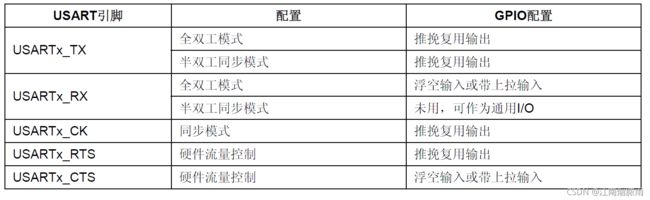
所以代码如下
/* 将USART TX(A9)的GPIO设置为推挽复用模式 */
GPIO_InitStructure.GPIO_Mode=GPIO_Mode_AF_PP;
GPIO_InitStructure.GPIO_Pin=GPIO_Pin_9;
GPIO_InitStructure.GPIO_Speed=GPIO_Speed_50MHz;
GPIO_Init(GPIOA,&GPIO_InitStructure);
/* 将USART RX(A10)的GPIO设置为浮空输入模式 */
GPIO_InitStructure.GPIO_Mode=GPIO_Mode_IN_FLOATING;
GPIO_InitStructure.GPIO_Pin=GPIO_Pin_10;
GPIO_Init(GPIOA,&GPIO_InitStructure);
对于本次实验还需要使单片机发送数据,所以需要编写下面的发送字节程序
/* 发送一个字节 */
void Usart_SendByte( USART_TypeDef * pUSARTx, uint8_t ch)
{
	/* 发送一个字节数据到USART */
	USART_SendData(pUSARTx,ch);

	/* 等待发送数据寄存器为空 */
	while (USART_GetFlagStatus(pUSARTx, USART_FLAG_TXE) == RESET);
}
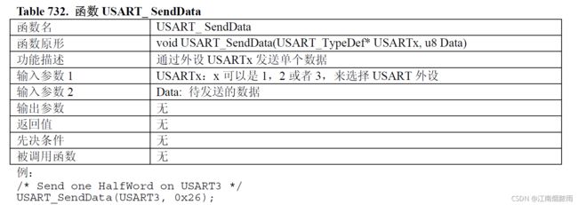
对于USART_SendData函数,在stm32f10x_usart.c文件中实现了
void USART_SendData(USART_TypeDef* USARTx, uint16_t Data)
{
  /* Check the parameters */
  assert_param(IS_USART_ALL_PERIPH(USARTx));
  assert_param(IS_USART_DATA(Data));

  /* Transmit Data */
  USARTx->DR = (Data & (uint16_t)0x01FF);
}
也可以在STM32固件库使用手册第354页中查找到
 实现了发送字节,同理可以实现发送字符串
/* 发送字符串 */
void Usart_SendString( USART_TypeDef * pUSARTx, char *str)
{
    unsigned int k=0;
  	do
    {
        Usart_SendByte( pUSARTx, *(str + k) );
      	k++;
  	} while(*(str + k)!='\0');
  	/* 等待发送完成 */
  	while(USART_GetFlagStatus(pUSARTx,USART_FLAG_TC)==RESET)
  	{}
}
2.代码实现
可以参考STM32F103点亮LED流水灯_江南烟脓雨的博客-CSDN博客这篇博客。在创建工程模板的基础上,添加usart.h和usart.c两个文件,并在Project目录下添加usart.c文件,在头文件中添加usart.h文件。
usart.h
#ifndef __USART_H
#define __USART_H
#include "stm32f10x.h"
#include "stdio.h"
void MyUSART_Init(void);
void Usart_SendByte( USART_TypeDef * pUSARTx, uint8_t ch);
void Usart_SendString( USART_TypeDef * pUSARTx, char *str);
#endif
usart.c
#include "usart.h"
void MyUSART_Init()
{
	/* 定义GPIO和USART的结构体 */
	GPIO_InitTypeDef GPIO_InitStructure;
	USART_InitTypeDef USART_InitStructure;
	/* 使能GPIO和USART的时钟 */
	RCC_APB2PeriphClockCmd(RCC_APB2Periph_GPIOA,ENABLE);
	RCC_APB2PeriphClockCmd(RCC_APB2Periph_USART1,ENABLE);
	/* 将USART TX(A9)的GPIO设置为推挽复用模式 */
	GPIO_InitStructure.GPIO_Mode=GPIO_Mode_AF_PP;
	GPIO_InitStructure.GPIO_Pin=GPIO_Pin_9;
	GPIO_InitStructure.GPIO_Speed=GPIO_Speed_50MHz;
	GPIO_Init(GPIOA,&GPIO_InitStructure);
	/* 将USART RX(A10)的GPIO设置为浮空输入模式 */
	GPIO_InitStructure.GPIO_Mode=GPIO_Mode_IN_FLOATING;
	GPIO_InitStructure.GPIO_Pin=GPIO_Pin_10;
	GPIO_Init(GPIOA,&GPIO_InitStructure);
	/* 配置串口 */
	USART_InitStructure.USART_BaudRate=115200;										//波特率了设置为115200
	USART_InitStructure.USART_HardwareFlowControl=USART_HardwareFlowControl_None;	//不使用硬件流控制
	USART_InitStructure.USART_Mode=USART_Mode_Tx|USART_Mode_Rx;						//使能接收和发送
	USART_InitStructure.USART_Parity=USART_Parity_No;								//不使用奇偶校验位
	USART_InitStructure.USART_StopBits=USART_StopBits_1;							//1位停止位
	USART_InitStructure.USART_WordLength=USART_WordLength_8b;						//字长设置为8位
	USART_Init(USART1, &USART_InitStructure);										//初始化串口
	/* 使能串口 */
	USART_Cmd(USART1,ENABLE);

}

/* 发送一个字节 */
void Usart_SendByte( USART_TypeDef * pUSARTx, uint8_t ch)
{
	/* 发送一个字节数据到USART */
	USART_SendData(pUSARTx,ch);

	/* 等待发送数据寄存器为空 */
	while (USART_GetFlagStatus(pUSARTx, USART_FLAG_TXE) == RESET);
}

/* 发送字符串 */
void Usart_SendString( USART_TypeDef * pUSARTx, char *str)
{
    unsigned int k=0;
    do
  	{
        Usart_SendByte( pUSARTx, *(str + k) );
      	k++;
  	} while(*(str + k)!='\0');
  	/* 等待发送完成 */
  	while(USART_GetFlagStatus(pUSARTx,USART_FLAG_TC)==RESET)
  	{}
}
main.c
#include "stm32f10x.h"
#include "usart.h"
u16 USART_RX_STA=0;							//接收状态标记
static u16 fac_ms = 0;
void delay_init(void);
void delay_ms(u16 nms);
int main(void)
{

	MyUSART_Init();
	delay_init();
	while(1)
	{
		Usart_SendString( USART1,"Hello,world!\r\n");
		delay_ms(500);
	}
}

void delay_init()
{
	SysTick_CLKSourceConfig(SysTick_CLKSource_HCLK_Div8);
	fac_ms = (u16)(SystemCoreClock/8000);
}

void delay_ms(u16 nms)
{
	u32 temp;
	SysTick->LOAD=(u32)nms*fac_ms;				//时间加载(SysTick->LOAD为24bit)
	SysTick->VAL =0x00;							//清空计数器
	SysTick->CTRL|=SysTick_CTRL_ENABLE_Msk ;	//开始倒数
	do
	{
		temp=SysTick->CTRL;
	}while((temp&0x01)&&!(temp&(1<<16)));		//等待时间到达
	SysTick->CTRL&=~SysTick_CTRL_ENABLE_Msk;	//关闭计数器
	SysTick->VAL =0X00;       					//清空计数器
}
这里加入了延时函数减少串口发送频率
三、实验结果
打开串口调试程序,这里我选择的是XCOM。打开软件后,选择串口,然后设置波特率、停止位、数据为和校验位,需要和前面程序中的相匹配。最后点击打开串口

可以看到,接收窗口已经显示接收信息
四、总结
本次实验简单的使用了USART功能,对于某些功能的实现还需要中断操作。
五、参考文献
串口通信协议_百度百科 (baidu.com)
rs232电平和TTL电平的区别 - 接口/总线/驱动 - 电子发烧友网 (elecfans.com)
USART_百度百科 (baidu.com)