开箱报告,Simulink Toolbox库模块使用指南(六)——S-Fuction模块(TLC)
文章目录
前言
Target Language Compiler(TLC)
C MEX S-Function模块
编写TLC文件
生成代码
Tips
分析和应用
总结
前言
见《开箱报告,Simulink Toolbox库模块使用指南(一)——powergui模块》
见《开箱报告,Simulink Toolbox库模块使用指南(二)——MATLAB Fuction模块》
见《开箱报告,Simulink Toolbox库模块使用指南(三)——Simscape 电路仿真模块》
见《开箱报告,Simulink Toolbox库模块使用指南(四)——S-Fuction模块》
见《开箱报告,Simulink Toolbox库模块使用指南(五)——S-Fuction模块(C MEX S-Function)》
Target Language Compiler(TLC)
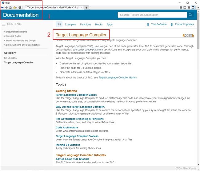
目标语言编译器(Target Language Compiler)代码生成器的重要组成部分。Mathworks官方Help对该部分内容的说明如下所示。
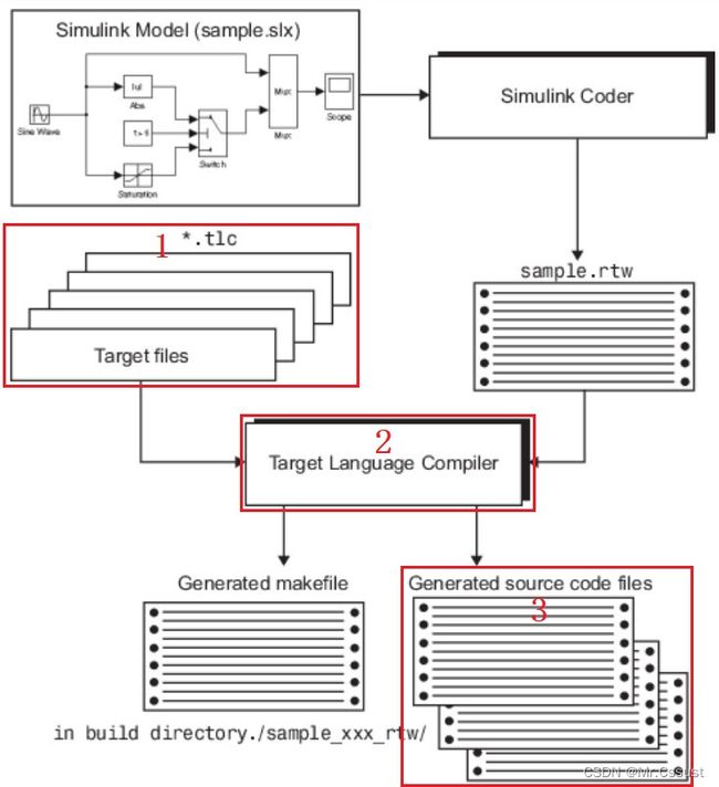
在使用Simulink自动生成代码时,Library中自带的模块可以顺利的生成代码,但是如果用户在Model中用到了自己开发的C MEX S-Function模块,Simulink就不知道这个模块如何生成代码了。TLC文件的作用就是,告诉Simulink自己想把C MEX S-Function模块生成一些什么样的代码,以及如何与Model中的其他内容互联融合。TLC及模型代码的生成过程如下图所示:
本文继续以DFT算法为例,介绍如何编写一个TLC文件,将C MEX S-Function模块生成代码。
C MEX S-Function模块
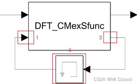
DFT算法的原理讲解和C MEX S-Function模块的开发在上一篇文章中已经完成了,见 《开箱报告,Simulink Toolbox库模块使用指南(五)——S-Fuction模块(C MEX S-Function)》。到这里仅仅是在Simulink中仿真时可以使用这样一个算法模块,本文是要把他生成C代码。由于算法中涉及了4个状态变量,对应到C语言中就要定义一组全局变量,这在TLC文件中实现会稍微麻烦一些。为了简化该过程,让大家更好地理解TLC,笔者对原有的C MEX S-Function模块进行了一些调整,将全局变量的定义放到了模块外面。如下图所示:
DFT_CMexSfunc.c中对应代码的调整如下:
//增加一个输入端口
if (!ssSetNumInputPorts(S, 2)) return;
ssSetInputPortWidth(S, 0, 1);
ssSetInputPortWidth(S, 1, 4); //新增的输入端口有4个信号

//增加一个输出端口
if (!ssSetNumOutputPorts(S, 2)) return;
ssSetOutputPortWidth(S, 0, 1);
ssSetOutputPortWidth(S, 1, 4); //新增的输处端口有4个信号
DFT_CMexSfunc.c调整后需要用mex命令重新编译,如下图所示:
编写TLC文件
在Model的Workspace文件夹下,新建一个DFT_CMexSfunc.tlc文件,编写tlc代码。写好后的完整内容如下,各部分代码的解释,以注释形式标注在对应位置。
%implements "DFT_CMexSfunc" "C"//与C MEX S-Function模块相对应

%% Function: Outputs
%function Outputs(block, system) Output//定义一个输出函数

%assign u = LibBlockInputSignal(0,"","",0)//获取输入信号
%assign u_count = LibBlockInputSignal(1,"","",0)
%assign u_t = LibBlockInputSignal(1,"","",1)
%assign u_cos_integ = LibBlockInputSignal(1,"","",2)
%assign u_sin_integ = LibBlockInputSignal(1,"","",3)

%assign y = LibBlockOutputSignal(0,"","",0) //获取输出信号
%assign y_count = LibBlockOutputSignal(1,"","",0)
%assign y_t = LibBlockOutputSignal(1,"","",1)
%assign y_cos_integ = LibBlockOutputSignal(1,"","",2)
%assign y_sin_integ = LibBlockOutputSignal(1,"","",3)

/%下面是要为C MEX S-Function模块生成的代码%/
if(% < 5e3)//为了降低TLC复杂度,将常量L的值5e3直接写出来
{
    % = % + %*cos(2*3.14 * 50*%);//将常量Freq的值50直接写出来
    % = % + %*sin(2*3.14 * 50*%);

    % = % + 1/10e3; //将常量Fs的值10e3直接写出来
    % = % + 1;
}
else if(% == 5e3)
{
    % = sqrt((%/L*2)^2 + (%/L*2)^2); //将过程变量real和imag用对应公式直接写出来
    % = % + 1;//避免无效运行消耗资源
}
else
{}

%endfunction//结束函数定义
DFT_CMexSfunc.tlc文件保存在对应的路径下即可,不需要做额外的编译操作。
生成代码
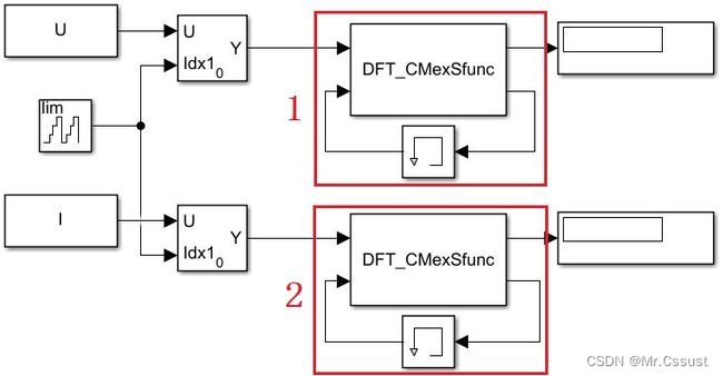
C MEX S-Function模块调整后对应的完整模型如下:
点击左侧的sfucdemo.c超链接,可以看到如下生成的代码,其中30行到140行是该模型主要功能的代码,40行到53行是与我们C MEX S-Function模块直接相关的代码。
File: sfucdemo.c
1	/*
2	 * sfucdemo.c
3	 *
4	 * Code generation for model "sfucdemo".
5	 *
6	 * Model version              : 1.45
7	 * Simulink Coder version : 9.4 (R2020b) 29-Jul-2020
8	 * C source code generated on : Sun Sep 10 14:44:22 2023
9	 *
10	 * Target selection: grt.tlc
11	 * Note: GRT includes extra infrastructure and instrumentation for prototyping
12	 * Embedded hardware selection: Intel->x86-64 (Windows64)
13	 * Code generation objectives: Unspecified
14	 * Validation result: Not run
15	 */
16
17	#include "sfucdemo.h"
18	#include "sfucdemo_private.h"
19
20	/* Block signals (default storage) */
21	B_sfucdemo_T sfucdemo_B;
22
23	/* Block states (default storage) */
24	DW_sfucdemo_T sfucdemo_DW;
25
26	/* Real-time model */
27	static RT_MODEL_sfucdemo_T sfucdemo_M_;
28	RT_MODEL_sfucdemo_T *const sfucdemo_M = &sfucdemo_M_;
29
30	/* Model step function */
31	void sfucdemo_step(void)
32	{
33	  /* Selector: '/Selector2' incorporates:
34	   *  Constant: '/Constant2'
35	   *  UnitDelay: '/Output'
36	   */
37	  sfucdemo_B.Selector2 =
38	    sfucdemo_ConstP.Constant2_Value[sfucdemo_DW.Output_DSTATE];
39
40	  /* S-Function (DFT_CMexSfunc): '/S-Function3' */
41	  if (sfucdemo_B.Memory[0] < 5e3) {
42	    sfucdemo_B.SFunction3_o2[2] = sfucdemo_B.Memory[2] + sfucdemo_B.Selector2*
43	      cos(2*3.14 * 50*sfucdemo_B.Memory[1]);
44	    sfucdemo_B.SFunction3_o2[3] = sfucdemo_B.Memory[3] + sfucdemo_B.Selector2*
45	      sin(2*3.14 * 50*sfucdemo_B.Memory[1]);
46	    sfucdemo_B.SFunction3_o2[1] = sfucdemo_B.Memory[1] + 1/10e3;
47	    sfucdemo_B.SFunction3_o2[0] = sfucdemo_B.Memory[0] + 1;
48	  } else if (sfucdemo_B.Memory[0] == 5e3) {
49	    sfucdemo_B.SFunction3_o1 = sqrt((sfucdemo_B.Memory[2]/L*2)^2 +
50	      (sfucdemo_B.Memory[3]/L*2)^2);
51	    sfucdemo_B.SFunction3_o2[0] = sfucdemo_B.Memory[0] + 1;
52	  } else {
53	  }
54
55	  /* Selector: '/Selector3' incorporates:
56	   *  Constant: '/Constant3'
57	   *  UnitDelay: '/Output'
58	   */
59	  sfucdemo_B.Selector3 =
60	    sfucdemo_ConstP.Constant3_Value[sfucdemo_DW.Output_DSTATE];
61
62	  /* S-Function (DFT_CMexSfunc): '/S-Function4' */
63	  if (sfucdemo_B.Memory1[0] < 5e3) {
64	    sfucdemo_B.SFunction4_o2[2] = sfucdemo_B.Memory1[2] + sfucdemo_B.Selector3*
65	      cos(2*3.14 * 50*sfucdemo_B.Memory1[1]);
66	    sfucdemo_B.SFunction4_o2[3] = sfucdemo_B.Memory1[3] + sfucdemo_B.Selector3*
67	      sin(2*3.14 * 50*sfucdemo_B.Memory1[1]);
68	    sfucdemo_B.SFunction4_o2[1] = sfucdemo_B.Memory1[1] + 1/10e3;
69	    sfucdemo_B.SFunction4_o2[0] = sfucdemo_B.Memory1[0] + 1;
70	  } else if (sfucdemo_B.Memory1[0] == 5e3) {
71	    sfucdemo_B.SFunction4_o1 = sqrt((sfucdemo_B.Memory1[2]/L*2)^2 +
72	      (sfucdemo_B.Memory1[3]/L*2)^2);
73	    sfucdemo_B.SFunction4_o2[0] = sfucdemo_B.Memory1[0] + 1;
74	  } else {
75	  }
76
77	  /* Switch: '/FixPt Switch' incorporates:
78	   *  Constant: '/FixPt Constant'
79	   *  Sum: '/FixPt Sum1'
80	   *  UnitDelay: '/Output'
81	   */
82	  if ((uint16_T)(sfucdemo_DW.Output_DSTATE + 1U) > 4999) {
83	    /* Update for UnitDelay: '/Output' incorporates:
84	     *  Constant: '/Constant'
85	     */
86	    sfucdemo_DW.Output_DSTATE = 0U;
87	  } else {
88	    /* Update for UnitDelay: '/Output' */
89	    sfucdemo_DW.Output_DSTATE++;
90	  }
91
92	  /* End of Switch: '/FixPt Switch' */
93
94	  /* Memory: '/Memory' */
95	  sfucdemo_B.Memory[0] = sfucdemo_DW.Memory_PreviousInput[0];
96
97	  /* Memory: '/Memory1' */
98	  sfucdemo_B.Memory1[0] = sfucdemo_DW.Memory1_PreviousInput[0];
99
100	  /* Update for Memory: '/Memory' */
101	  sfucdemo_DW.Memory_PreviousInput[0] = sfucdemo_B.SFunction3_o2[0];
102
103	  /* Update for Memory: '/Memory1' */
104	  sfucdemo_DW.Memory1_PreviousInput[0] = sfucdemo_B.SFunction4_o2[0];
105
106	  /* Memory: '/Memory' */
107	  sfucdemo_B.Memory[1] = sfucdemo_DW.Memory_PreviousInput[1];
108
109	  /* Memory: '/Memory1' */
110	  sfucdemo_B.Memory1[1] = sfucdemo_DW.Memory1_PreviousInput[1];
111
112	  /* Update for Memory: '/Memory' */
113	  sfucdemo_DW.Memory_PreviousInput[1] = sfucdemo_B.SFunction3_o2[1];
114
115	  /* Update for Memory: '/Memory1' */
116	  sfucdemo_DW.Memory1_PreviousInput[1] = sfucdemo_B.SFunction4_o2[1];
117
118	  /* Memory: '/Memory' */
119	  sfucdemo_B.Memory[2] = sfucdemo_DW.Memory_PreviousInput[2];
120
121	  /* Memory: '/Memory1' */
122	  sfucdemo_B.Memory1[2] = sfucdemo_DW.Memory1_PreviousInput[2];
123
124	  /* Update for Memory: '/Memory' */
125	  sfucdemo_DW.Memory_PreviousInput[2] = sfucdemo_B.SFunction3_o2[2];
126
127	  /* Update for Memory: '/Memory1' */
128	  sfucdemo_DW.Memory1_PreviousInput[2] = sfucdemo_B.SFunction4_o2[2];
129
130	  /* Memory: '/Memory' */
131	  sfucdemo_B.Memory[3] = sfucdemo_DW.Memory_PreviousInput[3];
132
133	  /* Memory: '/Memory1' */
134	  sfucdemo_B.Memory1[3] = sfucdemo_DW.Memory1_PreviousInput[3];
135
136	  /* Update for Memory: '/Memory' */
137	  sfucdemo_DW.Memory_PreviousInput[3] = sfucdemo_B.SFunction3_o2[3];
138
139	  /* Update for Memory: '/Memory1' */
140	  sfucdemo_DW.Memory1_PreviousInput[3] = sfucdemo_B.SFunction4_o2[3];
141
142	  /* Matfile logging */
143	  rt_UpdateTXYLogVars(sfucdemo_M->rtwLogInfo, (&sfucdemo_M->Timing.taskTime0));
144
145	  /* signal main to stop simulation */
146	  {                                    /* Sample time: [0.001s, 0.0s] */
147	    if ((rtmGetTFinal(sfucdemo_M)!=-1) &&
148	        !((rtmGetTFinal(sfucdemo_M)-sfucdemo_M->Timing.taskTime0) >
149	          sfucdemo_M->Timing.taskTime0 * (DBL_EPSILON))) {
150	      rtmSetErrorStatus(sfucdemo_M, "Simulation finished");
151	    }
152	  }
153
154	  /* Update absolute time for base rate */
155	  /* The "clockTick0" counts the number of times the code of this task has
156	   * been executed. The absolute time is the multiplication of "clockTick0"
157	   * and "Timing.stepSize0". Size of "clockTick0" ensures timer will not
158	   * overflow during the application lifespan selected.
159	   * Timer of this task consists of two 32 bit unsigned integers.
160	   * The two integers represent the low bits Timing.clockTick0 and the high bits
161	   * Timing.clockTickH0. When the low bit overflows to 0, the high bits increment.
162	   */
163	  if (!(++sfucdemo_M->Timing.clockTick0)) {
164	    ++sfucdemo_M->Timing.clockTickH0;
165	  }
166
167	  sfucdemo_M->Timing.taskTime0 = sfucdemo_M->Timing.clockTick0 *
168	    sfucdemo_M->Timing.stepSize0 + sfucdemo_M->Timing.clockTickH0 *
169	    sfucdemo_M->Timing.stepSize0 * 4294967296.0;
170	}
171
172	/* Model initialize function */
173	void sfucdemo_initialize(void)
174	{
175	  /* Registration code */
176
177	  /* initialize non-finites */
178	  rt_InitInfAndNaN(sizeof(real_T));
179
180	  /* initialize real-time model */
181	  (void) memset((void *)sfucdemo_M, 0,
182	                sizeof(RT_MODEL_sfucdemo_T));
183	  rtmSetTFinal(sfucdemo_M, 10.0);
184	  sfucdemo_M->Timing.stepSize0 = 0.001;
185
186	  /* Setup for data logging */
187	  {
188	    static RTWLogInfo rt_DataLoggingInfo;
189	    rt_DataLoggingInfo.loggingInterval = NULL;
190	    sfucdemo_M->rtwLogInfo = &rt_DataLoggingInfo;
191	  }
192
193	  /* Setup for data logging */
194	  {
195	    rtliSetLogXSignalInfo(sfucdemo_M->rtwLogInfo, (NULL));
196	    rtliSetLogXSignalPtrs(sfucdemo_M->rtwLogInfo, (NULL));
197	    rtliSetLogT(sfucdemo_M->rtwLogInfo, "tout");
198	    rtliSetLogX(sfucdemo_M->rtwLogInfo, "");
199	    rtliSetLogXFinal(sfucdemo_M->rtwLogInfo, "");
200	    rtliSetLogVarNameModifier(sfucdemo_M->rtwLogInfo, "rt_");
201	    rtliSetLogFormat(sfucdemo_M->rtwLogInfo, 0);
202	    rtliSetLogMaxRows(sfucdemo_M->rtwLogInfo, 0);
203	    rtliSetLogDecimation(sfucdemo_M->rtwLogInfo, 1);
204	    rtliSetLogY(sfucdemo_M->rtwLogInfo, "");
205	    rtliSetLogYSignalInfo(sfucdemo_M->rtwLogInfo, (NULL));
206	    rtliSetLogYSignalPtrs(sfucdemo_M->rtwLogInfo, (NULL));
207	  }
208
209	  /* block I/O */
210	  (void) memset(((void *) &sfucdemo_B), 0,
211	                sizeof(B_sfucdemo_T));
212
213	  /* states (dwork) */
214	  (void) memset((void *)&sfucdemo_DW, 0,
215	                sizeof(DW_sfucdemo_T));
216
217	  /* Matfile logging */
218	  rt_StartDataLoggingWithStartTime(sfucdemo_M->rtwLogInfo, 0.0, rtmGetTFinal
219	    (sfucdemo_M), sfucdemo_M->Timing.stepSize0, (&rtmGetErrorStatus(sfucdemo_M)));
220
221	  /* InitializeConditions for UnitDelay: '/Output' */
222	  sfucdemo_DW.Output_DSTATE = 0U;
223
224	  /* InitializeConditions for Memory: '/Memory' */
225	  sfucdemo_DW.Memory_PreviousInput[0] = 0.0;
226
227	  /* InitializeConditions for Memory: '/Memory1' */
228	  sfucdemo_DW.Memory1_PreviousInput[0] = 0.0;
229
230	  /* InitializeConditions for Memory: '/Memory' */
231	  sfucdemo_DW.Memory_PreviousInput[1] = 0.0;
232
233	  /* InitializeConditions for Memory: '/Memory1' */
234	  sfucdemo_DW.Memory1_PreviousInput[1] = 0.0;
235
236	  /* InitializeConditions for Memory: '/Memory' */
237	  sfucdemo_DW.Memory_PreviousInput[2] = 0.0;
238
239	  /* InitializeConditions for Memory: '/Memory1' */
240	  sfucdemo_DW.Memory1_PreviousInput[2] = 0.0;
241
242	  /* InitializeConditions for Memory: '/Memory' */
243	  sfucdemo_DW.Memory_PreviousInput[3] = 0.0;
244
245	  /* InitializeConditions for Memory: '/Memory1' */
246	  sfucdemo_DW.Memory1_PreviousInput[3] = 0.0;
247	}
248
249	/* Model terminate function */
250	void sfucdemo_terminate(void)
251	{
252	  /* (no terminate code required) */
253	}
254
人工检查上述自动生成的C代码,可以实现该Simulink模型设计的功能。
至此,可以证明该TLC文件可以较好地生成C MEX S-Fuction模块的自动代码。
Tips
TLC的特殊性在于,它本身是一种编程语言,具有文本类编程语言的大部分特点,同时它要实现的功能又是控制C或C++另一种文本语言代码的生成,所以TLC的开发必须熟练掌握它特有的语法结构,常见的一些基础语法如下。
1、%,TLC指令开始的标志符。
2、%implements,一个模块的TLC文件要执行的第一条指令,不可省略。
3、%function,声明一个函数,要配合%endfunction使用。
4、%assign,创建变量。
5、函数LibBlockInputSignal(portIdx, "","",sigIdx),返回模块的输入信号,portIdx和sigIdx都从0开始计数。
6、函数LibBlockOutputSignal(portIdx, "","",sigIdx),返回模块的输出信号。
7、函数LibBlockParameterValue(param, elIdx),返回模块的参数值。
8、<>,TLC表达式的开始和结束。
9、%%和/% %/,注释。
分析和应用
本文上述内容中看到,TLC实现了C MEX S-Fuction模块的代码生成,但是进一步仔细研究发现,Library中自带的模块的代码生成也是由TLC实现的,甚至生成代码的总体结构也是由TLC实现的,这些模块的TLC文件就存放在Matlab的系统路径ProgramFiles\Matlab2020b\rtw\c\tlc下。
所以说Simulink的自动代码生成过程,并不是完全固定死的,当我们有特定需求时,可以通过调整TLC文件的内容来实现的。这样就给了代码开发工程师们在代码生成方面的灵活度和自由度,为Simulink的自动代码生成提供了无限可能。
总结
以上就是本人在使用TLC时,一些个人理解和分析的总结,首先介绍了TLC的背景知识,然后展示它的使用方法,最后分析了该模块的特点和适用场景。
后续还会分享另外几个最近总结的Simulink Toolbox库模块,欢迎评论区留言、点赞、收藏和关注,这些鼓励和支持都将成文本人持续分享的动力。
另外,上述例程使用的Demo工程,可以到笔者的主页查找和下载。
版权声明,原创文章,转载和引用请注明出处和链接,侵权必究!


