《Qt-OpenGL系列编程》课程学习记录(8):绘制一个长方体
要绘制一个长方体,每一面都是图片。
为了简便,就不使用EBO了。
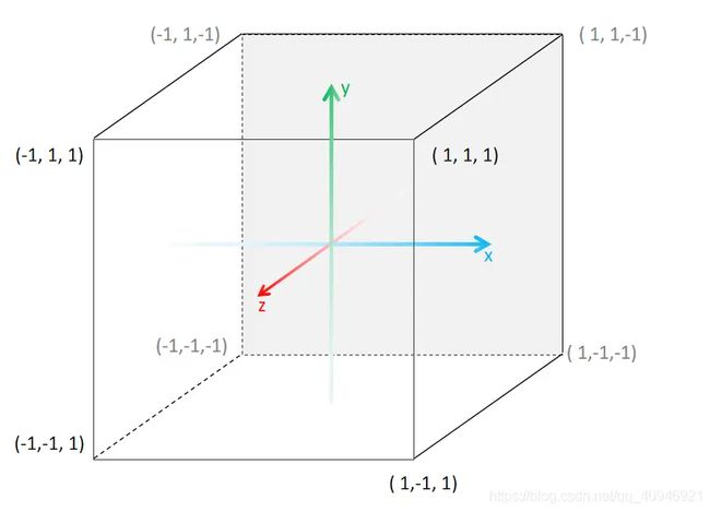
前面的内容是绘制一个面的,但是长方体有六个面。其实方法也是一样的,根据这个图设置坐标:
float vertices[] =
{
    //位置坐标              纹理坐标
    -0.5f, -0.5f, -0.5f,    0.0f, 0.0f,
     0.5f, -0.5f, -0.5f,    1.0f, 0.0f,
     0.5f, 0.5f, -0.5f,     1.0f, 1.0f,
     0.5f, 0.5f, -0.5f,     1.0f, 1.0f,
    -0.5f, 0.5f, -0.5f,     0.0f, 1.0f,
    -0.5f, -0.5f, -0.5f,    0.0f, 0.0f,

    -0.5f, -0.5f, 0.5f,     0.0f, 0.0f,
    0.5f, -0.5f, 0.5f,      1.0f, 0.0f,
    0.5f, 0.5f, 0.5f,       1.0f, 1.0f,
    0.5f, 0.5f, 0.5f,       1.0f, 1.0f,
    -0.5f, 0.5f, 0.5f,      0.0f, 1.0f,
    -0.5f, -0.5f, 0.5f,     0.0f, 0.0f,

    -0.5f, 0.5f, 0.5f,      1.0f, 0.0f,
    -0.5f, 0.5f, -0.5f,     1.0f, 1.0f,
    -0.5f, -0.5f, -0.5f,    0.0f, 1.0f,
    -0.5f, -0.5f, -0.5f,    0.0f, 1.0f,
    -0.5f, -0.5f, 0.5f,     0.0f, 0.0f,
    -0.5f, 0.5f, 0.5f,      1.0f, 0.0f,

     0.5f, 0.5f, 0.5f,      1.0f, 0.0f,
     0.5f, 0.5f, -0.5f,     1.0f, 1.0f,
     0.5f, -0.5f, -0.5f,    0.0f, 1.0f,
     0.5f, -0.5f, -0.5f,    0.0f, 1.0f,
     0.5f, -0.5f, 0.5f,     0.0f, 0.0f,
     0.5f, 0.5f, 0.5f,      1.0f, 0.0f,

    -0.5f, -0.5f, -0.5f,    0.0f, 1.0f,
     0.5f, -0.5f, -0.5f,    1.0f, 1.0f,
     0.5f, -0.5f, 0.5f,     1.0f, 0.0f,
     0.5f, -0.5f, 0.5f,     1.0f, 0.0f,
    -0.5f, -0.5f, 0.5f,     0.0f, 0.0f,
    -0.5f, -0.5f, -0.5f,    0.0f, 1.0f,

    -0.5f, 0.5f, -0.5f,     0.0f, 1.0f,
     0.5f, 0.5f, -0.5f,     1.0f, 1.0f,
     0.5f, 0.5f, 0.5f,      1.0f, 0.0f,
     0.5f, 0.5f, 0.5f,      1.0f, 0.0f,
    -0.5f, 0.5f, 0.5f,      0.0f, 0.0f,
    -0.5f, 0.5f, -0.5f,     0.0f, 1.0f
};
//顶点着色器
#version 450 core
layout(location = 0) in vec3 aPos;
layout(location = 1) in vec2 aTexCord;
out vec2 TexCord;
void main(){
gl_Position = vec4(aPos, 1.0f);
TexCord=aTexCord;
}//片段着色器
#version 450 core
out vec4 FragColor;
in vec2 TexCord;
uniform sampler2D textureWall;
void main()
{
FragColor = texture(textureWall,TexCord);
}#include "widget.h"
#include
#include
#include
#include
unsigned int VBO, VAO;
Widget::Widget(QWidget *parent) : QOpenGLWidget(parent)
{
}
Widget::~Widget()
{
makeCurrent();
glDeleteBuffers(1,&VBO);
glDeleteVertexArrays(1,&VAO);
doneCurrent();
}
void Widget::initializeGL()
{
initializeOpenGLFunctions();
glGenVertexArrays(1, &VAO);
glGenBuffers(1, &VBO);
glBindVertexArray(VAO);
glBindBuffer(GL_ARRAY_BUFFER, VBO);
glBufferData(GL_ARRAY_BUFFER, sizeof(vertices), vertices, GL_STATIC_DRAW);
glVertexAttribPointer(0, 3, GL_FLOAT, GL_FALSE, 5 * sizeof(float), nullptr);
glEnableVertexAttribArray(0);
glVertexAttribPointer(1, 2, GL_FLOAT, GL_FALSE, 5 * sizeof(float), (void*)(3 * sizeof(float)));
glEnableVertexAttribArray(1);
glBindBuffer(GL_ARRAY_BUFFER, 0);
shaderProgram.addShaderFromSourceFile(QOpenGLShader::Vertex,":/shapes.vert");
shaderProgram.addShaderFromSourceFile(QOpenGLShader::Fragment,":/shapes.frag");
if(!shaderProgram.link())
qDebug()<<"着色器程序编译错误信息:"<bind(0);
glDrawArrays(GL_TRIANGLES,0,36);
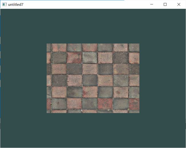
} 结果是这样的:
因为我们是从一个面的中央观察一个立方体,只能看到它的一个面。
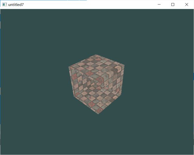
要使它看起来有立方体的感觉要进行一些操作。
一些概念
模型矩阵(model)
定义缩放,旋转,平移的操作。
视图矩阵(view)
模拟一个摄像机的镜头,以便可以在3D空间中的某个位置去观察另一个位置。
投影矩阵(projection)
负责使看到的画面符合近大远小的透视规律,并且保证无论窗口的宽高比是多少,看到的画面都不会再变形。
顶点位置乘以这三个矩阵即可得到立体的效果。
//顶点着色器
#version 450 core
layout(location = 0) in vec3 aPos;
layout(location = 1) in vec2 aTexCord;
out vec2 TexCord;
uniform mat4 model;
uniform mat4 view;
uniform mat4 projection;
void main()
{
    gl_Position = projection*view*model*vec4(aPos, 1.0f);
    TexCord = aTexCord;
}
#include "widget.h"
#include
#include
#include
#include
unsigned int VBO, VAO;
float vertices[] =
{
//位置坐标 纹理坐标
-0.5f, -0.5f, -0.5f, 0.0f, 0.0f,
0.5f, -0.5f, -0.5f, 1.0f, 0.0f,
0.5f, 0.5f, -0.5f, 1.0f, 1.0f,
0.5f, 0.5f, -0.5f, 1.0f, 1.0f,
-0.5f, 0.5f, -0.5f, 0.0f, 1.0f,
-0.5f, -0.5f, -0.5f, 0.0f, 0.0f,
-0.5f, -0.5f, 0.5f, 0.0f, 0.0f,
0.5f, -0.5f, 0.5f, 1.0f, 0.0f,
0.5f, 0.5f, 0.5f, 1.0f, 1.0f,
0.5f, 0.5f, 0.5f, 1.0f, 1.0f,
-0.5f, 0.5f, 0.5f, 0.0f, 1.0f,
-0.5f, -0.5f, 0.5f, 0.0f, 0.0f,
-0.5f, 0.5f, 0.5f, 1.0f, 0.0f,
-0.5f, 0.5f, -0.5f, 1.0f, 1.0f,
-0.5f, -0.5f, -0.5f, 0.0f, 1.0f,
-0.5f, -0.5f, -0.5f, 0.0f, 1.0f,
-0.5f, -0.5f, 0.5f, 0.0f, 0.0f,
-0.5f, 0.5f, 0.5f, 1.0f, 0.0f,
0.5f, 0.5f, 0.5f, 1.0f, 0.0f,
0.5f, 0.5f, -0.5f, 1.0f, 1.0f,
0.5f, -0.5f, -0.5f, 0.0f, 1.0f,
0.5f, -0.5f, -0.5f, 0.0f, 1.0f,
0.5f, -0.5f, 0.5f, 0.0f, 0.0f,
0.5f, 0.5f, 0.5f, 1.0f, 0.0f,
-0.5f, -0.5f, -0.5f, 0.0f, 1.0f,
0.5f, -0.5f, -0.5f, 1.0f, 1.0f,
0.5f, -0.5f, 0.5f, 1.0f, 0.0f,
0.5f, -0.5f, 0.5f, 1.0f, 0.0f,
-0.5f, -0.5f, 0.5f, 0.0f, 0.0f,
-0.5f, -0.5f, -0.5f, 0.0f, 1.0f,
-0.5f, 0.5f, -0.5f, 0.0f, 1.0f,
0.5f, 0.5f, -0.5f, 1.0f, 1.0f,
0.5f, 0.5f, 0.5f, 1.0f, 0.0f,
0.5f, 0.5f, 0.5f, 1.0f, 0.0f,
-0.5f, 0.5f, 0.5f, 0.0f, 0.0f,
-0.5f, 0.5f, -0.5f, 0.0f, 1.0f
};
QVector cubePositions =
{
QVector3D( 0.0f, 0.0f, 0.0f),
//QVector3D( 2.0f, 5.0f, -15.0f),
//QVector3D(-1.5f, -2.2f, -2.5f),
//QVector3D(-3.8f, -2.0f, -12.3f),
//QVector3D( 2.4f, -0.4f, -3.5f),
//QVector3D(-1.7f, 3.0f, -7.5f),
//QVector3D( 1.3f, -2.0f, -2.5f),
//QVector3D( 1.5f, 2.0f, -2.5f),
//QVector3D( 1.5f, 0.2f, -1.5f),
//QVector3D(-1.3f, 1.0f, -1.5f)
};
Widget::Widget(QWidget *parent) : QOpenGLWidget(parent)
{
}
Widget::~Widget()
{
makeCurrent();
glDeleteBuffers(1,&VBO);
glDeleteVertexArrays(1,&VAO);
doneCurrent();
}
void Widget::initializeGL()
{
initializeOpenGLFunctions();
glGenVertexArrays(1, &VAO);
glGenBuffers(1, &VBO);
glBindVertexArray(VAO);
glBindBuffer(GL_ARRAY_BUFFER, VBO);
glBufferData(GL_ARRAY_BUFFER, sizeof(vertices), vertices, GL_STATIC_DRAW);
glVertexAttribPointer(0, 3, GL_FLOAT, GL_FALSE, 5 * sizeof(float), nullptr);
glEnableVertexAttribArray(0);
glVertexAttribPointer(1, 2, GL_FLOAT, GL_FALSE, 5 * sizeof(float), (void*)(3 * sizeof(float)));
glEnableVertexAttribArray(1);
glBindBuffer(GL_ARRAY_BUFFER, 0);
shaderProgram.addShaderFromSourceFile(QOpenGLShader::Vertex,":/shapes.vert");
shaderProgram.addShaderFromSourceFile(QOpenGLShader::Fragment,":/shapes.frag");
if(!shaderProgram.link())
qDebug()<<"着色器程序编译错误信息:"<bind(0);
for (const QVector3D & item : cubePositions)
{
//模型矩阵
QMatrix4x4 model;
model.setToIdentity();
model.translate(item);//平移
model.rotate(time, 1.0f, 1.0f, 0.5f);//旋转 该矩阵将坐标绕矢量 (x, y, z) 旋转angle度
model.scale(1.0f);//缩放
shaderProgram.setUniformValue("model", model);
glDrawArrays(GL_TRIANGLES,0,36);
}
} 加上一个定时器:
    auto timer = new QTimer(this);
    connect(timer,&QTimer::timeout,this,[this]{update();});
    timer->start(100);
绘制多个:
QVector cubePositions =
{
    QVector3D( 0.0f, 0.0f, 0.0f),
    QVector3D( 2.0f, 5.0f, -15.0f),
    QVector3D(-1.5f, -2.2f, -2.5f),
    QVector3D(-3.8f, -2.0f, -12.3f),
    QVector3D( 2.4f, -0.4f, -3.5f),
    QVector3D(-1.7f, 3.0f, -7.5f),
    QVector3D( 1.3f, -2.0f, -2.5f),
    QVector3D( 1.5f, 2.0f, -2.5f),
    QVector3D( 1.5f, 0.2f, -1.5f),
    QVector3D(-1.3f, 1.0f, -1.5f)
}; 

