【ROS学习笔记17】ROS常用仿真组件URDF集成Gazebo
【ROS学习笔记17】ROS常用仿真组件URDF集成Gazebo
文章目录
- 【ROS学习笔记17】ROS常用仿真组件URDF集成Gazebo
-
- 前言
- 1. URDF集成Gazebo
-
- 1.1 URDF与Gazebo基本集成流程
- 1.2 URDF集成Gazebo相关设置
- 1.3 URDF集成Gazebo实操
- 1.4 Gazebo仿真环境搭建
- 2. URDF、Gazebo、Rviz综合应用
-
- 2.1 机器人运动控制及里程计信息显示
- 2.2 雷达信息仿真及显示
- 2.3 摄像头信息仿真及显示
- 2.4 kinect信息仿真及显示
- Reference
写在前面,本系列笔记参考的是AutoLabor的教程,具体项目地址在 这里
前言
1. URDF集成Gazebo
1.1 URDF与Gazebo基本集成流程
URDF 与 Gazebo 集成流程与 Rviz 实现类似,主要步骤如下:
- 创建功能包,导入依赖项
- 编写 URDF 或 Xacro 文件
- 启动 Gazebo 并显示机器人模型
1.创建功能包
创建新功能包,导入依赖包:
urdf、xacro、gazebo_ros、gazebo_ros_control、gazebo_plugins
2.编写URDF文件
<robot name="mycar">
    <link name="base_link">
        <visual>
            <geometry>
                <box size="0.5 0.2 0.1" />
            geometry>
            <origin xyz="0.0 0.0 0.0" rpy="0.0 0.0 0.0" />
            <material name="yellow">
                <color rgba="0.5 0.3 0.0 1" />
            material>
        visual>
        <collision>
            <geometry>
                <box size="0.5 0.2 0.1" />
            geometry>
            <origin xyz="0.0 0.0 0.0" rpy="0.0 0.0 0.0" />
        collision>
        <inertial>
            <origin xyz="0 0 0" />
            <mass value="6" />
            <inertia ixx="1" ixy="0" ixz="0" iyy="1" iyz="0" izz="1" />
        inertial>
    link>
    <gazebo reference="base_link">
        <material>Gazebo/Blackmaterial>
    gazebo>

robot>
注意, 当 URDF 需要与 Gazebo 集成时,和 Rviz 有明显区别:
1.必须使用 collision 标签,因为既然是仿真环境,那么必然涉及到碰撞检测,collision 提供碰撞检测的依据。
2.必须使用 inertial 标签,此标签标注了当前机器人某个刚体部分的惯性矩阵,用于一些力学相关的仿真计算。
3.颜色设置,也需要重新使用 gazebo 标签标注,因为之前的颜色设置为了方便调试包含透明度,仿真环境下没有此选项。
3.启动Gazebo并显示模型
launch 文件实现:
<launch>


    <param name="robot_description" textfile="$(find demo02_urdf_gazebo)/urdf/urdf01_helloworld.urdf" />


    <include file="$(find gazebo_ros)/launch/empty_world.launch" />


    <node pkg="gazebo_ros" type="spawn_model" name="model" args="-urdf -model mycar -param robot_description"  />
launch>
代码解释:
<include file="$(find gazebo_ros)/launch/empty_world.launch" />

<node pkg="gazebo_ros" type="spawn_model" name="model" args="-urdf -model mycar -param robot_description"  />
示例结果:

1.2 URDF集成Gazebo相关设置
较之于 rviz,gazebo在集成 URDF 时,需要做些许修改,比如:必须添加 collision 碰撞属性相关参数、必须添加 inertial 惯性矩阵相关参数,另外,如果直接移植 Rviz 中机器人的颜色设置是没有显示的,颜色设置也必须做相应的变更。
1.collision
如果机器人link是标准的几何体形状,和link的 visual 属性设置一致即可。
2.inertial
惯性矩阵的设置需要结合link的质量与外形参数动态生成,标准的球体、圆柱与立方体的惯性矩阵公式如下(已经封装为 xacro 实现):
球体惯性矩阵
    <xacro:macro name="sphere_inertial_matrix" params="m r">
        <inertial>
            <mass value="${m}" />
            <inertia ixx="${2*m*r*r/5}" ixy="0" ixz="0"
                iyy="${2*m*r*r/5}" iyz="0"
                izz="${2*m*r*r/5}" />
        inertial>
    xacro:macro>
圆柱惯性矩阵
<xacro:macro name="cylinder_inertial_matrix" params="m r h">
        <inertial>
            <mass value="${m}" />
            <inertia ixx="${m*(3*r*r+h*h)/12}" ixy = "0" ixz = "0"
                iyy="${m*(3*r*r+h*h)/12}" iyz = "0"
                izz="${m*r*r/2}" />
        inertial>
    xacro:macro>
立方体惯性矩阵
 <xacro:macro name="Box_inertial_matrix" params="m l w h">
       <inertial>
               <mass value="${m}" />
               <inertia ixx="${m*(h*h + l*l)/12}" ixy = "0" ixz = "0"
                   iyy="${m*(w*w + l*l)/12}" iyz= "0"
                   izz="${m*(w*w + h*h)/12}" />
       inertial>
   xacro:macro>
需要注意的是,原则上,除了 base_footprint 外,机器人的每个刚体部分都需要设置惯性矩阵,且惯性矩阵必须经计算得出,如果随意定义刚体部分的惯性矩阵,那么可能会导致机器人在 Gazebo 中出现抖动,移动等现象。
3.颜色设置
在 gazebo 中显示 link 的颜色,必须要使用指定的标签:
<gazebo reference="link节点名称">
     <material>Gazebo/Bluematerial>
gazebo>
**PS:**material 标签中,设置的值区分大小写,颜色可以设置为 Red Blue Green Black …
示例结果:

1.3 URDF集成Gazebo实操
需求描述:
将之前的机器人模型(xacro版)显示在 gazebo 中
结果演示:

实现流程:
- 需要编写封装惯性矩阵算法的 xacro 文件
- 为机器人模型中的每一个 link 添加 collision 和 inertial 标签,并且重置颜色属性
- 在 launch 文件中启动 gazebo 并添加机器人模型
1.编写封装惯性矩阵算法的 xacro 文件
<robot name="base" xmlns:xacro="http://wiki.ros.org/xacro">

    <xacro:macro name="sphere_inertial_matrix" params="m r">
        <inertial>
            <mass value="${m}" />
            <inertia ixx="${2*m*r*r/5}" ixy="0" ixz="0"
                iyy="${2*m*r*r/5}" iyz="0"
                izz="${2*m*r*r/5}" />
        inertial>
    xacro:macro>

    <xacro:macro name="cylinder_inertial_matrix" params="m r h">
        <inertial>
            <mass value="${m}" />
            <inertia ixx="${m*(3*r*r+h*h)/12}" ixy = "0" ixz = "0"
                iyy="${m*(3*r*r+h*h)/12}" iyz = "0"
                izz="${m*r*r/2}" />
        inertial>
    xacro:macro>

    <xacro:macro name="Box_inertial_matrix" params="m l w h">
       <inertial>
               <mass value="${m}" />
               <inertia ixx="${m*(h*h + l*l)/12}" ixy = "0" ixz = "0"
                   iyy="${m*(w*w + l*l)/12}" iyz= "0"
                   izz="${m*(w*w + h*h)/12}" />
       inertial>
   xacro:macro>
robot>
2.复制相关 xacro 文件,并设置 collision inertial 以及 color 等参数
A.底盘 Xacro 文件
<robot name="my_base" xmlns:xacro="http://www.ros.org/wiki/xacro">


    <xacro:property name="PI" value="3.1415926"/>

    <material name="black">
        <color rgba="0.0 0.0 0.0 1.0" />
    material>

    <xacro:property name="base_footprint_radius" value="0.001" />
    <xacro:property name="base_link_radius" value="0.1" />
    <xacro:property name="base_link_length" value="0.08" />
    <xacro:property name="earth_space" value="0.015" />
    <xacro:property name="base_link_m" value="0.5" />


    <link name="base_footprint">
      <visual>
        <geometry>
          <sphere radius="${base_footprint_radius}" />
        geometry>
      visual>
    link>

    <link name="base_link">
      <visual>
        <geometry>
          <cylinder radius="${base_link_radius}" length="${base_link_length}" />
        geometry>
        <origin xyz="0 0 0" rpy="0 0 0" />
        <material name="yellow">
          <color rgba="0.5 0.3 0.0 0.5" />
        material>
      visual>
      <collision>
        <geometry>
          <cylinder radius="${base_link_radius}" length="${base_link_length}" />
        geometry>
        <origin xyz="0 0 0" rpy="0 0 0" />
      collision>
      <xacro:cylinder_inertial_matrix m="${base_link_m}" r="${base_link_radius}" h="${base_link_length}" />

    link>


    <joint name="base_link2base_footprint" type="fixed">
      <parent link="base_footprint" />
      <child link="base_link" />
      <origin xyz="0 0 ${earth_space + base_link_length / 2 }" />
    joint>
    <gazebo reference="base_link">
        <material>Gazebo/Yellowmaterial>
    gazebo>


    <xacro:property name="wheel_radius" value="0.0325" />
    <xacro:property name="wheel_length" value="0.015" />
    <xacro:property name="wheel_m" value="0.05" />


    <xacro:macro name="add_wheels" params="name flag">
      <link name="${name}_wheel">
        <visual>
          <geometry>
            <cylinder radius="${wheel_radius}" length="${wheel_length}" />
          geometry>
          <origin xyz="0.0 0.0 0.0" rpy="${PI / 2} 0.0 0.0" />
          <material name="black" />
        visual>
        <collision>
          <geometry>
            <cylinder radius="${wheel_radius}" length="${wheel_length}" />
          geometry>
          <origin xyz="0.0 0.0 0.0" rpy="${PI / 2} 0.0 0.0" />
        collision>
        <xacro:cylinder_inertial_matrix m="${wheel_m}" r="${wheel_radius}" h="${wheel_length}" />

      link>

      <joint name="${name}_wheel2base_link" type="continuous">
        <parent link="base_link" />
        <child link="${name}_wheel" />
        <origin xyz="0 ${flag * base_link_radius} ${-(earth_space + base_link_length / 2 - wheel_radius) }" />
        <axis xyz="0 1 0" />
      joint>

      <gazebo reference="${name}_wheel">
        <material>Gazebo/Redmaterial>
      gazebo>

    xacro:macro>
    <xacro:add_wheels name="left" flag="1" />
    <xacro:add_wheels name="right" flag="-1" />


    <xacro:property name="support_wheel_radius" value="0.0075" />
    <xacro:property name="support_wheel_m" value="0.03" />


    <xacro:macro name="add_support_wheel" params="name flag" >
      <link name="${name}_wheel">
        <visual>
            <geometry>
                <sphere radius="${support_wheel_radius}" />
            geometry>
            <origin xyz="0 0 0" rpy="0 0 0" />
            <material name="black" />
        visual>
        <collision>
            <geometry>
                <sphere radius="${support_wheel_radius}" />
            geometry>
            <origin xyz="0 0 0" rpy="0 0 0" />
        collision>
        <xacro:sphere_inertial_matrix m="${support_wheel_m}" r="${support_wheel_radius}" />
      link>

      <joint name="${name}_wheel2base_link" type="continuous">
          <parent link="base_link" />
          <child link="${name}_wheel" />
          <origin xyz="${flag * (base_link_radius - support_wheel_radius)} 0 ${-(base_link_length / 2 + earth_space / 2)}" />
          <axis xyz="1 1 1" />
      joint>
      <gazebo reference="${name}_wheel">
        <material>Gazebo/Redmaterial>
      gazebo>
    xacro:macro>

    <xacro:add_support_wheel name="front" flag="1" />
    <xacro:add_support_wheel name="back" flag="-1" />


robot>
注意: 如果机器人模型在 Gazebo 中产生了抖动,滑动,缓慢位移 … 诸如此类情况,请查看
- 惯性矩阵是否设置了,且设置是否正确合理
- 车轮翻转需要依赖于 PI 值,如果 PI 值精度偏低,也可能导致上述情况产生
B.摄像头 Xacro 文件
<robot name="my_camera" xmlns:xacro="http://wiki.ros.org/xacro">

    <xacro:property name="camera_length" value="0.01" />
    <xacro:property name="camera_width" value="0.025" />
    <xacro:property name="camera_height" value="0.025" />
    <xacro:property name="camera_x" value="0.08" />
    <xacro:property name="camera_y" value="0.0" />
    <xacro:property name="camera_z" value="${base_link_length / 2 + camera_height / 2}" />

    <xacro:property name="camera_m" value="0.01" />


    <link name="camera">
        <visual>
            <geometry>
                <box size="${camera_length} ${camera_width} ${camera_height}" />
            geometry>
            <origin xyz="0.0 0.0 0.0" rpy="0.0 0.0 0.0" />
            <material name="black" />
        visual>
        <collision>
            <geometry>
                <box size="${camera_length} ${camera_width} ${camera_height}" />
            geometry>
            <origin xyz="0.0 0.0 0.0" rpy="0.0 0.0 0.0" />
        collision>
        <xacro:Box_inertial_matrix m="${camera_m}" l="${camera_length}" w="${camera_width}" h="${camera_height}" />
    link>

    <joint name="camera2base_link" type="fixed">
        <parent link="base_link" />
        <child link="camera" />
        <origin xyz="${camera_x} ${camera_y} ${camera_z}" />
    joint>
    <gazebo reference="camera">
        <material>Gazebo/Bluematerial>
    gazebo>
robot>
C.雷达 Xacro 文件
<robot name="my_laser" xmlns:xacro="http://wiki.ros.org/xacro">


    <xacro:property name="support_length" value="0.15" />
    <xacro:property name="support_radius" value="0.01" />
    <xacro:property name="support_x" value="0.0" />
    <xacro:property name="support_y" value="0.0" />
    <xacro:property name="support_z" value="${base_link_length / 2 + support_length / 2}" />

    <xacro:property name="support_m" value="0.02" />

    <link name="support">
        <visual>
            <geometry>
                <cylinder radius="${support_radius}" length="${support_length}" />
            geometry>
            <origin xyz="0.0 0.0 0.0" rpy="0.0 0.0 0.0" />
            <material name="red">
                <color rgba="0.8 0.2 0.0 0.8" />
            material>
        visual>

        <collision>
            <geometry>
                <cylinder radius="${support_radius}" length="${support_length}" />
            geometry>
            <origin xyz="0.0 0.0 0.0" rpy="0.0 0.0 0.0" />
        collision>

        <xacro:cylinder_inertial_matrix m="${support_m}" r="${support_radius}" h="${support_length}" />

    link>

    <joint name="support2base_link" type="fixed">
        <parent link="base_link" />
        <child link="support" />
        <origin xyz="${support_x} ${support_y} ${support_z}" />
    joint>

    <gazebo reference="support">
        <material>Gazebo/Whitematerial>
    gazebo>


    <xacro:property name="laser_length" value="0.05" />
    <xacro:property name="laser_radius" value="0.03" />
    <xacro:property name="laser_x" value="0.0" />
    <xacro:property name="laser_y" value="0.0" />
    <xacro:property name="laser_z" value="${support_length / 2 + laser_length / 2}" />

    <xacro:property name="laser_m" value="0.1" />


    <link name="laser">
        <visual>
            <geometry>
                <cylinder radius="${laser_radius}" length="${laser_length}" />
            geometry>
            <origin xyz="0.0 0.0 0.0" rpy="0.0 0.0 0.0" />
            <material name="black" />
        visual>
        <collision>
            <geometry>
                <cylinder radius="${laser_radius}" length="${laser_length}" />
            geometry>
            <origin xyz="0.0 0.0 0.0" rpy="0.0 0.0 0.0" />
        collision>
        <xacro:cylinder_inertial_matrix m="${laser_m}" r="${laser_radius}" h="${laser_length}" />
    link>

    <joint name="laser2support" type="fixed">
        <parent link="support" />
        <child link="laser" />
        <origin xyz="${laser_x} ${laser_y} ${laser_z}" />
    joint>
    <gazebo reference="laser">
        <material>Gazebo/Blackmaterial>
    gazebo>
robot>
D.组合底盘、摄像头与雷达的 Xacro 文件
<robot name="my_car_camera" xmlns:xacro="http://wiki.ros.org/xacro">
    <xacro:include filename="my_head.urdf.xacro" />
    <xacro:include filename="my_base.urdf.xacro" />
    <xacro:include filename="my_camera.urdf.xacro" />
    <xacro:include filename="my_laser.urdf.xacro" />
robot>
Copy
3.在 gazebo 中执行
launch 文件:
<launch>

    <param name="robot_description" command="$(find xacro)/xacro $(find demo02_urdf_gazebo)/urdf/xacro/my_base_camera_laser.urdf.xacro" />

    <include file="$(find gazebo_ros)/launch/empty_world.launch" />


    <node pkg="gazebo_ros" type="spawn_model" name="model" args="-urdf -model mycar -param robot_description"  />
launch>
1.4 Gazebo仿真环境搭建
到目前为止,我们已经可以将机器人模型显示在 Gazebo 之中了,但是当前默认情况下,在 Gazebo 中机器人模型是在 empty world 中,并没有类似于房间、家具、道路、树木… 之类的仿真物,如何在 Gazebo 中创建仿真环境呢?
Gazebo 中创建仿真实现方式有两种:
- 方式1: 直接添加内置组件创建仿真环境
- 方式2: 手动绘制仿真环境(更为灵活)
也还可以直接下载使用官方或第三方提高的仿真环境插件。
1.添加内置组件创建仿真环境
1.1启动 Gazebo 并添加组件

1.2保存仿真环境
添加完毕后,选择 file —> Save World as 选择保存路径(功能包下: worlds 目录),文件名自定义,后缀名设置为 .world

1.3 启动
<launch>


    <param name="robot_description" command="$(find xacro)/xacro $(find demo02_urdf_gazebo)/urdf/xacro/my_base_camera_laser.urdf.xacro" />

    <include file="$(find gazebo_ros)/launch/empty_world.launch">
        <arg name="world_name" value="$(find demo02_urdf_gazebo)/worlds/hello.world" />
    include>


    <node pkg="gazebo_ros" type="spawn_model" name="model" args="-urdf -model mycar -param robot_description"  />
launch>
核心代码: 启动 empty_world 后,再根据arg加载自定义的仿真环境
<include file="$(find gazebo_ros)/launch/empty_world.launch">
    <arg name="world_name" value="$(find demo02_urdf_gazebo)/worlds/hello.world" />
include>
示例结果:
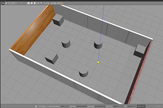
2.自定义仿真环境

2.1 启动 gazebo 打开构建面板,绘制仿真环境


2.2 保存构建的环境
点击: 左上角 file —> Save (保存路径功能包下的: models)
然后 file —> Exit Building Editor
2.3 保存为 world 文件
可以像方式1一样再添加一些插件,然后保存为 world 文件(保存路径功能包下的: worlds)

2.4 启动
同方式1
3.使用官方提供的插件
当前 Gazebo 提供的仿真道具有限,还可以下载官方支持,可以提供更为丰富的仿真实现,具体实现如下:
3.1 下载官方模型库
git clone https://github.com/osrf/gazebo_models
之前是:hg clone https://bitbucket.org/osrf/gazebo_models但是已经不可用
注意: 此过程可能比较耗时
3.2 将模型库复制进 gazebo
将得到的gazebo_models文件夹内容复制到 /usr/share/gazebo-*/models
3.3 应用
重启 Gazebo,选择左侧菜单栏的 insert 可以选择并插入相关道具了
2. URDF、Gazebo、Rviz综合应用
关于URDF(Xacro)、Rviz 和 Gazebo 三者的关系,前面已有阐述: URDF 用于创建机器人模型、Rviz 可以显示机器人感知到的环境信息,Gazebo 用于仿真,可以模拟外界环境,以及机器人的一些传感器,如何在 Gazebo 中运行这些传感器,并显示这些传感器的数据(机器人的视角)呢?本节主要介绍的重点就是将三者结合:通过 Gazebo 模拟机器人的传感器,然后在 Rviz 中显示这些传感器感知到的数据。主要内容包括:
- 运动控制以及里程计信息显示
- 雷达信息仿真以及显示
- 摄像头信息仿真以及显示
- kinect 信息仿真以及显示
2.1 机器人运动控制及里程计信息显示
gazebo 中已经可以正常显示机器人模型了,那么如何像在 rviz 中一样控制机器人运动呢?在此,需要涉及到ros中的组件: ros_control。
1.ros_control 简介
**场景:**同一套 ROS 程序,如何部署在不同的机器人系统上,比如:开发阶段为了提高效率是在仿真平台上测试的,部署时又有不同的实体机器人平台,不同平台的实现是有差异的,如何保证 ROS 程序的可移植性?ROS 内置的解决方式是 ros_control。
**ros_control:**是一组软件包,它包含了控制器接口,控制器管理器,传输和硬件接口。ros_control 是一套机器人控制的中间件,是一套规范,不同的机器人平台只要按照这套规范实现,那么就可以保证 与ROS 程序兼容,通过这套规范,实现了一种可插拔的架构设计,大大提高了程序设计的效率与灵活性。
gazebo 已经实现了 ros_control 的相关接口,如果需要在 gazebo 中控制机器人运动,直接调用相关接口即可
2.运动控制实现流程(Gazebo)
承上,运动控制基本流程:
- 已经创建完毕的机器人模型,编写一个单独的 xacro 文件,为机器人模型添加传动装置以及控制器
- 将此文件集成进xacro文件
- 启动 Gazebo 并发布 /cmd_vel 消息控制机器人运动
2.1 为 joint 添加传动装置以及控制器
两轮差速配置
<robot name="my_car_move" xmlns:xacro="http://wiki.ros.org/xacro">


    <xacro:macro name="joint_trans" params="joint_name">

        <transmission name="${joint_name}_trans">
            <type>transmission_interface/SimpleTransmissiontype>
            <joint name="${joint_name}">
                <hardwareInterface>hardware_interface/VelocityJointInterfacehardwareInterface>
            joint>
            <actuator name="${joint_name}_motor">
                <hardwareInterface>hardware_interface/VelocityJointInterfacehardwareInterface>
                <mechanicalReduction>1mechanicalReduction>
            actuator>
        transmission>
    xacro:macro>


    <xacro:joint_trans joint_name="left_wheel2base_link" />
    <xacro:joint_trans joint_name="right_wheel2base_link" />


    <gazebo>
        <plugin name="differential_drive_controller" filename="libgazebo_ros_diff_drive.so">
            <rosDebugLevel>DebugrosDebugLevel>
            <publishWheelTF>truepublishWheelTF>
            <robotNamespace>/robotNamespace>
            <publishTf>1publishTf>
            <publishWheelJointState>truepublishWheelJointState>
            <alwaysOn>truealwaysOn>
            <updateRate>100.0updateRate>
            <legacyMode>truelegacyMode>
            <leftJoint>left_wheel2base_linkleftJoint>
            <rightJoint>right_wheel2base_linkrightJoint>
            <wheelSeparation>${base_link_radius * 2}wheelSeparation>
            <wheelDiameter>${wheel_radius * 2}wheelDiameter>
            <broadcastTF>1broadcastTF>
            <wheelTorque>30wheelTorque>
            <wheelAcceleration>1.8wheelAcceleration>
            <commandTopic>cmd_velcommandTopic>
            <odometryFrame>odomodometryFrame>
            <odometryTopic>odomodometryTopic>
            <robotBaseFrame>base_footprintrobotBaseFrame>
        plugin>
    gazebo>

robot>
2.2 xacro文件集成
最后还需要将上述 xacro 文件集成进总的机器人模型文件,代码示例如下:
<robot name="my_car_camera" xmlns:xacro="http://wiki.ros.org/xacro">
    <xacro:include filename="my_head.urdf.xacro" />
    <xacro:include filename="my_base.urdf.xacro" />
    <xacro:include filename="my_camera.urdf.xacro" />
    <xacro:include filename="my_laser.urdf.xacro" />
    <xacro:include filename="move.urdf.xacro" />
robot>
当前核心: 包含 控制器以及传动配置的 xacro 文件
<xacro:include filename="move.urdf.xacro" />
2.3 启动 gazebo并控制机器人运动
launch文件:
<launch>


    <param name="robot_description" command="$(find xacro)/xacro $(find demo02_urdf_gazebo)/urdf/xacro/my_base_camera_laser.urdf.xacro" />

    <include file="$(find gazebo_ros)/launch/empty_world.launch">
        <arg name="world_name" value="$(find demo02_urdf_gazebo)/worlds/hello.world" />
    include>


    <node pkg="gazebo_ros" type="spawn_model" name="model" args="-urdf -model mycar -param robot_description"  />
launch>
启动 launch 文件,使用 topic list 查看话题列表,会发现多了 /cmd_vel 然后发布 vmd_vel 消息控制即可
使用命令控制(或者可以编写单独的节点控制)
rostopic pub -r 10 /cmd_vel geometry_msgs/Twist '{linear: {x: 0.2, y: 0, z: 0}, angular: {x: 0, y: 0, z: 0.5}}'
接下来我们会发现: 小车在 Gazebo 中已经正常运行起来了

3.Rviz查看里程计信息
在 Gazebo 的仿真环境中,机器人的里程计信息以及运动朝向等信息是无法获取的,可以通过 Rviz 显示机器人的里程计信息以及运动朝向
里程计: 机器人相对出发点坐标系的位姿状态(X 坐标 Y 坐标 Z坐标以及朝向)。
3.1启动 Rviz
launch 文件
<launch>

    <node pkg="rviz" type="rviz" name="rviz" />


    <node name="joint_state_publisher" pkg="joint_state_publisher" type="joint_state_publisher" />
    <node name="robot_state_publisher" pkg="robot_state_publisher" type="robot_state_publisher" />

launch>
3.2 添加组件
执行 launch 文件后,在 Rviz 中添加图示组件:
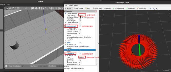
示例结果:

2.2 雷达信息仿真及显示
通过 Gazebo 模拟激光雷达传感器,并在 Rviz 中显示激光数据。
实现流程:
雷达仿真基本流程:
- 已经创建完毕的机器人模型,编写一个单独的 xacro 文件,为机器人模型添加雷达配置;
- 将此文件集成进xacro文件;
- 启动 Gazebo,使用 Rviz 显示雷达信息。
1.Gazebo 仿真雷达
1.1 新建 Xacro 文件,配置雷达传感器信息
<robot name="my_sensors" xmlns:xacro="http://wiki.ros.org/xacro">


  <gazebo reference="laser">
    <sensor type="ray" name="rplidar">
      <pose>0 0 0 0 0 0pose>
      <visualize>truevisualize>
      <update_rate>5.5update_rate>
      <ray>
        <scan>
          <horizontal>
            <samples>360samples>
            <resolution>1resolution>
            <min_angle>-3min_angle>
            <max_angle>3max_angle>
          horizontal>
        scan>
        <range>
          <min>0.10min>
          <max>30.0max>
          <resolution>0.01resolution>
        range>
        <noise>
          <type>gaussiantype>
          <mean>0.0mean>
          <stddev>0.01stddev>
        noise>
      ray>
      <plugin name="gazebo_rplidar" filename="libgazebo_ros_laser.so">
        <topicName>/scantopicName>
        <frameName>laserframeName>
      plugin>
    sensor>
  gazebo>

robot>
1.2 xacro 文件集成
将步骤1的 Xacro 文件集成进总的机器人模型文件,代码示例如下:
<robot name="my_car_camera" xmlns:xacro="http://wiki.ros.org/xacro">
    <xacro:include filename="my_head.urdf.xacro" />
    <xacro:include filename="my_base.urdf.xacro" />
    <xacro:include filename="my_camera.urdf.xacro" />
    <xacro:include filename="my_laser.urdf.xacro" />
    <xacro:include filename="move.urdf.xacro" />

    <xacro:include filename="my_sensors_laser.urdf.xacro" />
robot>
1.3启动仿真环境
编写launch文件,启动gazebo,此处略…
2.Rviz 显示雷达数据
先启动 rviz,添加雷达信息显示插件

示例结果:

2.3 摄像头信息仿真及显示
通过 Gazebo 模拟摄像头传感器,并在 Rviz 中显示摄像头数据。
实现流程:
摄像头仿真基本流程:
- 已经创建完毕的机器人模型,编写一个单独的 xacro 文件,为机器人模型添加摄像头配置;
- 将此文件集成进xacro文件;
- 启动 Gazebo,使用 Rviz 显示摄像头信息。
1.Gazebo 仿真摄像头
1.1 新建 Xacro 文件,配置摄像头传感器信息
<robot name="my_sensors" xmlns:xacro="http://wiki.ros.org/xacro">

  <gazebo reference="camera">

    <sensor type="camera" name="camera_node">
      <update_rate>30.0update_rate>

      <camera name="head">
        <horizontal_fov>1.3962634horizontal_fov>
        <image>
          <width>1280width>
          <height>720height>
          <format>R8G8B8format>
        image>
        <clip>
          <near>0.02near>
          <far>300far>
        clip>
        <noise>
          <type>gaussiantype>
          <mean>0.0mean>
          <stddev>0.007stddev>
        noise>
      camera>

      <plugin name="gazebo_camera" filename="libgazebo_ros_camera.so">
        <alwaysOn>truealwaysOn>
        <updateRate>0.0updateRate>
        <cameraName>/cameracameraName>
        <imageTopicName>image_rawimageTopicName>
        <cameraInfoTopicName>camera_infocameraInfoTopicName>
        <frameName>cameraframeName>
        <hackBaseline>0.07hackBaseline>
        <distortionK1>0.0distortionK1>
        <distortionK2>0.0distortionK2>
        <distortionK3>0.0distortionK3>
        <distortionT1>0.0distortionT1>
        <distortionT2>0.0distortionT2>
      plugin>
    sensor>
  gazebo>
robot>
1.2 xacro 文件集成
将步骤1的 Xacro 文件集成进总的机器人模型文件,代码示例如下:
<robot name="my_car_camera" xmlns:xacro="http://wiki.ros.org/xacro">
    <xacro:include filename="my_head.urdf.xacro" />
    <xacro:include filename="my_base.urdf.xacro" />
    <xacro:include filename="my_camera.urdf.xacro" />
    <xacro:include filename="my_laser.urdf.xacro" />
    <xacro:include filename="move.urdf.xacro" />

    <xacro:include filename="my_sensors_camara.urdf.xacro" />
robot>
1.3启动仿真环境
编写launch文件,启动gazebo,此处略…
2.Rviz 显示摄像头数据
执行 gazebo 并启动 Rviz,在 Rviz 中添加摄像头组件。
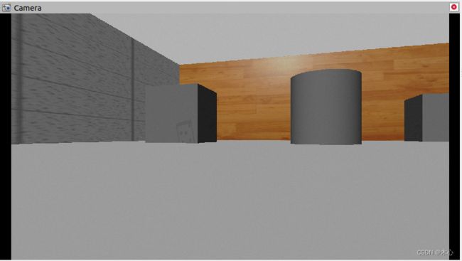

示例效果:
2.4 kinect信息仿真及显示
通过 Gazebo 模拟kinect摄像头,并在 Rviz 中显示kinect摄像头数据。
实现流程:
kinect摄像头仿真基本流程:
- 已经创建完毕的机器人模型,编写一个单独的 xacro 文件,为机器人模型添加kinect摄像头配置;
- 将此文件集成进xacro文件;
- 启动 Gazebo,使用 Rviz 显示kinect摄像头信息。
1.Gazebo仿真Kinect
1.1 新建 Xacro 文件,配置 kinetic传感器信息
<robot name="my_sensors" xmlns:xacro="http://wiki.ros.org/xacro">
    <gazebo reference="kinect link名称">
      <sensor type="depth" name="camera">
        <always_on>truealways_on>
        <update_rate>20.0update_rate>
        <camera>
          <horizontal_fov>${60.0*PI/180.0}horizontal_fov>
          <image>
            <format>R8G8B8format>
            <width>640width>
            <height>480height>
          image>
          <clip>
            <near>0.05near>
            <far>8.0far>
          clip>
        camera>
        <plugin name="kinect_camera_controller" filename="libgazebo_ros_openni_kinect.so">
          <cameraName>cameracameraName>
          <alwaysOn>truealwaysOn>
          <updateRate>10updateRate>
          <imageTopicName>rgb/image_rawimageTopicName>
          <depthImageTopicName>depth/image_rawdepthImageTopicName>
          <pointCloudTopicName>depth/pointspointCloudTopicName>
          <cameraInfoTopicName>rgb/camera_infocameraInfoTopicName>
          <depthImageCameraInfoTopicName>depth/camera_infodepthImageCameraInfoTopicName>
          <frameName>kinect link名称frameName>
          <baseline>0.1baseline>
          <distortion_k1>0.0distortion_k1>
          <distortion_k2>0.0distortion_k2>
          <distortion_k3>0.0distortion_k3>
          <distortion_t1>0.0distortion_t1>
          <distortion_t2>0.0distortion_t2>
          <pointCloudCutoff>0.4pointCloudCutoff>
        plugin>
      sensor>
    gazebo>

robot>
1.2 xacro 文件集成
将步骤1的 Xacro 文件集成进总的机器人模型文件,代码示例如下:
<robot name="my_car_camera" xmlns:xacro="http://wiki.ros.org/xacro">
    <xacro:include filename="my_head.urdf.xacro" />
    <xacro:include filename="my_base.urdf.xacro" />
    <xacro:include filename="my_camera.urdf.xacro" />
    <xacro:include filename="my_laser.urdf.xacro" />
    <xacro:include filename="move.urdf.xacro" />

    <xacro:include filename="my_sensors_kinect.urdf.xacro" />
robot>
1.3启动仿真环境
编写launch文件,启动gazebo,此处略…
2 Rviz 显示 Kinect 数据
启动 rviz,添加摄像头组件查看数据


补充:kinect 点云数据显示
在kinect中也可以以点云的方式显示感知周围环境,在 rviz 中操作如下:

问题: 在rviz中显示时错位。
原因: 在kinect中图像数据与点云数据使用了两套坐标系统,且两套坐标系统位姿并不一致。
解决:
1.在插件中为kinect设置坐标系,修改配置文件的
<frameName>support_depthframeName>
2.发布新设置的坐标系到kinect连杆的坐标变换关系,在启动rviz的launch中,添加:
<node pkg="tf2_ros" type="static_transform_publisher" name="static_transform_publisher" args="0 0 0 -1.57 0 -1.57 /support /support_depth" />
3.启动rviz,重新显示。

示例结果:

Reference
http://www.autolabor.com.cn/book/ROSTutorials/di-2-zhang-ros-jia-gou-she-ji/23-fu-wu-tong-xin/224-fu-wu-tong-xin-zi-ding-yi-srv-diao-yong-b-python.html