用arduino开发梅树派Raspberry Pi Pico
Raspberry Pi Pico 是开发板中的现代王红(“网红”,改王红吧、发文助手说不正规),网上涉及它的内容非常多,原始材料可到RaspberryPI站点上看,从入门到精通应有尽有,完全开源,不用操心某些站点又是入会又是收费的下载点儿资料。我挑重要的说,更多的东西网上说的比我说的好,去查查就得了。

开发软件主要是MicroPython和C/C++,板上有个BOOTSEL钮,把它按住了然后插上micro-usb线,Windows 就增加虚拟串口,国内本地化的一般使用的是CH340芯片,必要时装一下它的驱动。启动后增加一个U盘,上面有两个文件,是两个大小1KB的文件,有板子的信息在里面。

可以把Micro-python的解释器固件考到这盘上,考贝完成后板子重启就找不到它到哪了,但是用爱沙尼亚大学Thonny开发的话,会发现它并在上面运行micropython程序,或许将来也会有luatos等其它脚本解释器,现在好像还没有。
下面说一下用arduino如何开发它
arduino环境下开发它是直接开发,没有什么解释器在其中了。
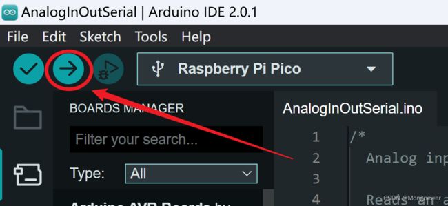
首先下载arduino 20,开源的不收费,然后默认安装即可(略)。运行arduino,然后在BOARDS MANAGER中要安装一个Arduino Mbed OS RP2040

安装好后 Mbed OS后,选串口,再选板子。

然后呢,我们测试一下ADC循环采集 AnalogOutSerial.ino , 会发现这程序与板子关系不大了,其它板子也是这么个写法儿,语言是一样的。
/*
  Analog input, analog output, serial output

  Reads an analog input pin, maps the result to a range from 0 to 255 and uses
  the result to set the pulse width modulation (PWM) of an output pin.
  Also prints the results to the Serial Monitor.

  The circuit:
  - potentiometer connected to analog pin 0.
    Center pin of the potentiometer goes to the analog pin.
    side pins of the potentiometer go to +5V and ground
  - LED connected from digital pin 9 to ground through 220 ohm resistor

  created 29 Dec. 2008
  modified 9 Apr 2012
  by Tom Igoe

  This example code is in the public domain.

  https://www.arduino.cc/en/Tutorial/BuiltInExamples/AnalogInOutSerial
*/

// These constants won't change. They're used to give names to the pins used:
const int analogInPin = A0;  // Analog input pin that the potentiometer is attached to
const int analogOutPin = 9; // Analog output pin that the LED is attached to

int sensorValue = 0;        // value read from the pot
int outputValue = 0;        // value output to the PWM (analog out)

char buff[50];

void setup() {
  // initialize serial communications at 9600 bps:
  //Serial.begin(9600);
  Serial.begin(115200);
}
void loop() {
  // read the analog in value:
  sensorValue = analogRead(analogInPin);
  // map it to the range of the analog out:
  outputValue = map(sensorValue, 0, 1023, 0, 255);
  // change the analog out value:
  analogWrite(analogOutPin, outputValue);

  // print the results to the Serial Monitor:
  //Serial.print("sensor = ");
  sprintf(buff, "sensor = %d \t\t output = %d", sensorValue, outputValue);
  Serial.println(buff);
  //Serial.print("\t\t output = ");
  //Serial.println(outputValue);

  // wait 2 milliseconds before the next loop for the analog-to-digital
  // converter to settle after the last reading:
  delay(1);
}
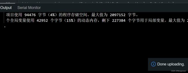
然后编译并烧录它(或叫下载)到板子上,做法是点那个右键头。
然后呢,下载成功。
有不成功的吗?有!我先是用Micropython写的循环采集,板子插到arduino下烧录不通,这些拔下USB线,按着BOOTSEL再插上,再进行烧录就成功了。
成功后,arduino的serial monitor即显示循环采集的数据

一共五个通道,最后一个是板子自己的内部测温值,其它四个在板子上由GP0-GP3引入。