实验-多路选择器
实验-多路选择器
- 实验目的
- 实验内容
- 实验设计
-
- 实验原理
- 实验过程
-
- IP核+Block Design:
-
- 与或非门的IP核封装:
- Block Design(不太美观) 以及 RTL分析:
- 行为描述方法-数据流实现方式原理(1位):
-
- 设计文件代码:
- RTL分析:
- 行为描述方法-case实现方式原理(3位):
-
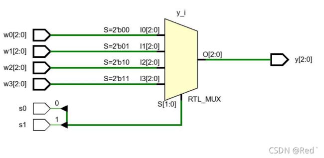
- 设计文件代码:
- 3位仿真文件代码:
- RTL分析:
- 仿真图:
实验目的
通过实验,学会多路选择器的功能,以及使用 Block Design 和 verilog
HDL 语言设计多路选择器
实验内容
1.分别使用 Block Design 设计方法和添加源代码的方法设计一个一位 4 选 1多路选择器,并通过写仿真文件、看 RTL 电路图、下载到板子验证其正确性。
2. 使用 Verilog HDL 语言的行为描述方法设计一个 3 位数据的 4 选 1 多路选择器 mux4x3。
实验设计
实验原理
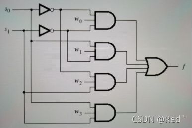
根据数据选择器,指经过选择,把多个通道的数据传到唯一的公共数据通道上。四选一数据选择器:对四个数据源进行选择,使用两位地址码A1A0产生地址信号来选择输出
4选1多路选择器真值表如下:
| 输入 | 输出 |
|---|---|
| S1 S0 | f |
| 0 0 | W0 |
| 0 1 | W1 |
| 1 0 | W2 |
| 1 1 | W3 |
逻辑表达式:f = ~S1* ~S0 * W0 + ~S1 * S0* W1 +S1* ~S0 * W2 +S1* S0* W3
实验过程
IP核+Block Design:
与或非门的IP核封装:
// 与门:
module andgate
#(parameter WIDTH=8)
(
    input [(WIDTH-1):0] a,
    input [(WIDTH-1):0] b,
    output [(WIDTH-1):0] c
    );

    assign c = a&b;
endmodule

// 或门:
module orgate
#(parameter WIDTH=8)
(
    input [(WIDTH-1):0] a,
    input [(WIDTH-1):0] b,
    output [(WIDTH-1):0] c
    );

    assign c = a|b;
endmodule

// 非门:
module notgate
#(parameter WIDTH=8)
(
    input [(WIDTH-1):0] a,
    output [(WIDTH-1):0] c
    );

    assign c = ~a;
endmodule
Block Design(不太美观) 以及 RTL分析:
行为描述方法-数据流实现方式原理(1位):
设计文件代码:
module mux4x1_ip(
    input w0,
    input w1,
    input w2,
    input w3,
    input s0,
    input s1,
    output y
);
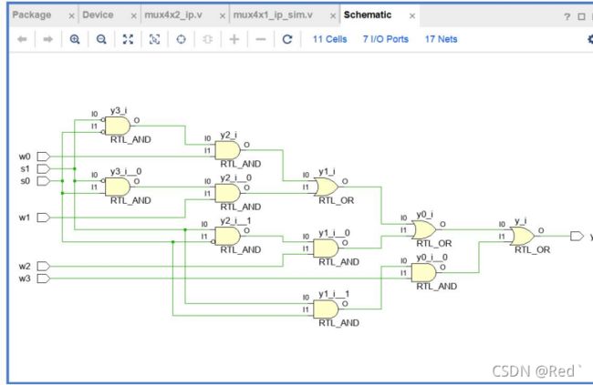
assign y = (~s1&~s0&w0)|(~s1&s0&w1)|(s1&~s0&w2)|(s1&s0&w3);
endmodule
RTL分析:
行为描述方法-case实现方式原理(3位):
设计文件代码:
module mux41(y,w0,w1,w2,w3,s0,s1);
  output reg[2:0] y;
  input[2:0] w0,w1,w2,w3;
  input s0,s1;

always @ (s0 or s1 or w0 or w1 or w2 or w3)
begin
case({s1,s0})         //  判断选择输出的数据
	 2’b00:y = w0;
	 2’b01:y = w1;
     2’b10:y = w2;
     2’b11:y = w3;
     default:y =1'bx;
 endcase
end
endmodule
3位仿真文件代码:
module mux41_sim();
reg[2:0] w0,w1,w2,w3;
reg s0,s1;
wire[2:0] y;
mux41 test(.w0(w0),.w1(w1),.w2(w2),.w3(w3),.s0(s0),.s1(s1),.y(y));
initial begin
#200
w0=001;
w1=010;
w2=100;
w3=101;
s0=0;
s1=0;
#200
w0=001;
w1=010;
w2=100;
w3=101;
s0=0;
s1=1;
#200
w0=001;
w1=010;
w2=100;
w3=101;
s0=1;
s1=0;
#200
w0=001;
w1=010;
w2=100;
w3=101;
s0=1;
s1=1;
end
endmodule
RTL分析:
仿真图:
最后上板观察就可以啦~~


