05-SA8155 QNX通过QUB配置GPIO/INT/SPI/I2C/SPI等
1. 概述
1.1 概念
GENI 通用接口 (Generic interface)
GSI 通用软件接口 (Generic software interface)
QUP 高通通用外设 (Qualcomm universal peripheral)
SE 串行引擎 (Serial engine)
TZ TrustZone
1.2 QUB v3
QUP v3 是一种可编程模块,支持多种串行接口,例如 UART、SPI、I 2 C 和 I 3 C。该模块 支持访问系统中的多个硬件实体。每个硬件实体具备专属执行环境 (EE),独立的地址空 间以及一条中断线。 通过使用内部串行引擎 (SE)/QUP,单一 QUP v3 模块可提供多达八个串行接口。每个接 口可支持的协议由加载到 SE 的固件决定。为此,可通过修改 TZ 中的 QUPAC_Access 文件加载所需协议(I 2 C、SPI 或 UART)。
QUP v3 的主要属性如下:
- 用于串行协议的单核心
- 取代了 BAM 低速外设 (BLSP) 传统核心
- 可编程的核心
1.3 GPIO
每个GPIO引脚标准具有以下功能:
- 输出
- 输入
- 中断输入(不包括特殊唤醒中断功能)
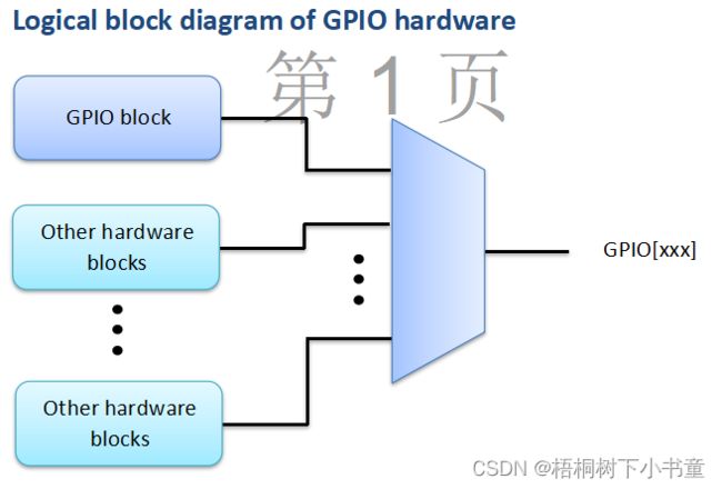
此外,一些gpio后面可能有一个或多个多路复用的硬件块,以实现其他功能。
2. SA8155 QUP配置
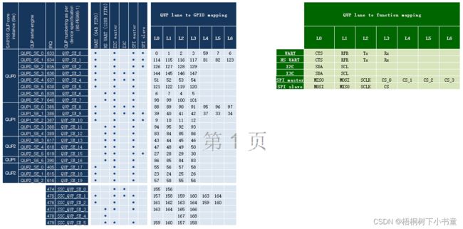
2.1 QUP-GPIO Maping映射表
QUP-GPIO Maping
如上图,QUP-GPIO映射表,代码中的配置相关均可以在这个表里查阅。
2.2 QUP资源配置:QUPAC_Access
对于SA8155的QUP访问表是:
tz_8155\trustzone_images\core\settings\buses\qup_accesscontrol\qupv3\config\855\QUPAC_Access.c
如上图所示,QUP资源配置。
2.2.1 案例,I2C资源配置
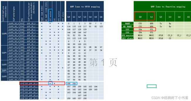
将QUPV3_SSC_SE0配置为I2C接口,拥有者为AC_HLOS
{ QUPV3_SSC_SE0, QUPV3_PROTOCOL_I2C, QUPV3_MODE_FIFO, AC_HLOS, TRUE, TRUE, FALSE }, // I2C - AUDIO A2B I2C
通过查表:
其他接口资源配置可以参考类似操作。
2.2.2 QUP功能映射关系
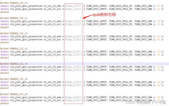
拿QUB I2C功能映射举例说明:
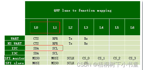
如上code,qup_l0 与 qub_l1 就是对应的 QUP lane to Function mapping功能表的L0 与 L1
图: QUP lane to Function mapping
qup_l0[x] qup_l1[x] 数组数值对应的就是QUP numbering as per device specification
qup_l0[0] qup_l1[0] 对应的就是 QUP_SE_0 的L0 与 L1 IO映射的功能配置。如果配置为I2C则是SDA与SCL。如果配置为SPI-master则为MISO与MOSI。
3. HLOS QUP programming
通过QUP programming 来初始化QUB功能以及时钟。
3.1 IO配置
文件路径:
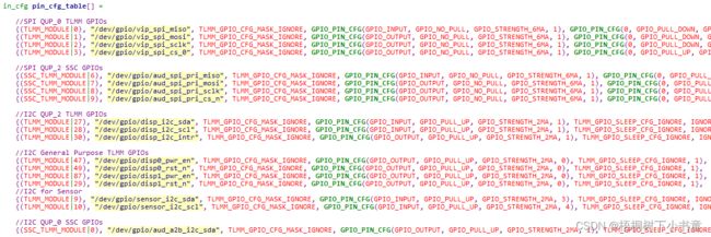
apps/qnx_ap/boards/core/dalconfig/sa8155_adp/sa8155_adp_common/config/pin_config.c
数据结构定义
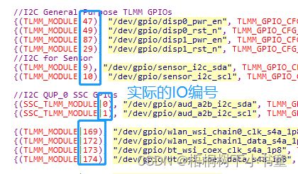
其中第一列的数值是 | 上一个IO编号。
3.2 I2C配置(例子)
3.2.1 QNX 配置文件
文件:
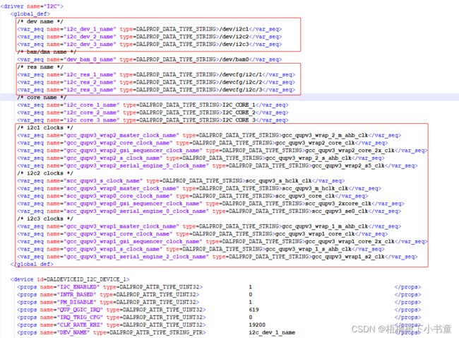
apps/qnx_ap/boards/core/dalconfig/sa8155_adp/sa8155_adp_common/config/i2c_props_8155.xml
3.2.2 I2C ID与QUP 对应
比如设置I2C1,那么这个I2C1是QUP的哪组呢? QUPV3_0_SE1? 还是QUPV3_0_SE2?
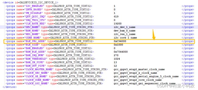
对应关系如下: 通过QUP 地址
如上图,I2C1,QUP地址为0xC94000
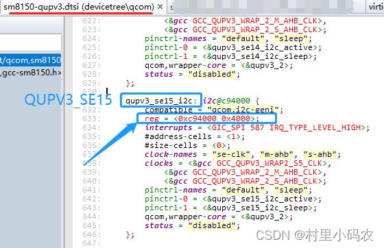
那么哪个QUBV3的地址是这个呢? 需要查手册,也可以查LA内核的设备设备树dtsi文件:如下图
3.2.3 I2C设备
i2c_props_8155.xml 配置了三个I2C:
- DALDEVICEID_I2C_DEVICE_1
- DALDEVICEID_I2C_DEVICE_2
- DALDEVICEID_I2C_DEVICE_3
且三个I2C I2C_ENABLED都是1,说明使能。
那么QNX应该会产生三个I2C设备 /dev/下:
3.2.4 I2C 调试
Linux I2C调试工具有i2c-tools 四件套(i2cset,i2cget,i2cdetect,i2cdump)。
那么QNX同样也有调试工具,它就是i2cdbgr (/bin/i2cdbgr)
usage:
# use i2cdbgr
i2cdbgr : Application to perform i2c read / write

Usage: i2cdbgr [node] [slave addr] read [byte size] [offset] [# bytes to read]
       i2cdbgr [node] [slave addr] write [byte size] [offset] [value]

where
    [node] is of form "/dev/i2cX".
    [byte size] is 1, or 2. The value has no effect for read. For write, if the
        byte size is 1, then the offset is ignored, and only [value] is written.
        If the byte size if 2, then i2cdbgr will write [offset value].

The i2cdbgr uses 8-bit addressing, 8-bit data to read or write from
    /dev/i2cX (fd) using i2c_client.h using default frequency.

Examples:
    For read:
        i2cdbgr /dev/i2c1 0x77 read 1 0x4 1 <- read 1 byte from slave addr 0x77
            offset 0x4
        i2cdbgr /dev/i2c1 0x77 read 1 0x4 5 <- read 5 bytes from slave addr
            0x77 offset 0x4

    For write:
        i2cdbgr /dev/i2c1 0x77 write 1 0x0 0xa <- write 1 byte to slave addr
            0x77 with no offset due to 1 byte size value 0xa
        i2cdbgr /dev/i2c1 0x77 write 2 0x1 0xb <- write 2 bytes to slave addr
            0x77 with offset + value bytes [0x1 0xb]
4.QNX IO调试
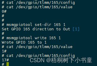
/dev/gpio
4.1 TLMM MSM GPIO tool
工具指令原型:
$msmgpiotool
| Command | gpio | arg | 描述 |
| info | 无 | Display the info for the specified TLMM GPIO | |
| write | Write the GPIO pin value | ||
| read | 无 | Read the GPIO pin value (High or Low) | |
| rawread | 无 | Read the GPIO IN_OUT register raw register value | |
| set-dir | Set the GPIO direction | ||
| set-drive | Set the GPIO drive strength | ||
| set-pull | Set the GPIO drive mode | ||
| set-func | Set the GPIO function select | ||
| enable-irq | Set the GPIO interrupt source | ||
| clear-irq | 无 | Clears the pending irq status | |
| set-pol | Sets the GPIO interrupt polarity | ||
| set-trigger | Sets the irq trigger type |
QNX 使用方法:
$ msmgpiotool read 8
GPIO 8 is Low
$ msmgpiotool set-dir 8 1
Set GPIO 8 direction to Out [1]
$ msmgpiotool write 8 1
Wrote GPIO 8 to 1
$ msmgpiotool read 8
GPIO 8 is High
4.2 PMIC GPIO tool
工具指令原型
$ pmicgpiotool
Tool 命令,与TLMM MSM GPIO tool类似
read
gpio-master
source-select
mode-inversion
voltage-select
pullup-select
output-type
output-drive-select
mode
in-set-type
int-polarity-high
int-polarity-low
int-enable-set
int-enable-clear
int-mid-select
int-priority
