输入系统应用编程
1. 什么是输入系统
先来了解什么是输入设备?
常见的输入设备有键盘、鼠标、遥控杆、书写板、触摸屏等等, 用户通过这些输入设备与 Linux 系统进行数据交换。
什么是输入系统?
输入设备种类繁多,能否统一它们的接口?既在驱动层面统一,也在应用程序层面统一?可以的。
Linux 系统为了统一管理这些输入设备,实现了一套能兼容所有输入设备的框架:输入系统。驱动开发人员基于这套框架开发出程序,应用开发人员就可以使用统一的 API 去使用设备。
2 输入系统框架及调试
2.1 框架概述
作为应用开发人员,可以只基于 API 使用输入子系统。但是了解内核中输入子系统的框架、了解数据流程,有助于解决开发过程中碰到的硬件问题、驱动问题。
输入系统框架如图 所示:

假设用户程序直接访问/dev/input/event0 设备节点,或者使用 tslib 访问设备节点,数据的流程如下:
1.APP 发起读操作,若无数据则休眠;
2.用户操作设备,硬件上产生中断;
3.输入系统驱动层对应的驱动程序处理中断:读取到数据,转换为标准的输入事件,向核心层汇报。 所谓输入事件就是一个“struct input_event ”结构体。
4.核心层可以决定把输入事件转发给上面哪个 handler 来处理:
从 handler 的名字来看,它就是用来处输入操作的。有多种 handler ,比如:evdev_handler 、kbd_handler、 joydev_handler 等等。
最常用的是 evdev_handler :它只是把 input_event 结构体保存在内核 buffer 等, APP 来读取时就原原本本地返回。它支持多个 APP 同时访问输入设备,每个 APP 都可以获得同一份输入事件。
当 APP 正在等待数据时, evdev_handler 会把它唤醒,这样 APP 就可以返回数据。
5.APP 对输入事件的处理:
APP 获 得 数 据 的 方 法 有 2 种 : 直 接 访 问 设 备 节 点 ( 比 如/dev/input/event0,1,2,...),或者通过 tslib 、 libinput 这类库来间接访问设备节点。这些库简化了对数据的处理。
2.2 编写 APP 需要掌握的知识
2.2.1 内核中怎么表示一个输入设备?
使用 input_dev 结构体来表示输入设备,它的内容如图输入设备结构体:

2.2.2 APP 可以得到什么数据?
可以得到一系列的输入事件,就是一个一个“struct input_event ”,它定义如图输入事件结构体:

每个输入事件 input_event 中都含有发生时间: timeval 表示的是“自系统启动以来过了多少时间”,它是一个结构体,含有“tv_sec 、 tv_usec ”两项 (即秒、微秒 ) 。
输入事件 input_event 中更重要的是: type( 哪类事件 ) 、 code( 哪个事件 ) 、value(事件值 ) ,细讲如下:
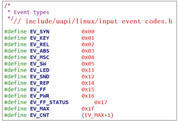
1.type :表示哪类事件
比如 EV_KEY 表示按键类、 EV_REL 表示相对位移 ( 比如鼠标 ) , EV_ABS 表示绝对位置( 比如触摸屏 ) 。如下图 这几类事件 ( 参考 Linux 内核头文件 ) :
2. code: 表示该类事件下的哪一个事件
比如对于 EV_KEY( 按键 ) 类事件,它表示键盘。键盘上有很多按键,比如数字键 1 、 2 、 3 ,字母键 A 、 B 、 C 里等。所以可以有下图 这些事件:

对于触摸屏,它提供的是绝对位置信息,有 X 方向、 Y 方向,还有压力值。所以 code 值有下图 这些:

3. value :表示事件值
对于按键,它的 value 可以是 0( 表示按键被按下 ) 、 1( 表示按键被松开 ) 、2(表示长按 ) ;
对于触摸屏,它的 value 就是坐标值、压力值。
4.事件之间的界线
APP 读取数据时,可以得到一个或多个数据,比如一个触摸屏的一个触点会上报 X 、 Y 位置信息,也可能会上报压力值。
◼ APP 怎么知道它已经读到了完整的数据?
驱动程序上报完一系列的数据后,会上报一个“同步事件”,表示数据上报完毕。APP 读到“同步事件”时,就知道已经读完了当前的数据。
同步事件也是一个 input_event 结构体,它的 type 、 code 、 value 三项都是 0 。
2.2.3 输入子系统支持完整的 API 操作
支持这些机制:阻塞、非阻塞、 POLL/SELECT 、异步通知。
2.3 调试技巧
2.3.1 确定设备信息
输入设备的设备节点名为/dev/input/eventX( 也可能是 /dev/eventX , X表示 0 、 1 、 2 等数字 ) 。查看设备节点,可以执行以下命令:
ls /dev/input/* -l 或
ls /dev/event* -l可以看到图类似下面的信息:

怎么知道这些设备节点对应什么硬件呢?可以在板子上执行以下命令:
cat /proc/bus/input/devices 这条指令的含义就是获取与 event 对应的相关设备信息,可以看到类似以下的结果:
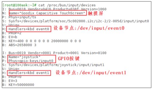
那么这里的 I 、 N 、 P 、 S 、 U 、 H 、 B 对应的每一行是什么含义呢?
1. I:id of the device( 设备 ID)
该参数由结构体 struct input_id 来进行描述,驱动程序中会定义这样的结构体:

2. N:name of the device 设备名称
3. P:physical path to the device in the system hierarchy
系统层次结构中设备的物理路径。
4. S:sysfs path 位于 sys 文件系统的路径
5. U:unique identification code for the device(if device has it) 设备的唯一标识码
6. H:list of input handles associated with the device.与设备关联的输入句柄列表。
7. B:bitmaps( 位图 )
PROP:device properties and quirks(设备属性)
EV:types of events supported by the device(设备支持的事件类型)
KEY:keys/buttons this device has(此设备具有的键/按钮)
MSC:miscellaneous events supported by the device(设备支持的其他事件)
LED:leds present on the device(设备上的指示灯)
值得注意的是 B 位图,比如上图中“ B: EV=b ”用来表示该设备支持哪类输入事件。b 的二进制是 1011 , bit0 、 1 、 3 为 1 ,表示该设备支持 0 、 1 、 3 这三类事件,即 EV_SYN 、 EV_KEY 、 EV_ABS 。
再举一个例子,“ B: ABS=2658000 3 ”如何理解?
它表示该设备支持 EV_ABS 这一类事件中的哪一些事件。这是 2 个 32 位的数字:0x2658000 、 0x3 ,高位在前低位在后,组成一个 64 位的数字:“0x2658000,00000003” ,数值为 1 的位有: 0 、 1 、 47 、 48 、 50 、 53 、 54 ,即:0、 1 、 0x2f 、 0x30 、 0x32 、 0x35 、 0x36 ,对应以下这些宏:

2.3.2 使用命令读取数据
调试输入系统时,直接执行类似下面的命令,然后操作对应的输入设备即可读出数据:
hexdump /dev/input/event0 在开发板上执行上述命令之后,点击按键或是点击触摸屏,就会打印如图信息:

上图中 的 type 为 3 ,对应 EV_ABS ; code 为 0x35 对 应ABS_MT_POSITION_X; code 为 0x36 对应 ABS_MT_POSITION_Y 。
上图中还发现有 2 个同步事件:它的 type、code、 value 都为 0 。表示电容屏上报了 2 次完整的数据。
3 不使用库的应用程序示例
3.1 APP 访问硬件的 4 种方式:妈妈怎么知道孩子醒了

妈妈怎么知道卧室里小孩醒了?
1. 时不时进房间看一下: 查询方式
简单,但是累
2.进去房间陪小孩一起睡觉,小孩醒了会吵醒她: 休眠 - 唤醒
不累,但是妈妈干不了活了
3.妈妈要干很多活,但是可以陪小孩睡一会,定个闹钟: poll 方式
要浪费点时间,但是可以继续干活。
妈妈要么是被小孩吵醒,要么是被闹钟吵醒。
4. 妈妈在客厅干活,小孩醒了他会自己走出房门告诉妈妈: 异步通知
妈妈、小孩互不耽误。
这 4 种方法没有优劣之分,在不同的场合使用不同的方法。
3.2 获取设备信息
通过 ioctl 获取设备信息, ioctl 的参数如下:
int ioctl(int fd, unsigned long request, ...);有些驱动程序对 request 的格式有要求,它的格式如下:

比如 dir 为 _IOC_READ( 即 2) 时,表示 APP 要读数据;为 _IOC_WRITE( 即 4)时,表示 APP 要写数据。
⚫ size 表示这个 ioctl 能传输数据的最大字节数。
⚫ type 、 nr 的含义由具体的驱动程序决定。
比如要读取输入设备的 evbit 时, ioctl 的 request 要写为“ EVIOCGBIT(0, size)”, size 的大小可以由你决定:你想读多少字节就设置为多少。这个宏的定义如下:
3.3 查询方式
APP 调用 open 函数时,传入“ O_NONBLOCK ”表示“非阻塞”。
APP 调用 read 函数读取数据时,如果驱动程序中有数据,那么 APP 的 read 函数会返回数据,否则也会立刻返回错误。
3.4 休眠-唤醒方式
APP 调用 open 函数时,不要传入“ O_NONBLOCK ”。
APP 调用 read 函数读取数据时,如果驱动程序中有数据,那么 APP 的 read 函数会返回数据;否则 APP 就会在内核态休眠,当有数据时驱动程序会把 APP 唤醒,read 函数恢复执行并返回数据给 APP 。
3.5 POLL/SELECT 方式
3.5.1 功能介绍
POLL 机制、 SELECT 机制是完全一样的,只是 APP 接口函数不一样。
简单地说,它们就是“定个闹钟”:在调用 poll 、 select 函数时可以传入 “超时时间”。在这段时间内,条件合适时( 比如有数据可读、有空间可写 ) 就会立刻返回,否则等到“超时时间”结束时返回错误。
用法如下。
⚫ APP 先调用 open 函数时。
⚫ APP 不是直接调用 read 函数,而是先调用 poll 或 select 函数,这 2 个函数中可以传入“超时时间”。它们的作用是:如果驱动程序中有数据,则立刻返回;否则就休眠。在休眠期间,如果有人操作了硬件,驱动程序获得数据后就会把 APP唤醒,导致 poll 或 select 立刻返回;如果在“超时时间”内无人操作硬件,则时间到后 poll 或 select 函数也会返回。 APP 可以根据函数的返回值判断返回原因:有数据?无数据超时返回?
⚫ APP 根据 poll 或 select 的返回值判断有数据之后,就调用 read 函数读取数据时,这时就会立刻获得数据。
⚫ poll/select 函数可以监测多个文件,可以监测多种事件:

在调用 poll 函数时,要指明:
⚫ 你要监测哪一个文件:哪一个 fd
⚫ 你想监测这个文件的哪种事件:是 POLLIN 、还是 POLLOUT
最后,在 poll 函数返回时,要判断状态。
应用程序代码如下:
struct pollfd fds[1];
int timeout_ms = 5000;
int ret;
fds[0].fd = fd;
fds[0].events = POLLIN;
ret = poll(fds, 1, timeout_ms);
if ((ret == 1) && (fds[0].revents & POLLIN))
{
    read(fd, &val, 4);
    printf("get button : 0x%x\n", val);
}
3.5.2 现在编程:使用 POLL
核心源码如下:
#include
#include
#include
#include
#include
#include
#include
#include
#include


/* ./01_get_input_info /dev/input/event0 */
int main(int argc, char **argv)
{
	int fd;
	int err;
	int len;
	int ret;
	int i;
	unsigned char byte;
	int bit;
	struct input_id id;
	unsigned int evbit[2];
	struct input_event event;
	struct pollfd fds[1];
	nfds_t nfds = 1;

	char *ev_names[] = {
		"EV_SYN ",
		"EV_KEY ",
		"EV_REL ",
		"EV_ABS ",
		"EV_MSC ",
		"EV_SW	",
		"NULL ",
		"NULL ",
		"NULL ",
		"NULL ",
		"NULL ",
		"NULL ",
		"NULL ",
		"NULL ",
		"NULL ",
		"NULL ",
		"NULL ",
		"EV_LED ",
		"EV_SND ",
		"NULL ",
		"EV_REP ",
		"EV_FF	",
		"EV_PWR ",
		};

	if (argc != 2)
	{
		printf("Usage: %s \n", argv[0]);
		return -1;
	}

	fd = open(argv[1], O_RDWR | O_NONBLOCK);//打开设备文件。
	if (fd < 0)
	{
		printf("open %s err\n", argv[1]);
		return -1;
	}

	err = ioctl(fd, EVIOCGID, &id);
	if (err == 0)
	{
		printf("bustype = 0x%x\n", id.bustype );
		printf("vendor	= 0x%x\n", id.vendor  );
		printf("product = 0x%x\n", id.product );
		printf("version = 0x%x\n", id.version );
	}

	len = ioctl(fd, EVIOCGBIT(0, sizeof(evbit)), &evbit);
	if (len > 0 && len <= sizeof(evbit))
	{
		printf("support ev type: ");
		for (i = 0; i < len; i++)
		{
			byte = ((unsigned char *)evbit)[i];
			for (bit = 0; bit < 8; bit++)
			{
				if (byte & (1< 0)
		{
			if (fds[0].revents == POLLIN)
			{
				while (read(fd, &event, sizeof(event)) == sizeof(event))
				{
					printf("get event: type = 0x%x, code = 0x%x, value = 0x%x\n", event.type, event.code, event.value);
				}
			}
		}
		else if (ret == 0)//判断返回值:大于 0 表示期待的事件发生了,等于 0 表示超时。
		{
			printf("time out\n");
		}
		else
		{
			printf("poll err\n");
		}
	}

	return 0;
}
3.6 异步通知方式
3.6.1 功能介绍
所谓同步,就是“你慢我等你”。
那么异步就是:你慢那你就自己玩,我做自己的事去了,有情况再通知我。
所谓异步通知,就是 APP 可以忙自己的事,当驱动程序用数据时它会主动给 APP 发信号,这会导致 APP 执行信号处理函数。
仔细想想“ 发信号 ”,这只有 3 个字,却可以引发很多问题:
⚫ 谁发:驱动程序发
⚫ 发什么:信号
⚫ 发什么信号: SIGIO
⚫ 怎么发:内核里提供有函数
⚫ 发给谁: APP , APP 要把自己告诉驱动
⚫ APP 收到后做什么:执行信号处理函数
⚫ 信号处理函数和信号,之间怎么挂钩: APP 注册信号处理函数
小孩通知妈妈的事情有很多:饿了、渴了、想找人玩。
Linux 系统中也有很多信号,在 Linux 内核源文件 include\uapi\asm-generic\signal.h 中,有很多信号的宏定义:
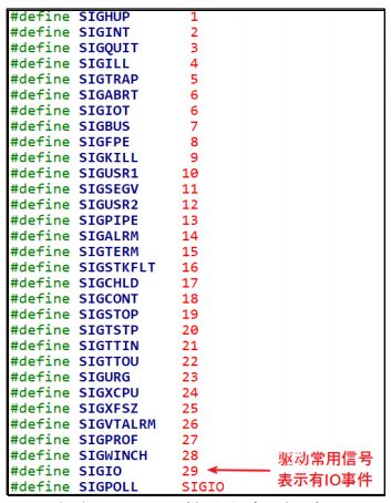
驱动程序通知 APP 时,它会发出“ SIGIO ”这个信号,表示有“ IO 事件”要处理。
就 APP 而言,你想处理 SIGIO 信息,那么需要提供信号处理函数,并且要跟 SIGIO 挂钩。这可以通过一个 signal 函数来“给某个信号注册处理函数”,用法如下:

除了注册 SIGIO 的处理函数, APP 还要做什么事?想想这几个问题:
⚫ 内核里有那么多驱动,你想让哪一个驱动给你发 SIGIO 信号?
APP 要打开驱动程序的设备节点。
⚫ 驱动程序怎么知道要发信号给你而不是别人? APP 要把自己的进程 ID 告诉驱动程序。
⚫ APP 有时候想收到信号,有时候又不想收到信号:应该可以把 APP 的意愿告诉驱动:设置 Flag 里面的 FASYNC 位为 1 ,使能“异步通知”。
3.6.2 应用编程
应用程序要做的事情有这几件:
1. 编写信号处理函数:
static void sig_func(int sig)
{
    int val;
    read(fd, &val, 4);
    printf("get button : 0x%x\n", val);
}2.注册信号处理函数:
signal(SIGIO, sig_func);3.打开驱动:
fd = open(argv[1], O_RDWR);4.把进程 ID 告诉驱动:
fcntl(fd, F_SETOWN, getpid());5.使能驱动的 FASYNC 功能:
flags = fcntl(fd, F_GETFL);
fcntl(fd, F_SETFL, flags | FASYNC);
#include
#include
#include
#include
#include
#include
#include
#include
#include
#include
#include
int fd;
void my_sig_handler(int sig)
{
struct input_event event;
while (read(fd, &event, sizeof(event)) == sizeof(event))
{
printf("get event: type = 0x%x, code = 0x%x, value = 0x%x\n", event.type, event.code, event.value);
}
}
/* ./05_input_read_fasync /dev/input/event0 */
int main(int argc, char **argv)
{
int err;
int len;
int ret;
int i;
unsigned char byte;
int bit;
struct input_id id;
unsigned int evbit[2];
unsigned int flags;
int count = 0;
char *ev_names[] = {
"EV_SYN ",
"EV_KEY ",
"EV_REL ",
"EV_ABS ",
"EV_MSC ",
"EV_SW ",
"NULL ",
"NULL ",
"NULL ",
"NULL ",
"NULL ",
"NULL ",
"NULL ",
"NULL ",
"NULL ",
"NULL ",
"NULL ",
"EV_LED ",
"EV_SND ",
"NULL ",
"EV_REP ",
"EV_FF ",
"EV_PWR ",
};
if (argc != 2)
{
printf("Usage: %s \n", argv[0]);
return -1;
}
/* 注册信号处理函数 */
signal(SIGIO, my_sig_handler);
/* 打开驱动程序 */
fd = open(argv[1], O_RDWR | O_NONBLOCK);
if (fd < 0)
{
printf("open %s err\n", argv[1]);
return -1;
}
err = ioctl(fd, EVIOCGID, &id);
if (err == 0)
{
printf("bustype = 0x%x\n", id.bustype );
printf("vendor = 0x%x\n", id.vendor );
printf("product = 0x%x\n", id.product );
printf("version = 0x%x\n", id.version );
}
len = ioctl(fd, EVIOCGBIT(0, sizeof(evbit)), &evbit);
if (len > 0 && len <= sizeof(evbit))
{
printf("support ev type: ");
for (i = 0; i < len; i++)
{
byte = ((unsigned char *)evbit)[i];
for (bit = 0; bit < 8; bit++)
{
if (byte & (1< 4 电阻屏和电容屏
触摸屏分为电阻屏、电容屏。电阻屏结构简单,在以前很流行;电容屏支持多点触摸,现在的手机基本都是使用电容屏。
注意 : LCD 、触摸屏不是一回事, LCD 是输出设备,触摸屏是输入设备。制作触摸屏时特意把它的尺寸做得跟 LCD 一模一样,并且把触摸屏覆盖在 LCD 上。
4.1 电阻屏
4.1.1复习一下欧姆定律
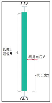
图中的电阻假设是均匀的,就是长度和阻值成正比关系。电阻长度为 L,阻值为 R ,在两端施加 3.3V 电压。在某点测得电阻为 V ,求上图中长度 X 。
根据欧姆定律:3.3/R = V/Rx ,
因为长度和阻值成正比关系,上述公式转换为: 3.3/L = V/X ,所以 X=LV/3.3 。
4.1.2电阻屏原理
电阻屏就是基于欧姆定律制作的,它有上下两层薄膜,这两层薄膜就是两个电阻,如下图所示:
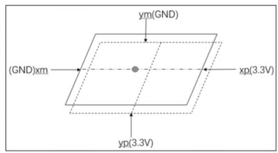
平时上下两层薄膜无触触,当点击触摸屏时,上下两层薄膜接触:这时就可以测量触点电压。过程如下:
1. 测量 X 坐标:
在 xp 、 xm 两端施加 3.3V 电压, yp 和 ym 不施加电压 (yp 就相当于探针 ) ,测量 yp 电压值。该电压值就跟 X 坐标成正比关系,假设:
X = 3.3*Vyp/Xmax
2. 测量 Y 坐标:
在 yp 、 ym 两端施加 3.3V 电压, xp 和 xm 不施加电压 (xp 就相当于探针 ) ,测量 xp 电压值。该电压值就跟 Y 坐标成正比关系,假设:
Y = 3.3*Vxp/Ymax
在实际使用时,电阻屏的 Xmax 、 Ymax 无从得知,所以使用之前要先较准:依次点击触摸屏的四个角和中心点,推算出 X 、 Y 坐标的公式:
X = func(Vyp)
Y = func(Vxp)
3. 电阻屏数据
Linux 驱动程序中,会上报触点的 X 、 Y 数据,注意:这不是 LCD 的坐标值,需要 APP 再次处理才能转换为 LCD 坐标值。
对应的 input_event 结构体中,“ type 、 code 、 value ”如下:
按下时:
EV_KEY BTN_TOUCH 1 /* 按下 */
EV_ABS ABS_PRESSURE 1 /* 压力值,可以上报,也可以不报,可以是其他压力值 */
EV_ABS ABS_X x_value /* X 坐标 */
EV_ABS ABS_Y y_value /* Y 坐标 */
EV_SYNC 0 0 /* 同步事件 */
松开时:
EV_KEY BTN_TOUCH 0 /* 松开 */
EV_ABS ABS_PRESSURE 0 /* 压力值,可以上报,也可以不报 */
EV_SYNC 0 0 /* 同步事件 */
4.2 电容屏
4.2.1 原理

电容屏中有一个控制芯片,它会周期性产生驱动信号,接收电极接收到信号,并可测量电荷大小。当电容屏被按下时,相当于引入了新的电容,从而影响了接收电极接收到的电荷大小。主控芯片根据电荷大小即可计算出触点位置。
怎么通过电荷计算出触点位置?这由控制芯片实现,这类芯片一般是 I2C 接口。
我们只需要编写程序,通过 I2C 读取芯片寄存器即可得到这些数据。
4.2.2 电容屏数据
电容屏可以支持多点触摸(Multi touch) ,驱动程序上报的数据中怎么分辨触点?
这有两种方法: Type A 、 Type B ,这也对应两种类型的触摸屏:
1. Type A
该类型的触摸屏不能分辨是哪一个触点,它只是把所有触点的坐标一股脑地上报,由软件来分辨这些数据分别属于哪一个触点。
Type A 已经过时, Linux 内核中都没有 Type A 的源码了。
2. Type B
该类型的触摸屏能分辨是哪一个触点,上报数据时会先上报触点 ID ,再上报它的数据。
具体例子如下,这是最简单的示例,使用场景分析来看看它上报的数据。
当有 2 个触点时 (type, code, value) :
EV_ABS ABS_MT_SLOT 0 // 这表示“我要上报一个触点信息了”,用来分隔触点信息
EV_ABS ABS_MT_TRACKING_ID 45 // 这个触点的 ID 是 45
EV_ABS ABS_MT_POSITION_X x[0] // 触点 X 坐标
EV_ABS ABS_MT_POSITION_Y y[0] // 触点 Y 坐标
EV_ABS ABS_MT_SLOT 1 // 这表示“我要上报一个触点信息了”,用来分隔触点信息
EV_ABS ABS_MT_TRACKING_ID 46 // 这个触点的 ID 是 46
EV_ABS ABS_MT_POSITION_X x[1] // 触点 X 坐标
EV_ABS ABS_MT_POSITION_Y y[1] // 触点 Y 坐标
EV_SYNC SYN_REPORT 0 // 全部数据上报完毕
当 ID 为 45 的触点正在移动时:
EV_ABS ABS_MT_SLOT 0 // 这表示“我要上报一个触点信息了”,之前上报过 ID,就不用再上报 ID了
EV_ABS ABS_MT_POSITION_X x[0] // 触点 X 坐标
EV_SYNC SYN_REPORT 0 // 全部数据上报完毕
松开 ID 为 45 的触点时 ( 在前面 slot 已经被设置为 0 ,这里这需要再重新设置 slot, slot 就像一个全局变量一样:如果它没变化的话,就无需再次设置 ) :
// 刚刚设置了 ABS_MT_SLOT 为 0,它对应 ID 为 45,这里设置 ID 为-1 就表示 ID 为 45 的触点被松开了
EV_ABS ABS_MT_TRACKING_ID -1
EV_SYNC SYN_REPORT 0 // 全部数据上报完毕
最后,松开 ID 为 46 的触点:
EV_ABS ABS_MT_SLOT 1 // 这表示“我要上报一个触点信息了”,在前面设置过 slot 1 的 ID为 46
EV_ABS ABS_MT_TRACKING_ID -1 // ID 为-1,表示 slot 1 被松开,即 ID 为 46 的触点被松开
EV_SYNC SYN_REPORT // 全部数据上报完毕
4.3 电容屏的实验数据
假设你的开发板上电容屏对应的设备节点是/dev/input/event0 ,执行以下命令:
hexdump /dev/input/event0
在上面的数据中,为了兼容老程序,它也上报了 ABS_X 、 ABS_Y 数据,电阻触摸屏就是使用这类型的数据。所以基于电阻屏的程序,也可以用在电容屏上。使用两个手指点击触摸屏时,得到类似如下的数据:

为了兼容老程序,它也上报了 ABS_X 、 ABS_Y 数据,但是只上报第 1 个触点的数据。
5 tslib
编译 tslib 后,可以得到 libts 库,还可以得到各种工具:较准工具、测试工具。
5.1 tslib 框架分析
tslib 的主要代码如图:
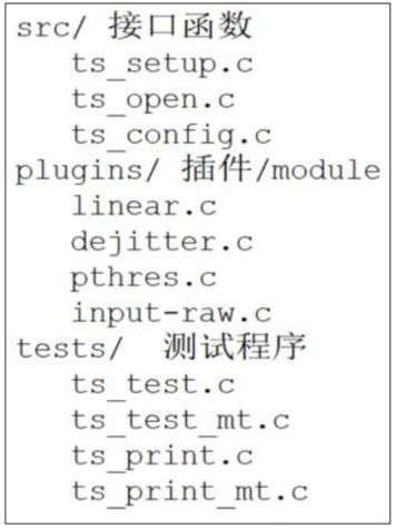
核心在于“plugins ”目录里的“插件”,或称为“ module ”。这个目录下的每个文件都是一个 module ,每个 module 都提供 2 个函数: read 、 read_mt ,前者用于读取单点触摸屏的数据,后者用于读取多点触摸屏的数据。
要分析 tslib 的框架,先看看示例程序怎么使用,我们参考 ts_test.c 和ts_test_mt.c,前者用于一般触摸屏 ( 比如电阻屏、单点电容屏 ) ,后者用于多点触摸屏。
一个图就可以弄清楚 tslib 的框架:

调用 ts_open 后,可以打开某个设备节点,构造出一个 tsdev 结构体。然后调用 ts_config 读取配置文件的处理,假设 /etc/ts.conf 内容如下:
module_raw input
module pthres pmin=1
module dejitter delta=100
module linear每行表示一个“module”或“moduel_raw”。
对于所有的“module”,都会插入 tsdev.list 链表头,也就是 tsdev.list 执行配置文件中最后一个“module”,配置文件中第一个“module”位于链表的 尾部。
对于所有的“module_raw ”,都会插入 tsdev.list_raw 链表头,一般只有一个“module_raw ”。
注意 : tsdev.list 中最后一个“ module ”会指向 ts_dev.list_raw 的头部。
无论是调用 ts_read 还是 ts_read_mt ,都是通过 tsdev.list 中的模块来处理数据的。这写模块是递归调用的,比如linear 模块的 read 函数如图

linear 模块的 read_raw 函数如图
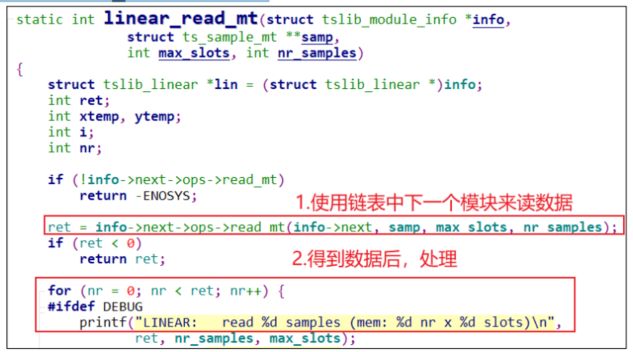
因为是递归调用,所有最先使用 input 模块读取设备节点得到原始数据,再依次经过 pthres 模块、 dejitter 模块、 linear 模块处理后,才返回最终数据。
5.2 交叉编译、测试 tslib
5.2.1 交叉编译 tslib
export ARCH=arm
export CROSS_COMPILE=arm-linux-gnueabihf-
export PATH=$PATH:/home/book/100ask_imx6ull-sdk/ToolChain/gcc-linaro-6.2.1-2016.11-x86_64_arm-linux-gnueabihf/bin
交叉编译 tslib :
./configure --host=arm-linux-gnueabihf --prefix=/
make
make install DESTDIR=$PWD/tmp
确定工具链中头文件、库文件目录:
echo 'main(){}'| arm-linux-gnueabihf-gcc -E -v - 把头文件、库文件放到工具链目录下:
cd tslib-1.21/tmp/
cp include/* /home/book/100ask_imx6ull-sdk/ToolChain/gcc-linaro-6.2.1-2016.11-x86_64_arm-linux-gnueabihf/bin/../arm-linux-gnueabihf/libc/usr/include
cp -d lib/*so* /home/book/100ask_imx6ull-sdk/ToolChain/gcc-linaro-6.2.1-2016.11-x86_64_arm-linux-gnueabihf/bin/../arm-linux-gnueabihf/libc/usr/lib/
5.2.2 测试 tslib
把库文件放到单板上:运行程序要用。先在开发板上使用 NFS 挂载 Ubuntu 的目录,再把前面编译出来的 tslib-1.21/tmp/ 部分文件复制到板子上,示例命令如下:
cp /mnt/tslib-1.21/tmp/lib/*so* -d /lib
cp /mnt/tslib-1.21/tmp/bin/* /bin
cp /mnt/tslib-1.21/tmp/etc/ts.conf -d /etc
对于 IMX6ULL ,首先需要关闭默认的 qt gui 程序,才可以执行 ts_test_mt 测试命令,关闭 qt 命令如下所示:
mv /etc/init.d/S07hmi /root
reboot
在单板上执行测试程序:
ts_test_mt5.3 自己写一个测试程序
5.3.1 接口函数深入分析

驱动程序使用 slot 、 tracking_id 来标识一个触点;当 tracking_id 等于 -1 时,标识这个触点被松开了。
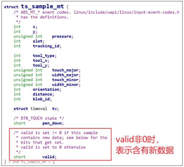
触摸屏可能支持多个触点,比如 5 个: tslib 为了简化处理,即使只有 2 个触点,ts_read_mt 函数也会返回 5 个触点数据,可以根据标志位判断数据是否
有效。
ts_read_mt 函数原型如图 :

假设nr 设置为 1 , max_slots 设置为 5 ,那么读到的数据保存在: samp[0][0] 、 samp[0][1]、 samp[0][2] 、 samp[0][3] 、 samp[0][4] 中。
假设nr 设置为 2 , max_slots 设置为 5 ,那么读到的数据保存在:samp[0][0]、 samp[0][1] 、 samp[0][2] 、 samp[0][3] 、 samp[0][4] 和 samp[1][0] 、 samp[1][1]、 samp[1][2] 、 samp[1][3] 、 samp[1][4] 中。
ts_sample_mt 结构体如图