国民技术Cortex-M0系列单片机IAP升级
考虑到设备部署到现场后有可能需要进行软件升级,之前做过PIC系列单片机的升级,现在想做个国民技术N32G031系列Cortex-M0内核的单片机IAP方案。
因为国民技术系列单片机在很多大程度上都模仿了STM32,所以我想其升级方案极有可能差不多。于是在网上下载了STM32官方使用YMODEM协议实现的IAP,下载地址:STSW-STM32008 - STM32F10xxx in-application programming using the USART (AN2557) - STMicroelectronics,使用野火的STM32开发实测过是没有问题的,于是在它的基础上进行修改,移植到N32G031系列单片机中来,经过一番折腾还是搞定了,现在把相关内容分享下,另外资源可以在以下链接中下载,无需积分。
【免费】国民技术N32G031使用YMODEM协议实现IAP资源-CSDN文库
另外,关于YMODEM协议及secureCRT的使用可以参考以下链接:
stm32 Bootloader设计(YModem协议)-CSDN博客
关于secureCRT的破解方法请参考以下链接:
尝试SecureCRT_securecrt issue date-CSDN博客
主要介绍IAP程序的main.c文件,代码如下:
/**
 * @file main.c
 * @author Power
 * @version V1.0.1
 *
 * @copyright Copyright (c) 2023, DS.
 */
/*
    MIPS的全称是Million Instructions Per Second,
    每秒百万指令(西方或者国际上的计量体系中1M(兆)=100万=1000000);Mhz,是指单片机CPU的主频兆赫兹。
    单条指令执行时间:STM32F10X单片机在主频为72MHz下,C语言程序执行一条指令需要的时间可认为10ns~100ns。
    国民技术系列N32G031 MCU,以主频48MHz为例,这里估算的C语言执行一条指令的时间约为20ns-200ns
*/

#include "main.h"
#include "common.h"
#include "ymodem.h"

#define 	COMn                2
#define     RS485_GPIOx_CLK     RCC_APB2_PERIPH_GPIOF   //peripheral adress
#define     RS485_GPIO_PIN      GPIO_PIN_6              //pin address
#define     RS485_GPIOx         GPIOF                   //port address
#define     RS485_L()           GPIO_ResetBits(RS485_GPIOx, RS485_GPIO_PIN)//RECEIVE_ mode
#define     RS485_H()           GPIO_SetBits(RS485_GPIOx, RS485_GPIO_PIN)//TRANSMIT mode

typedef enum
{
  COM1 = 0,
  COM2 = 1
} COM_TypeDef;

/* Private typedef -----------------------------------------------------------*/
/* Private define ------------------------------------------------------------*/
/* Private macro -------------------------------------------------------------*/
/* Private variables ---------------------------------------------------------*/
extern pFunction Jump_To_Application;
extern uint32_t JumpAddress;
uint16_t    led_cnt = 0;
volatile uint8_t Flag_1ms;      //1 milli-second timeout flag
uint8_t cTemp = 10;				//for RS485 mode switching delay

/* Private function prototypes -----------------------------------------------*/
static void IAP_Init(void);
void RCC_Configuration(void);
void GPIO_Configuration(void);

const uint16_t COM_TX_PIN[COMn] = {EVAL_COM1_TX_PIN, EVAL_COM2_TX_PIN};
const uint16_t COM_RX_PIN[COMn] = {EVAL_COM1_RX_PIN, EVAL_COM2_RX_PIN};
const uint32_t COM_TX_PORT_CLK[COMn] = {EVAL_COM1_TX_GPIO_CLK, EVAL_COM2_TX_GPIO_CLK};
const uint32_t COM_RX_PORT_CLK[COMn] = {EVAL_COM1_RX_GPIO_CLK, EVAL_COM2_RX_GPIO_CLK};
const uint32_t COM_USART_CLK[COMn] = {EVAL_COM1_CLK, EVAL_COM2_CLK};
GPIO_Module* COM_TX_PORT[COMn] = {EVAL_COM1_TX_GPIO_PORT, EVAL_COM2_TX_GPIO_PORT};
GPIO_Module* COM_RX_PORT[COMn] = {EVAL_COM1_RX_GPIO_PORT, EVAL_COM2_RX_GPIO_PORT};
USART_Module* COM_USART[COMn] = {EVAL_COM1, EVAL_COM2};

/* Private functions ---------------------------------------------------------*/
/**
*@name: RS485_Configuration
*@description: RS485 GPIO initialization
*@params: none
*@return: none
*/
void RS485_Configuration(void)
{
    GPIO_InitType GPIO_InitStructure;
    RCC_EnableAPB2PeriphClk(RS485_GPIOx_CLK, ENABLE);

    /* -2- Configure GPIOx_PIN in output push-pull mode */
    GPIO_InitStruct(&GPIO_InitStructure);
    GPIO_InitStructure.Pin = RS485_GPIO_PIN;
    GPIO_InitStructure.GPIO_Mode = GPIO_MODE_OUTPUT_PP;
    GPIO_InitStructure.GPIO_Speed = GPIO_SPEED_HIGH;
    GPIO_InitPeripheral(RS485_GPIOx, &GPIO_InitStructure);
    GPIO_ResetBits(RS485_GPIOx, RS485_GPIO_PIN);
}

/**
*@name: Process_1MS
*@description: 1 milli-second timeout process
*@params: none
*@return: none
*/
void Process_1MS(void)
{
    if (Flag_1ms == 0)
    {
        return;
    }

    Flag_1ms = 0;

    if (led_cnt % 500 == 0) //LED toggle to see whether the timer works correctly.
    {
        GPIO_WriteBit(GPIOF, GPIO_PIN_7, (Bit_OperateType)(1 - GPIO_ReadOutputDataBit(GPIOF, GPIO_PIN_7)));
    }
    led_cnt++;
    if (led_cnt >= 60000)
    {
        led_cnt = 0;
    }
}

/**
*@name: RS485_Mode_Switching
*@description: switch the RS485 work mode
*@params: mode: 1: receive, 0: transmit
*@return: none
*/
void RS485_Mode_Switching(uint8_t mode)
{
	cTemp = 10;
	if(mode)
	{
		RS485_L();
	}
	else
	{
		RS485_H();
	}
	while (cTemp-- != 0);
}

/**
  * @brief  Main program.
  * @param  None
  * @retval None
  */
int main(void)
{
    /* Flash unlock */
    FLASH_Unlock();

    /* Initialize Key Button mounted on N32G031-EVAL board */
    //N32_EVAL_PBInit(BUTTON_KEY, BUTTON_MODE_GPIO);

    /* Test if Key push-button on N32G031 Board is pressed */
    //if (N32_EVAL_PBGetState(BUTTON_KEY)  == 0x00)
    if (1)
    {
        /* If Key is pressed */
        /* Execute the IAP driver in order to re-program the Flash */
        RCC_Configuration();
		GPIO_Configuration();
		RS485_Configuration();
        TIM3_Configuration();
        IAP_Init();
		RS485_Mode_Switching(0);
        SerialPutString("\r\n===============================================================");
        SerialPutString("\r\n=              (C) COPYRIGHT 2023 DS Power Supply             =");
        SerialPutString("\r\n=                                                             =");
        SerialPutString("\r\n=     In-Application Programming  (Version 1.0.0)             =");
        SerialPutString("\r\n=                                                             =");
        SerialPutString("\r\n=                           By POWER          		      =");
        SerialPutString("\r\n===============================================================");
        SerialPutString("\r\n\r\n");
        Main_Menu();
    }
    /* Keep the user application running */
    else
    {
        /* Test if user code is programmed starting from address "ApplicationAddress" */
        if (((*(__IO uint32_t*)ApplicationAddress) & 0x2FFE0000) == 0x20000000)
        {
            /* Jump to user application */
            JumpAddress = *(__IO uint32_t*)(ApplicationAddress + 4);
            Jump_To_Application = (pFunction) JumpAddress;
            /* Initialize user application's Stack Pointer */
            __set_MSP(*(__IO uint32_t*) ApplicationAddress);
            Jump_To_Application();
        }
    }

    while (1)
    {}
}

/**
  * @brief  Configures COM port.
  * @param  COM: Specifies the COM port to be configured.
  *   This parameter can be one of following parameters:
  *     @arg COM1
  *     @arg COM2
  * @param  USART_InitStruct: pointer to a USART_InitTypeDef structure that
  *   contains the configuration information for the specified USART peripheral.
  * @retval None
  */
void IAP_COMInit(COM_TypeDef COM, USART_InitType* USART_InitStruct)
{
    GPIO_InitType GPIO_InitStructure;

    /* Enable GPIO clock */
    RCC_EnableAPB2PeriphClk(COM_TX_PORT_CLK[COM] | RCC_APB2_PERIPH_AFIO, ENABLE);

    /* Enable UART clock */
    if (COM == COM1)
    {
        RCC_EnableAPB2PeriphClk(COM_USART_CLK[COM], ENABLE);
    }
    else
    {
        RCC_EnableAPB1PeriphClk(COM_USART_CLK[COM], ENABLE);
    }

    GPIO_InitStruct(&GPIO_InitStructure);

    /* Configure USART Tx as alternate function push-pull */
    GPIO_InitStructure.GPIO_Mode = GPIO_MODE_AF_PP;
    GPIO_InitStructure.Pin = COM_TX_PIN[COM];
    GPIO_InitStructure.GPIO_Alternate = GPIO_AF4_USART1;//alternate function
    GPIO_InitPeripheral(COM_TX_PORT[COM], &GPIO_InitStructure);

    /* Configure USART Rx as input floating */
    GPIO_InitStructure.Pin = GPIO_PIN_10;
    GPIO_InitStructure.GPIO_Alternate = GPIO_AF4_USART1;//alternate function
    GPIO_InitPeripheral(COM_RX_PORT[COM], &GPIO_InitStructure);

    /* USART configuration */
    USART_Init(COM_USART[COM], USART_InitStruct);

    /* Enable USART */
    USART_Enable(COM_USART[COM], ENABLE);
}

/**
  * @brief  Initialize the IAP: Configure RCC, USART and GPIOs.
  * @param  None
  * @retval None
  */
void IAP_Init(void)
{
    USART_InitType USART_InitStructure;

    /* USART resources configuration (Clock, GPIO pins and USART registers) ----*/
    /* USART configured as follow:
          - BaudRate = 115200 baud
          - Word Length = 8 Bits
          - One Stop Bit
          - No parity
          - Hardware flow control disabled (RTS and CTS signals)
          - Receive and transmit enabled
    */

    USART_InitStructure.BaudRate = 115200;
    USART_InitStructure.WordLength = USART_WL_8B;
    USART_InitStructure.StopBits = USART_STPB_1;
    USART_InitStructure.Parity = USART_PE_NO;
    USART_InitStructure.HardwareFlowControl = USART_HFCTRL_NONE;
    USART_InitStructure.Mode = USART_MODE_RX | USART_MODE_TX;

    IAP_COMInit(COM1, &USART_InitStructure);
}

/**
 * @brief  Configures the different system clocks.
 */
static void RCC_Configuration(void)
{
    //PCLK1 = HCLK/4, set the prescaler of the APB1 clock and timer3 uses APB1 clock
    RCC_ConfigPclk1(RCC_HCLK_DIV4);

    //Enable GPIO clocks
    RCC_EnableAPB2PeriphClk(RCC_APB2_PERIPH_GPIOA | RCC_APB2_PERIPH_AFIO | RCC_APB2_PERIPH_GPIOF, ENABLE);

    //TIM3 clock enable
    RCC_EnableAPB1PeriphClk(RCC_APB1_PERIPH_TIM3, ENABLE);
}

/**
*@name: GPIO_Configuration
*@description: IO initialization
*@params: none
*@return: none
*/
static void GPIO_Configuration(void)
{
    GPIO_InitType GPIO_InitStructure;

    GPIO_InitStruct(&GPIO_InitStructure);
    //PF7: LED
    GPIO_InitStructure.Pin       = GPIO_PIN_7;
    GPIO_InitStructure.GPIO_Mode = GPIO_MODE_OUTPUT_PP;
    GPIO_InitPeripheral(GPIOF, &GPIO_InitStructure);

    //set the default IO level
    GPIO_SetBits(GPIOF, GPIO_PIN_7);
}

#ifdef USE_FULL_ASSERT

/**
 * @brief  Reports the name of the source file and the source line number
 *         where the assert_param error has occurred.
 * @param file pointer to the source file name
 * @param line assert_param error line source number
 */
void assert_failed(const uint8_t* expr, const uint8_t* file, uint32_t line)
{
    /* User can add his own implementation to report the file name and line number,
     ex: printf("Wrong parameters value: file %s on line %d\r\n", file, line) */

    /* Infinite loop */
    while (1)
    {
    }
}

#endif

/*
=============关于补码的简洁概括==============

    正数,本身就是补码。

    负数,就用它的正数,减一取反,即可得到补码。

    如,已知:+9 的二进制是:0000 1001。

    下面求-9 补码:

    先减一:0000 1001 - 1 = 0000 1000;

    再取反:1111 0111。

    所以有:-9 补码 = 1111 0111。

    这不就完了吗!

    简不简单? 意不意外?

    如果把一个值赋给一个有符号类型,如果补码的最高位是1,则是负数,还原成实际的负数值的步骤是:
    1、先按位取反
    2、再加1
    例如(int表示32位有符号):int a = -552305;(按正数552305的补码先减一再按位取反得到-552305二进制补码是:1111 1001 0010 1000 1111)
        (short表示16位无符号)short c = (short)a;
        由于short最大只有16位,因此高4位被忽略,剩下1001 0010 1000 1111
        又由于赋值给short,所以最高位表示符号位,这里是1表示负数,则将1001 0010 1000 1111除符号位外按位取反再加1
        得到1110 1101 0111 0001,最终的结果就是除符号位外的数据:110 1101 0111 0001=-28017
=============================================*/

/**
 * @}
 */

/**
 * @}
 */
其实也很简单,主要就是串口和RS485相关外设的初始化,串口这里没有使用中断的方法。
外设初始化完成后就会进入主菜单,根据用户输入的值进行不同的操作,剩下就是YMODEM协议的理解。后面有空准备自己做一个上位机来实现YMODEM协议,因为自己有逻辑分析仪,可以抓取到实际传输的数据。
我刚开始调试的时候一直出现在secureCRT中输入菜单编号后单片机没有反应的情况,仔细检测了代码发现和STM32的也差不多,没有什么问题。于是使能串口的接收中断,我测试在secureCRT中选择菜单后串口收到的是什么,后来查看确实有问题,无论secureCRT中输入什么内容,打印出来的都是两个字节,有时候是0xFD 0xFF,有时又是0xF9 0xFF的,感觉莫名其妙的。后来想起来之前使用N32G031串口发送有时少一字节的问题,特别是在RS485通信中最容易出现,再查看本项目的下面这个函数:
/**
  * @brief  Print a character on the HyperTerminal
  * @param  c: The character to be printed
  * @retval None
  */
void SerialPutChar(uint8_t c)
{
    USART_SendData(EVAL_COM1, c);
    while (USART_GetFlagStatus(EVAL_COM1, USART_FLAG_TXDE) == RESET);

    //while (USART_GetFlagStatus(EVAL_COM1, USART_FLAG_TXDE) == RESET)
    //{
    //}
}
我忽然想起来了,还有一个非常重要的语句没有调用,那就是:
while (USART_GetFlagStatus(EVAL_COM1, USART_FLAG_TXC) == RESET);解释如下:
/*==========关于串口直接发送正常,而485出现少发1字节的问题==============
我看我的代码发现我的检测标志位是USART_FLAG_TXDE(发送寄存器空)。
以前一直用这个写也没啥问题,但是现在出现了丢失字节,我就怀疑可能是寄存器空,
但是数据还没有完全发出(注意:当你用USART_FLAG_TXDE标志位去认为已经发完,并去控制RTS引脚的时候,485芯片会从发送转接收,
导致如果有字节没有发完就不发了)。
因此,我们只需要再加一个标志位检测就好。========================================================================
USART_FLAG_TXC表示数据发送完成,只有当它置1才表示最后一个数据发送结束了。加了这个标志位检测后RS485的收发就正常工作了。
另外,关于用户应用程序的中断向量表偏移的问题,除了在MDK中设置ROM的偏移值外,还要设置中断向量表。N32G031系列没有像STM32系列那样有类似SCB->VTOR的成员设置中断向量表的偏移,IAP接收完bin文件后用户程序总是不执行。我在网上搜索,终于找到了一篇文章专门介绍这个的:
【精选】国民技术N32G030F6S7使用ymodem协议更新固件_n32g452 ymodem远程升级-CSDN博客
感谢这位博主,要不然我不知道还要折腾多久。这个芯片厂家应该要把资料准备得齐全一些,尤其是这种关键的内容。
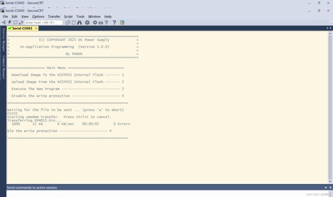
下面是在secureCRT中主菜单和发送完成bin后的界面: