【物联网无线通信技术】ZigBee从理论到实践(CC2530)
文章延续之前【物联网无线通信技术】系列文章的风格,首先对ZigBee这种在物联网发展初期出现的无线通信技术进行了相关背景概念的介绍,并横向介绍了几款时间跨度比较大的ZigBee芯片。然后以CC2530为例,从硬件到软件介绍了ZigBee这中无线通信技术的实现。相信读者通过通读本篇文章,能够对ZigBee无线通信的实现有一个直观的认识。因篇幅有限,本篇中有些概念和功能没有详细展开,读者可以通过文中的外链进行更深的探究。
目录
ZigBee概述
CC2530EM+SmartRF05
例程解析
工程代码结构
Basic RF
Hardware Abstraction Layer
工程编译与下载
ZigBee概述
ZigBee技术是一种短距离无线通信技术,主要的特色有数据传输速率低、功耗低、实现成本低、网络容量大等,常用于智能家居,工业自动化等领域。Zigbee基于IEEE 802.15.4标准,该标准定义了用于低速无线个人局域网(LR-WPANs)的物理层和介质访问控制(MAC)层。Zigbee在此基础上提供了网络层、安全特性和各种用例的应用框架,应用层的开发可以根据用户的应用需要,对其进行灵活的组网、开发利用。常见的ZigBee的工作频段为2.4G,一共具有16个信道11 (2405 MHz) to 26 (2480 MHz),理论上通信速率可达250kbps,采用O-QPSK调制,实际的通信距离取决于发射功率和天线的效率。
下面介绍几款常见的ZigBee芯片厂商。
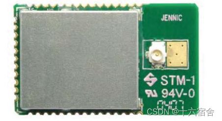
- Jennic (JN5148,已停产):N5148 是一款超低功耗、高性能 MCU,结合了符合 IEEE802.15.4 标准的收发器。它面向低功耗无线网络应用,具有增强型 32 位 RISC 处理器,通过可变宽度指令、多级指令流水线和具有可编程时钟速度和各种睡眠模式的低功耗操作提供高编码效率。该器件包括 128 kB ROM、128 kB RAM 以及丰富的模拟和数字外设组合。大内存占用空间允许该器件既可以运行网络堆栈(如ZigBee PRO或恩智浦专有的JenNet网络堆栈),也可以运行嵌入式应用或协处理器模式。工作电流低于 18 mA,允许直接从纽扣电池工作。
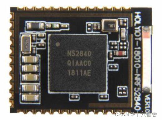
- Nordic(NRF52840):NRF52840是Nordic Semiconductor公司推出的一款多协议无线通信模块,其中包括对Zigbee的支持。它采用了高性能的ARM Cortex-M4处理器,集成了丰富的硬件资源和Zigbee协议栈,适用于高性能和低功耗要求的应用场景。
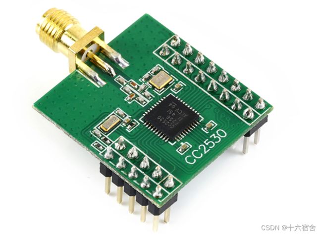
- TI(CC2530)::CC2530是德州仪器(Texas Instruments)推出的一款常用的Zigbee模块。它采用了低功耗的SoC(系统级芯片)设计,集成了Zigbee通信协议栈并结合了领先的射频收发器,采用行业标准增强型 8051 MCU,提供在系统内可编程闪存、8KB大小的RAM和许多其他强大功能。CC2530模块广泛应用于家庭自动化、工业控制和传感器网络等领域。
CC2530EM+SmartRF05
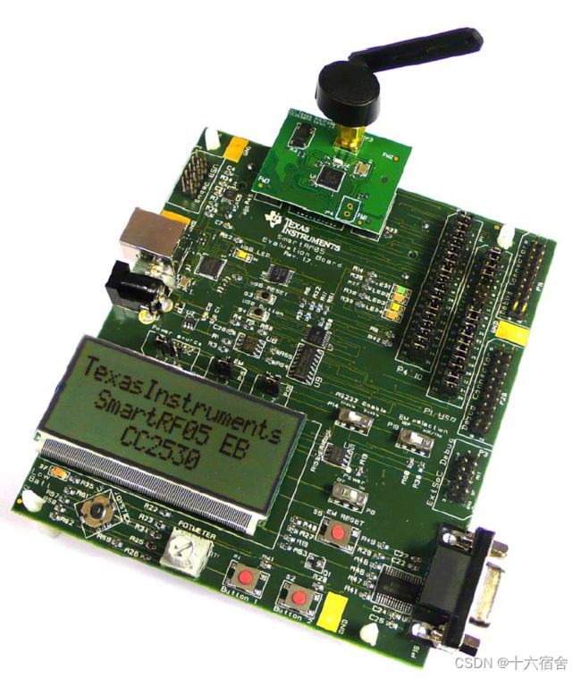
射频板我们使用CC2530EM,它是使用CC2530为核心基于推荐的参考设计实现的完整射频模块。该模块配备一个32 MHz 晶振、一个32.768 kHz 晶振、射频电路上的巴伦和天线匹配滤波器等无源元件以及用于连接天线的SMA 连接器。其相关的参考原理设计可以点击此处跳转。
这里如果需要有更远的传输距离,可以选用CC2530-CC2591EM,它增加了具有高达+22dBm增益的2.4GB射频前端芯片CC2591。
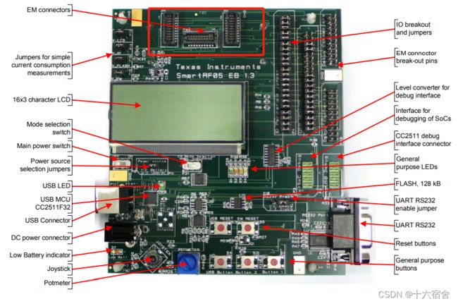
底板我们使用SmartRF05,它能连接多个德州仪器(TI)低功耗射频模块。该板具有广泛的外围接口,例如:
- 3x16字符串行LCD
- 全速USB 2.0接口
- UART
- LED
- Buttons
- Joystick
我们在上图的底板红框处插入射频板,然后通过CC Debug连接到底板即可进行程序下载调试,点击这里跳转底板相关参考设计。
例程解析
Ti官网提供了相关例程供用户评估射频性能,点击这里跳转下载(不要私信博主要代码了,能上传的网络资源均已上传或者在文章中添加链接,具体的项目工程代码绝不会给)。
官网的例程一共包含以下三个功能实现:
- Light/Switch application:这个例程用于实现无线控制LED灯,芯片需要提前刷写‘light_switch’工程 。例程需要两个节点,一个作为无线开关,一个作为无线灯控制器。具体例程的使用过程如下:
- 在底板摁下Button1进入应用程序菜单。
- 选择节点模式。通过向右或向左移动joystick来导航菜单。选择其中一个节点上的设备模式为“Switch”,另一个节点上的设备模式为“Light”。确认选项按Button1。
- LED开关应用示例现已准备就绪。“Light”节点上的 LED1现在可以通过向下移动“Switch”上的joystick来切换。
- Packet Error Rate tester application(PER测试):这个例程需要提前刷写‘per_test’工程,需要两个节点来完成数据报误码率测试,数据包误码率测试应用程序在两个节点之间建立单向射频链路。一块板子将作为发射节点运行,另一块板将作为接收节点运行。发送器节点必须配置了要使用的输出功率和作为 PER 测试的一部分要传输的数据包数(burst size)。在 PER 测试期间,接收方节点将显示接收的数据包数,即 RSSI电平(信号强度)和 PER。发射节点需要配置模式为发送,接收节点配置模式为接收,两者的通道配置需要保持一致。CC2530EM与CC2530-CC2591EM两种不同的射频板提供了不同的配置选项,CC2530-CC2591EM增加了接收增益,并提供了更高的输出功率:
- CC2530EM:Channel=11–26 (2405 – 2480 MHz);Operating Mode=Receiver/Transmitter;TX Output Power=-3dBm/0dBm/4dBm;Burst Size=1K/10K/100K/1M;Packet rate=100, 50, 20 or 10 packets per second。
- CC2530-CC2591EM:Channel=11 – 26 (2405 – 2480 MHz);Operating Mode=Receiver/Transmitter;Receiver gain=High Gain/Low Gain;TX Output Power=0 dBm/13 dBm/16 dBm/18dBm/20 dBm;Burst Size=1K, 10K, 100K, 1M;Packet rate=100, 50, 20 or 10 packets per second。
- Spectrum Analyzer application:此应用程序使用 SmartRF05EB上的LCD显示所有IEEE 802.15.4定义通道(11到26)的RSSI值。应用程序以条形图显示模式启动。在此模式下,只有 16 个通道的条形图显示。条形图范围为-120dBm至-10dBm。文本模式添加文本显示通道号和一个特定通道的测量值,同时仍显示所有通道的条形图,尽管分辨率有所降低。用户可以在通过向上移动joystick来显示模式。在文本模式下,通过移动joystick来选择频道向左或向右。
工程代码结构
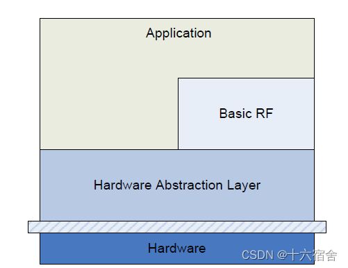
工程代码主要由以下三个部分组成(组件):
- Application layer:该部分包含了上述所示的三种例程实现,可访问到基本RF和HAL。
- Basic RF:提供了一个简单的协议,用于使用双向射频链路实现传输和接收。
- Hardware Abstraction Layer:包含访问片内外设,诸如RF、ADC、定时器等;以及板载的功能外设模块如LCD、UART、操纵杆、按钮。
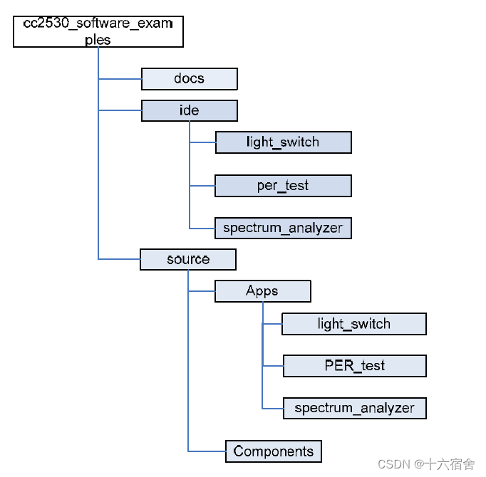
工程的帮助文档位于docs文件夹中。工作区文件位于ide文件夹中。不同应用程序的代码可以在文件夹 source/Apps 中找到。组件文件夹包括应用程序使用的不同组件的源代码。HAL和基本射频
源代码组件位于组件文件夹下。
Basic RF
基本射频层使用双向射频链路提供简单的发射和接收协议。基本射频协议提供数据包传输和接收服务。它还通过使用CCM-64身份验证和数据包加密/解密进行通信,提供安全功能。安全功能的使能可以通过定义编译开关SECURITY_CCM来实现。该协议使用符合IEEE 802.15.4的MAC标准数据包。然而,它不提供完整的MAC层,仅提供用于两个节点之间通信的简单数据链路层。
- Association, scanning or beacons均没有实现。
- 没有定义coordinator/device角色(所有节点平等)。
- 没有报重发。
数据帧如下图所示。
Basic RF的使用主要分为以下三个部分。
- Startup: 确保外设和RF已初始化,即调用halBoardInit()。创建一个basicRfCfg_t结构,并初始化其成员。如果使用Basic RF的安全特性,上层负责分配16字节密钥。调用basicRfInit()初始化数据包协议。
- Transmission:建立一个buffer用于存储要发送的数据,最大为103字节。调用basicRfSendPacket()发送。
- Reception:通过调用 basicRfPacketIsReady()来执行轮询,以检查是否接收到新数据包可以由上层处理。调用basicRfReceive()以接收完成数据包。调用方负责为数据包分配足够大的缓冲区,为RSSI值分配2字节缓冲区空间。
通过调用 basicRfReceiveOn(),无线电接收器将始终保持开启状态。节点能够随时接收数据包,缺点是电流消耗较高。通过调用 basicRfReceiveOff()关闭无线电接收器。
如果需要调用Basic RF层相关API,需要提前包含basic_rf.h与basic_rf_security.h。
下面是结构体与API原型代码,代码中包含API的功能说明。
typedef struct {
    uint16 myAddr;
    uint16 panId;
    uint8 channel;
    uint8 ackRequest;
    #ifdef SECURITY_CCM
    uint8* securityKey;
    uint8* securityNonce;
    #endif
} basicRfCfg_t;

/***********************************************************************************
* GLOBAL FUNCTIONS
*/

/* Initialise basic RF datastructures. Sets channel, short address and PAN ID in the chip and configures interrupt on packet reception. The board peripherals and radio interface must be called before this function with the function halBoardInit(). */
uint8 basicRfInit(basicRfCfg_t* pRfConfig);

/* Send packet to the given destination short address. Returns TRUE if packet was sent
successfully, and FAILED otherwise. If ackRequest is TRUE the return value of this function will only be TRUE if an acknowledgment is received from the destination. */
uint8 basicRfSendPacket(uint16 destAddr, uint8* pPayload, uint8 length);

/* Returns TRUE if a received packet is ready to be retrieved by higher layer. */
uint8 basicRfPacketIsReady(void);

/* Returns the RSSI value of the last received packet */
int8 basicRfGetRssi(void);

/* Retrieve packet from basic RF layer. The caller is responsible for allocating buffer space for data and the RSSI value. */
uint8 basicRfReceive(uint8* pRxData, uint8 len, int16* pRssi);

/*Turn on receiver on radio. After calling this function the radio is kept on until basicRfReceiveOff is called. */
void basicRfReceiveOn(void);

/* Turn off receiver on radio, and keep it off unless for transmitting a packet with Clear Channel Assessment. */
void basicRfReceiveOff(void);
下面的时序图介绍了软件组件在初始化工作中完成的调用流程。
下面的时序图介绍了软件组件在发送工作中完成的调用流程。
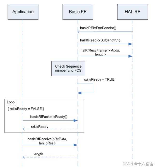
下面的时序图介绍了软件组件在接收工作中完成的调用流程。
最后再次强调以下例程中的Basic RF只是一种非常简单的IEEE 802.15.4实现,它并不完整,建议使用TIMAC或SimplicTI代替 Basic RF进行产品开发。
Hardware Abstraction Layer
要使用HAL组件中的API,需要包含hal_rf.h和hal_rf_security.h。
下面的代码包含此组件涉及的API以及对应的功能说明。
/* Powers up the radio, configures the radio with recommended register settings, enables
autoack and configures the IO on the radio. This function must be called after halBoardInit(). */
uint8 halRfInit(void);

/* Set TX output power */
uint8 halRfSetTxPower(uint8 power);

/* Transmit frame */
uint8 halRfTransmit(void);

/* Set gain mode. This is only used if external LNA/PA is used. */
void  halRfSetGain(uint8 gainMode);     // With CC2590/91 only

/* return radio chip id register */
uint8 halRfGetChipId(void);

/* Return radio chip version register */
uint8 halRfGetChipVer(void);

/* Return random byte. */
uint8 halRfGetRandomByte(void);

/* Return RSSI offset for radio. */
uint8 halRfGetRssiOffset(void);

/

/* Write the number of bytes given by length from the memory location pointed to by the pointer data to the radio TX buffer. */
void  halRfWriteTxBuf(uint8* pData, uint8 length);

/* Read the number of bytes given by length from radio RX buffer to the memory location pointed to by the pointer data. The radio status byte is returned. */
void  halRfReadRxBuf(uint8* pData, uint8 length);

/* Wait until the transceiver is ready */
void  halRfWaitTransceiverReady(void);


/* Turn on receiver on radio. */
void  halRfReceiveOn(void);

/* Turn off receiver on radio. */
void  halRfReceiveOff(void);

/* Clear and disable RX interrupt. */
void  halRfDisableRxInterrupt(void);

/* Enable RX interrupt. */
void  halRfEnableRxInterrupt(void);

/* Configure RX interrupt, and setting the function to be called on interrupt. */
void  halRfRxInterruptConfig(ISR_FUNC_PTR pfISR);

///
// IEEE 802.15.4 specific interface

/* Set RF channel. Channel must be in the range 11-26. */
void  halRfSetChannel(uint8 channel);

/* Write 16 bit short address to the radio. */
void  halRfSetShortAddr(uint16 shortAddr);

/* Write 16 bit PAN ID to the radio. */
void  halRfSetPanId(uint16 PanId);
工程编译与下载
首先,连接好底板和主板,并将开发板与电脑通过USB线连接。
首先确保EM选择开关(SmartRF05EB上的P19)位于SoC/TRX位置,使用IAR打开CC2530_SW_examples.eww。可以看到下图有针对三种不同例程的工程。选择对应工程,然后选择Project->Rebuild All进行代码编译。
此时可以直接通过IAR进行在线仿真调试,也可以通过通过Ti提供Flash Programmer进行hex程序烧写。
十六宿舍 原创作品,转载必须标注原文链接。
©2023 Yang Li. All rights reserved.
欢迎关注 『十六宿舍』,大家喜欢的话,给个,更多关于嵌入式相关技术的内容持续更新中。

