单片机第三季-第六课:STM32标准库
1,为什么会有标准外设库
传统单片机软件开发方式:
(1)芯片厂商提供数据手册、示例代码、开发环境;
(2)单片机软件工程师面向产品功能,查阅数据手册,参考官方示例代码进行开发;
(3)硬件操作的方式是用C语言对寄存器进行读写以操作硬件;
(4)主要工作量分2块:一是调通各种外设,二是实现产品功能;
(5)在简单单片机(如51单片机)上这一套工作的很好,但是随着单片机变复杂就带来一些问题;
外设库有什么价值:
(1)外设库其实就是以前芯片公司提供的示例代码的标准化产物;
(2)外设库简化了我们开发产品的2大工作量的第一个;
(3)外设库以源码方式提供,这个源码本身写的很标准,可以用作学习素材;
学习和使用外设库的难点:
(1)要有规范化编程的意识和能力;
(2)C语言功底要过关;
(3)要有一定的框架和层次认识;
(4)要会没有外设库时直接C语言操作寄存器的方式(看原理图、查数据手册、位操作等);
外设库只是帮助我们简化编程,简化的主要是劳动量。
外设库一定程度上降低了编程难度,但是只会库、离了库就不会编程、库函数调用出了问题就束手无策这种还是没戏。(难度降低是对所有人的,你并不能从中得到好处)
2,标准外设库的结构介绍
如何获取最新版本标准外设库?从意法半导体官网下载。
意法半导体
STM32F10x系列最新版本为3.6.0版本,本文章中使用的是3.5.0版本。
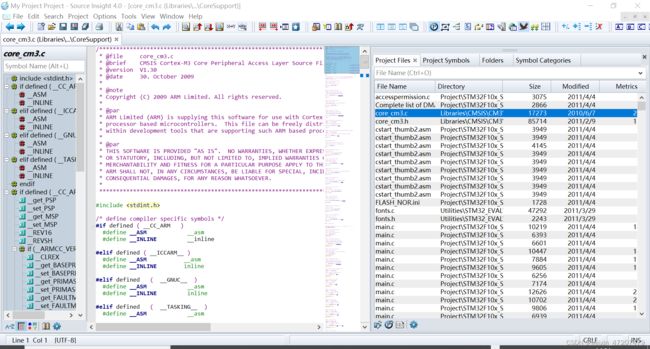
使用SourceInsight软件建立工程查看标准库,SourceInsight软件方便对源码进行查看,具体参考参考嵌入式第二部分《2.3.6.SourceInsight的基本使用》。
标准库文件夹结构和主要文件的作用,主要是Libraries文件夹下的内容,包括CMSIS和STM32F10x_StdPeriph_Driver文件夹:
CMSIS(STM32内部ARM核心相关内容)
CM3(Cortex-M3)
CoreSupport
内核相关的一些设置的寄存器集合及其封装
DeviceSupport
ST
STM32F10x
startup(起始文件)
stm32f10x.h
system_stm32f10x.c
system_stm32f10x.h
STM32F10x_StdPeriph_Driver(外设驱动)
inc(include,头文件,.h)
src(source,源文件, .c)
STM32标准外设库的学习方法:
(1)先搞清楚库对STM32这个硬件的封装和表达方式;
(2)再彻底理解库中使用的结构体式访问硬件寄存器的方式;
(3)初步建立起面向对象式编程的概念并且去体会;
(4)以模块为单位去研究这个模块的库函数,并且用库函数去编程,并且实验结果,并且分析代码,去体会去熟悉库函数使用的方法;
(5)最终达到什么程度?眼里有库心中无库。用人话说就是:思维能够穿透库函数直达内部对寄存器的操作。
3,标准库对硬件信息的封装方式
寄存器地址的封装:
以GPIO为例,查看标准库中如何对寄存器地址封装。
在路径Libraries\CMSIS\CM3\DeviceSupport\ST\STM32F10x中的stm32f10x.h文件中,对GPIO的相关地址进行了定义。
定义了GPIO的基地址:
#define APB1PERIPH_BASE       PERIPH_BASE
#define APB2PERIPH_BASE       (PERIPH_BASE + 0x10000)

#define GPIOA_BASE            (APB2PERIPH_BASE + 0x0800)
#define GPIOB_BASE            (APB2PERIPH_BASE + 0x0C00)
#define GPIOC_BASE            (APB2PERIPH_BASE + 0x1000)
#define GPIOD_BASE            (APB2PERIPH_BASE + 0x1400)
#define GPIOE_BASE            (APB2PERIPH_BASE + 0x1800)
#define GPIOF_BASE            (APB2PERIPH_BASE + 0x1C00)
#define GPIOG_BASE            (APB2PERIPH_BASE + 0x2000)
定义了GPIO寄存器的结构体类型,将GPIO相关的寄存器放到一个结构体类型中:
typedef struct
{
  __IO uint32_t CRL;       //#define     __IO    volatile
  __IO uint32_t CRH;
  __IO uint32_t IDR;
  __IO uint32_t ODR;
  __IO uint32_t BSRR;
  __IO uint32_t BRR;
  __IO uint32_t LCKR;
} GPIO_TypeDef;
把整个一个模块的所有寄存器(地址是连接的)打包在一个结构体中,每个寄存器对应结构体中的一个元素,然后结构体基地址对应寄存器组的基地址,将来就可以通过结构体的各个元素来访问各个寄存器了。
定义了宏定义指针指向结构体:
#define GPIOA               ((GPIO_TypeDef *) GPIOA_BASE)
#define GPIOB               ((GPIO_TypeDef *) GPIOB_BASE)
#define GPIOC               ((GPIO_TypeDef *) GPIOC_BASE)
#define GPIOD               ((GPIO_TypeDef *) GPIOD_BASE)
#define GPIOE               ((GPIO_TypeDef *) GPIOE_BASE)
#define GPIOF               ((GPIO_TypeDef *) GPIOF_BASE)
#define GPIOG               ((GPIO_TypeDef *) GPIOG_BASE)
访问GPIO寄存器的方式:
GPIOA->CRL = 0X0000 0083;4,分析标准库自带的工程模板
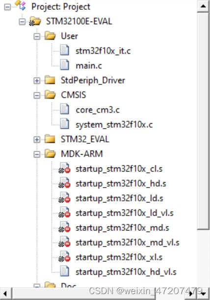
打开标准库路径Project\STM32F10x_StdPeriph_Template\MDK-ARM中的工程模板,工程中主要有下图中几个文件夹,User文件夹中存放用户代码文件,StdPeriph_Driver和CMSIS文件夹中存放的是标准库中的文件,MDK-ARM中存放启动文件。
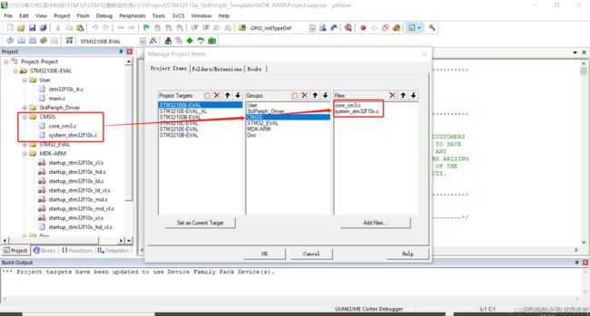
在Manage Project Items选项卡中为工程目录树添加文件夹和文件:
在MDK-ARM中有几个启动文件,如何判断选择哪个启动文件?
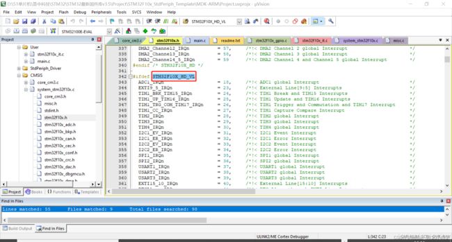
在stm32f10x.h文件中注释有对目标STM32设备属于哪种类型进行了定义:
/*  Tip: To avoid modifying this file each time you need to switch between these
        devices, you can define the device in your toolchain compiler preprocessor.

 - Low-density devices are STM32F101xx, STM32F102xx and STM32F103xx microcontrollers
   where the Flash memory density ranges between 16 and 32 Kbytes.
 - Low-density value line devices are STM32F100xx microcontrollers where the Flash
   memory density ranges between 16 and 32 Kbytes.
 - Medium-density devices are STM32F101xx, STM32F102xx and STM32F103xx microcontrollers
   where the Flash memory density ranges between 64 and 128 Kbytes.
 - Medium-density value line devices are STM32F100xx microcontrollers where the
   Flash memory density ranges between 64 and 128 Kbytes.
 - High-density devices are STM32F101xx and STM32F103xx microcontrollers where
   the Flash memory density ranges between 256 and 512 Kbytes.
 - High-density value line devices are STM32F100xx microcontrollers where the
   Flash memory density ranges between 256 and 512 Kbytes.
 - XL-density devices are STM32F101xx and STM32F103xx microcontrollers where
   the Flash memory density ranges between 512 and 1024 Kbytes.
 - Connectivity line devices are STM32F105xx and STM32F107xx microcontrollers.
  */
在system_stm32f10x.c文件中有两个函数和一个全局变量,是与设置时钟相关的:
This file provides two functions and one global variable to be called from
  *     user application:
  *      - SystemInit(): Setups the system clock (System clock source, PLL Multiplier
  *                      factors, AHB/APBx prescalers and Flash settings).
  *                      This function is called at startup just after reset and
  *                      before branch to main program. This call is made inside
  *                      the "startup_stm32f10x_xx.s" file.
  *
  *      - SystemCoreClock variable: Contains the core clock (HCLK), it can be used
  *                                  by the user application to setup the SysTick
  *                                  timer or configure other parameters.
  *
  *      - SystemCoreClockUpdate(): Updates the variable SystemCoreClock and must
  *                                 be called whenever the core clock is changed
  *                                 during program execution.
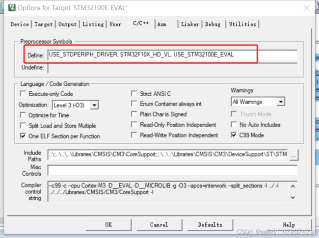
在Options for Target选项卡中定义全局宏定义,可以不用修改源代码中的宏定义:
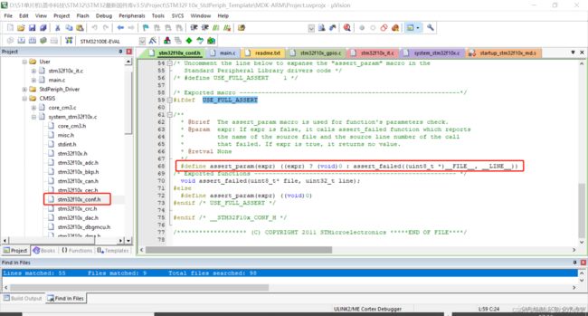
stm32f10x_conf.h文件中定义了一个断言函数,stm32f10x_conf.h文件是这个工程模板提供的,不是标准库中的文件:
5,RCC模块的标准库
以标准库中stm32f10x_rcc文件中的内容进行分析。
下边代码中对寄存器地址对应的位带地址进行定义:
/* Alias word address of HSION bit */
#define CR_OFFSET                 (RCC_OFFSET + 0x00)
#define HSION_BitNumber           0x00
#define CR_HSION_BB               (PERIPH_BB_BASE + (CR_OFFSET * 32) + (HSION_BitNumber * 4))
对某一位操作值得宏定义,Reset代表将一位置0,其它位不变,Set代表将一位置1,其它位不变:
/* CR register bit mask */
#define CR_HSEBYP_Reset           ((uint32_t)0xFFFBFFFF)
#define CR_HSEBYP_Set             ((uint32_t)0x00040000)
#define CR_HSEON_Reset            ((uint32_t)0xFFFEFFFF)
#define CR_HSEON_Set              ((uint32_t)0x00010000)
#define CR_HSITRIM_Mask           ((uint32_t)0xFFFFFF07)
HSE寄存器的设置函数,设置外部高速晶振,以下标准库代码中包括对该函数的介绍,,注意事项,函数输入参数介绍和类型,返回值:
/**
  * @brief  Configures the External High Speed oscillator (HSE).
  * @note   HSE can not be stopped if it is used directly or through the PLL as system clock.
  * @param  RCC_HSE: specifies the new state of the HSE.
  *   This parameter can be one of the following values:
  *     @arg RCC_HSE_OFF: HSE oscillator OFF
  *     @arg RCC_HSE_ON: HSE oscillator ON
  *     @arg RCC_HSE_Bypass: HSE oscillator bypassed with external clock
  * @retval None
  */
void RCC_HSEConfig(uint32_t RCC_HSE)
{
  /* Check the parameters */
  assert_param(IS_RCC_HSE(RCC_HSE));
  /* Reset HSEON and HSEBYP bits before configuring the HSE ------------------*/
  /* Reset HSEON bit */
  RCC->CR &= CR_HSEON_Reset;
  /* Reset HSEBYP bit */
  RCC->CR &= CR_HSEBYP_Reset;
  /* Configure HSE (RCC_HSE_OFF is already covered by the code section above) */
  switch(RCC_HSE)
  {
    case RCC_HSE_ON:
      /* Set HSEON bit */
      RCC->CR |= CR_HSEON_Set;
      break;

    case RCC_HSE_Bypass:
      /* Set HSEBYP and HSEON bits */
      RCC->CR |= CR_HSEBYP_Set | CR_HSEON_Set;
      break;

    default:
      break;
  }
}
通过函数参数可以设置将HSE关闭、打开、或使用外部晶振电路。
HSE设置函数中以下代码的含义即为打开HSE Bypass,即使用外部晶振电路:
    case RCC_HSE_Bypass:
      /* Set HSEBYP and HSEON bits */
      RCC->CR |= CR_HSEBYP_Set | CR_HSEON_Set;
对应数据手册中的以下内容:
外部时钟源(HSE旁路) 在这个模式里,必须提供外部时钟。它的频率最高可达25MHz。用户可通过设置在时钟控制寄存器中的HSEBYP和HSEON位来选择这一模式。
  /* Check the parameters */
  assert_param(IS_RCC_HSE(RCC_HSE));
断言函数,对输入的参数进行校验,是否符合要求,在文件stm32f10x_conf.h中通过宏定义可以打开或关闭断言函数:
/* Exported macro ------------------------------------------------------------*/
#ifdef  USE_FULL_ASSERT

/**
  * @brief  The assert_param macro is used for function's parameters check.
  * @param  expr: If expr is false, it calls assert_failed function which reports
  *         the name of the source file and the source line number of the call
  *         that failed. If expr is true, it returns no value.
  * @retval None
  */
  #define assert_param(expr) ((expr) ? (void)0 : assert_failed((uint8_t *)__FILE__, __LINE__))
/* Exported functions ------------------------------------------------------- */
  void assert_failed(uint8_t* file, uint32_t line);
#else
  #define assert_param(expr) ((void)0)
#endif /* USE_FULL_ASSERT */
6,使用标准库控制LED
使用标准库编写控制LED闪烁的代码,并通过设置时钟实现LED的闪烁频率发生变化。
注意时钟函数中有个需要设置flash相关的环节参考示例代码。
在搭建此工程时,在编译工程时出现以下错误提示:
先尝试使用标准库点亮LED
点亮LED使用标准库函数,并封装为单独的led.c和led.h文件:
#ifndef _led_H
#define _led_H

#include "stm32f10x.h"

/*  LED时钟端口、引脚定义 */
#define LED_PORT 			GPIOA
#define LED_PIN 			GPIO_Pin_0
#define LED_PORT_RCC		RCC_APB2Periph_GPIOA


void LED_Init(void);


#endif
#include "led.h"

/*******************************************************************************
* 函 数 名         : LED_Init
* 函数功能		   : LED初始化函数
* 输    入         : 无
* 输    出         : 无
*******************************************************************************/
void LED_Init()
{
	GPIO_InitTypeDef GPIO_InitStructure;//定义结构体变量

	RCC_APB2PeriphClockCmd(LED_PORT_RCC,ENABLE);

	GPIO_InitStructure.GPIO_Pin=LED_PIN;  //选择你要设置的IO口
	GPIO_InitStructure.GPIO_Mode=GPIO_Mode_Out_PP;	 //设置推挽输出模式
	GPIO_InitStructure.GPIO_Speed=GPIO_Speed_50MHz;	  //设置传输速率
	GPIO_Init(LED_PORT,&GPIO_InitStructure); 	   /* 初始化GPIO */

	GPIO_ResetBits(LED_PORT,LED_PIN);   //将LED端口拉高,熄灭所有LED
}
在main文件中包含#include "led.h",main.c文件:
#include "stm32f10x.h"
#include "led.h"

void delay(void);

int main()
{
	LED_Init();
	while(1)
	{
		GPIO_SetBits(LED_PORT,LED_PIN);
		delay();
		GPIO_ResetBits(LED_PORT,LED_PIN);
		delay();
	}
}

void delay(void)
{
    unsigned char a,b,c;
     for(c=207;c>0;c--)
        for(b=58;b>0;b--)
            for(a=113;a>0;a--);
}
在开发板上运行代码,实验现象为LED闪烁。
7,使用标准库设置RCC
使用标准库设置RCC时钟频率,实现LED闪烁频率发生改变。
待完善,主要是使用RCC标准模块设置时钟频率。


