MPLS-虚拟专用网部署
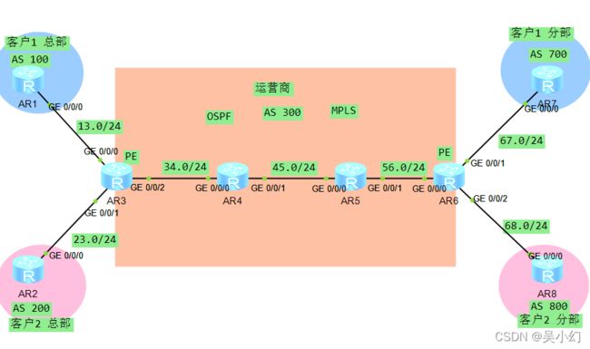
MPLS-虚拟专用网是指采用MPLS技术在运营商宽带IP网络上构建企业IP专网,实现跨地域、安全、高速、可靠的数据、语音、图像多业务通信,并结合差别服务、流量工程等相关技术,将公众网可靠的性能、良好的扩展性、丰富的功能与专用网的安全 、灵活、高效结合在一起,为用户提供高质量的服务
一、配置思路
1、配置网路基本IP信息
2、配置IGP-OSPF协议
3、配置BGP协议
4、配置MPLS
5、配置MPLS-虚拟专用网
6、测试
二、代码演示
1、配置网路基本IP信息
R1:
interface GigabitEthernet0/0/0
ip address 192.168.13.1 255.255.255.0
#
interface LoopBack0
ip address 10.10.1.1 255.255.255.255
R2:
interface GigabitEthernet0/0/0
ip address 192.168.23.2 255.255.255.0
#
interface LoopBack0
ip address 10.10.2.2 255.255.255.255
R3:
interface GigabitEthernet0/0/0
ip address 192.168.13.3 255.255.255.0
#
interface GigabitEthernet0/0/1
ip address 192.168.23.3 255.255.255.0
#
interface GigabitEthernet0/0/2
ip address 192.168.34.3 255.255.255.0
#
interface LoopBack0
ip address 10.10.3.3 255.255.255.255
R4:
interface GigabitEthernet0/0/0
ip address 192.168.34.4 255.255.255.0
#
interface GigabitEthernet0/0/1
ip address 192.168.45.4 255.255.255.0
#
interface LoopBack0
ip address 10.10.4.4 255.255.255.255
R5:
interface GigabitEthernet0/0/0
ip address 192.168.45.5 255.255.255.0
#
interface GigabitEthernet0/0/1
ip address 192.168.56.5 255.255.255.0
#
interface LoopBack0
ip address 10.10.5.5 255.255.255.255
R6:
interface GigabitEthernet0/0/0
ip address 192.168.56.6 255.255.255.0
#
interface GigabitEthernet0/0/1
ip address 192.168.67.6 255.255.255.0
#
interface GigabitEthernet0/0/2
ip address 192.168.68.6 255.255.255.0
#
interface LoopBack0
ip address 10.10.6.6 255.255.255.255
R7:
interface GigabitEthernet0/0/0
ip address 192.168.67.7 255.255.255.0
#
interface LoopBack0
ip address 10.10.7.7 255.255.255.255
R8:
interface GigabitEthernet0/0/0
ip address 192.168.68.8 255.255.255.0
#
interface LoopBack0
ip address 10.10.8.8 255.255.255.255
2、配置IGP-OSPF协议
R3:
[r3]ospf 1 router-id 3.3.3.3
[r3-ospf-1]area 0
[r3-ospf-1-area-0.0.0.0]network 192.168.34.0 0.0.0.255
[r3-ospf-1-area-0.0.0.0]network 10.10.3.3 0.0.0.0
R4:
[r4]ospf 1 router-id 4.4.4.4
[r4-ospf-1]area 0
[r4-ospf-1-area-0.0.0.0]network 192.168.34.0 0.0.0.255
[r4-ospf-1-area-0.0.0.0]network 192.168.45.0 0.0.0.255
[r4-ospf-1-area-0.0.0.0]network 10.10.4.4 0.0.0.0
R5:
[r5]ospf 1 router-id 5.5.5.5
[r5-ospf-1]area 0
[r5-ospf-1-area-0.0.0.0]network 192.168.45.0 0.0.0.255
[r5-ospf-1-area-0.0.0.0]network 192.168.56.0 0.0.0.255
[r5-ospf-1-area-0.0.0.0]network 10.10.5.5 0.0.0.0
R6:
[r6]ospf 1 router-id 6.6.6.6
[r6-ospf-1]area 0
[r6-ospf-1-area-0.0.0.0]network 192.168.56.0 0.0.0.255
[r6-ospf-1-area-0.0.0.0]network 10.10.6.6 0.0.0.0
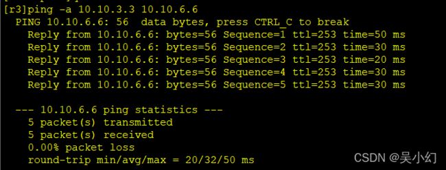
测试ospf区域连通
3、配置BGP协议
R1:
[r1]bgp 100
[r1-bgp]router-id 1.1.1.1
[r1-bgp]peer 192.168.13.3 as-number 300
[r1-bgp]network 10.10.1.1 32 //宣告路由信息注入BGP
R2:
[r2]bgp 200
[r2-bgp]router-id 2.2.2.2
[r2-bgp]peer 192.168.23.3 as-number 300
[r2-bgp]network 10.10.2.2 32
R3:
[r3]bgp 300
[r3-bgp]router-id 3.3.3.3
[r3-bgp]peer 192.168.13.1 as-number 100
[r3-bgp]peer 192.168.23.2 as-number 200
[r3-bgp]peer 10.10.6.6 as-number 300
[r3-bgp]peer 10.10.6.6 connect-interface LoopBack 0
[r3-bgp]peer 10.10.6.6 next-hop-local
R6:
[r6]bgp 300
[r6-bgp]router-id 6.6.6.6
[r6-bgp]peer 192.168.67.7 as-number 700
[r6-bgp]peer 192.168.68.8 as-number 800
[r6-bgp]peer 10.10.3.3 as-number 300
[r6-bgp]peer 10.10.3.3 connect-interface LoopBack 0
[r6-bgp]peer 10.10.3.3 next-hop-local
R7:
[r7]bgp 700
[r7-bgp]router-id 7.7.7.7
[r7-bgp]peer 192.168.67.6 as-number 300
[r7-bgp]network 10.10.7.7 32
R8:
[r8]bgp 800
[r8-bgp]router-id 8.8.8.8
[r8-bgp]peer 192.168.68.6 as-number 300
[r8-bgp]network 10.10.8.8 32
4、配置MPLS
(1)全局配置LSR-ID----建议采用逻辑接口,比较稳定
(2)全局开启MPLS
(3)全部开启LDP
(4)参与MPLS 计算的接口开启MPLS /MPLS LDP
(5)在LER标签的边缘路由器上,配置IP协议与标签转换
R3:
[r3]mpls lsr-id 10.10.3.3
[r3]mpls
[r3-mpls]mpls ldp
[r3]int g0/0/2
[r3-GigabitEthernet0/0/2]mpls
[r3-GigabitEthernet0/0/2]mpls ldp
[r3]route recursive-lookup tunnel //将IP报文转换到隧道
R4:
[r4]mpls lsr-id 10.10.4.4
[r4]mpls
[r4]mpls ldp
[r4]int g0/0/0
[r4-GigabitEthernet0/0/0]mpls
[r4-GigabitEthernet0/0/0]mpls ldp
[r4]int g0/0/1
[r4-GigabitEthernet0/0/1]mpls
[r4-GigabitEthernet0/0/1]mpls ldp
R5:
[r5]mpls lsr-id 10.10.5.5
[r5]mpls
[r5]mpls ldp
[r5]int g0/0/0
[r5-GigabitEthernet0/0/0]mpls
[r5-GigabitEthernet0/0/0]mpls ldp
[r5]int g0/0/1
[r5-GigabitEthernet0/0/1]mpls
[r5-GigabitEthernet0/0/1]mpls ldp
R6:
[r6]mpls lsr-id 10.10.6.6
[r6]mpls
[r6]mpls ldp
[r6]int g0/0/0
[r6-GigabitEthernet0/0/0]mpls
[r6-GigabitEthernet0/0/0]mpls ldp
[r6]route recursive-lookup tunnel //将IP报文转换到隧道
5、配置MPLS-虚拟专用网
(1)在PE设备上创建VRF表
[r3]ip -instance 1
[r3--instance-1]ipv4-family
[r3]int g0/0/0
[r3-GigabitEthernet0/0/0]ip binding -instance 1
[r3-GigabitEthernet0/0/0]ip ad 192.168.13.3 24
[r3]ip -instance 2
[r3--instance-2]ipv4-family
[r3]int g0/0/1
[r3-GigabitEthernet0/0/1]ip binding -instance 2
[r3-GigabitEthernet0/0/1]ip ad 192.168.23.3 24
[r6]ip -instance 1
[r6--instance-1]ipv4-family
[r6]int g0/0/1
[r6-GigabitEthernet0/0/1]ip binding -instance 1
[r6-GigabitEthernet0/0/1]ip ad 192.168.67.6 24
[r6]ip -instance 2
[r6--instance-2]ipv4-family
[r6]int g0/0/2
[r6-GigabitEthernet0/0/2]ip binding -instance 2
[r6-GigabitEthernet0/0/2]ip ad 192.168.68.6 24
(2)实现PE与CE的专线1互通
架构图左侧配置:
[r1]ip route-static 0.0.0.0 0.0.0.0 192.168.13.3 //在CE端配置指向PE的默认路由
[r3]ip route-static -instance 1 10.10.1.1 32 192.168.13.1 //在PE端 配置静态路由 ,将路由加入VRF表中 ,而不是全局路由表
架构图右侧配置:
[r6]ip route-static -instance 1 10.10.7.7 32 192.168.67.7
[r7]ip route-static 0.0.0.0 0.0.0.0 192.168.67.6
(3)实现PE与CE的专线2互通
架构图左侧配置:
[r3]ip route-static -instance 2 10.10.2.2 32 192.168.23.2
[r2]ip route-static 0.0.0.0 0.0.0.0 192.168.23.3
架构图右侧配置:
[r6]ip route-static -instance 2 10.10.8.8 32 192.168.68.8
[r8]ip route-static 0.0.0.0 0.0.0.0 192.168.68.6
(4) 配置专线客户的 RD 值 ;RT值
注意:RD值 全局唯一 ; RT 是双向的 ,本端的出等于对端的入;本端的入等于对端的出;
[r3]ip -instance 1
[r3--instance-1]route-distinguisher 1:1 //配置RD 比值 ,全局唯一
[r3--instance-1]-target 100:11 export-extcommunity //本端的出向值等于对端的入向值
[r3--instance-1]-target 11:100 import-extcommunity //本端的入向值等于对端的出向值
[r6]ip -instance 1
[r6--instance-1]route-distinguisher 1:1
[r6--instance-1]-target 100:11 import-extcommunity
[r6--instance-1]-target 11:100 export-extcommunity
[r3]ip -instance 2
[r3--instance-2]route-distinguisher 2:2
[r3--instance-2]-target 200:22 export-extcommunity
[r3--instance-2]-target 22:200 import-extcommunity
[r6]ip -instance 2
[r6--instance-2]route-distinguisher 2:2
[r6--instance-2]-target 200:22 import-extcommunity
[r6--instance-2]-target 22:200 export-extcommunity
(5) 建立MP-BPG的邻居关系
[r3]bgp 300
[r3-bgp]ipv4-family unicast //进入到IPV4单播视图 ,关闭邻居关系功能
[r3-bgp-af-ipv4]undo peer 10.10.6.6 enable
[r3-bgp]ipv4-family v4 //进入到VPNV4 协议视图 ,开启邻居关系功能
[r3-bgp-af-v4]peer 10.10.6.6 enable
[r6]bgp 300
[r6-bgp]ipv4-family unicast
[r6-bgp-af-ipv4]undo peer 10.10.3.3 enable
[r6-bgp]ipv4-family v4
[r6-bgp-af-v4]peer 10.10.3.3 enable
(6)将专线1/2 虚拟路由表VRF 里的 路由注入进 MP-BGP 路由表里
[r3]bgp 300
[r3-bgp]ipv4-family -instance 1
[r3-bgp-1]network 10.10.1.1 32
[r3-bgp]ipv4-family -instance 2
[r3-bgp-2]network 10.10.2.2 32
[r6]bgp 300
[r6-bgp]ipv4-family -instance 1
[r6-bgp-1]network 10.10.7.7 32
[r6-bgp]ipv4-family -instance 2
[r6-bgp-2]network 10.10.8.8 32
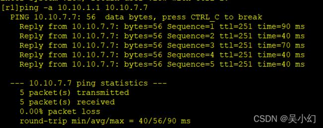
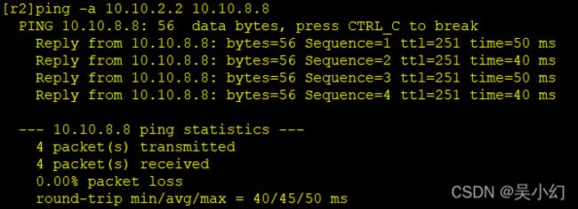
6、验证
[r1]ping -a 10.10.1.1 10.10.7.7
[r2]ping -a 10.10.2.2 10.10.8.8


