Vector CANOE VT2004A配置详解
Vector CANoe CAPL系列相关文章导览,下面链接可直接跳转
- CAPL入门到精通文章导览
Vector CANoe VT System系列板卡文章导览,下面链接可直接跳转
- Vector CANoe VT system传送门
文章目录
- 引言
-
- 关于VT2004A FPGA
- VT2004A前面板和后面板
- Usage
-
- Basic Connection Scheme
-
- Connecting the ECU
- Signal Path Switching
- bus bars
- decade resistor
- Voltage stimulation
- 接插件定义
- Technical Data VT2004A
-
- General
- Input Signals and Switches
- Voltage Stimulation
- Decade Resistor
-
- channel 1-3
- channel 4
- PWM Generation
- 总结
- 实例
-
- 基础功能
-
- VT System Configuration
- VT System Control
- 查看System Variables
- 创建User-defined variables
- 制作panel
- 编写capl脚本
-
- 模式枚举出来
- 设置模式和参数
- 切换为ShortCircuit
- 切换为Resistance
- 切换为Voltage
- 切换为Frequency
- 项目实例
- 公众号
引言
上次写完VT7001A之后,业务需要被迫学习了一下python写网站,耽误了一些时间,后面单独写写python的心得~~~
上一章节我们聊了VT7001A,话不多说,本章介绍VT2004A板卡,板卡详细内容见VT_System_Manual_EN.pdf,内容为个人理解,如有错误,欢迎指正
The Stimulation Module VT2004A is connected to up to four inputs of an ECU, which are connected in real invehicle operation to sensors such as temperature probes or switches. The VT2004A outputs signals to the ECU to simulate sensors and thus to stimulate the ECU. It provides several features to check the ECU behavior regarding these four ECU inputs
- Sensor simulation by output of an analog signal, a PWM signal, or a resistance (decade resistor)
- Simulation of a potentiometer (channel 1 only)
- Relays to connect the ECU input to the original sensor
- Relays to generate electrical errors like short circuits between the ECU output lines and ECU ground or V b a t t V_{batt} Vbatt
总结一下
就是说VT2004A板卡有4个模式,
- short circuit mode/ 模拟短地、电源短接
- decade resistor/ 模拟电阻
- voltage generator/ 模拟电压
- pwm output mode/ 模拟PWM
此外channel 1 还支持模拟电位器–电压表
关于VT2004A FPGA
手上暂时没有这个板卡,等遇到了再补充
有关电路相关基础知识,这里不详细说明,有问题后台私聊交流,等有时间出一期关于硬件电路的文章
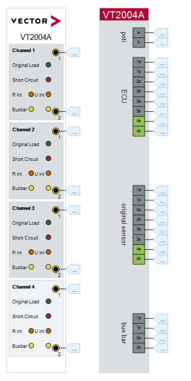
VT2004A前面板和后面板
Usage
Basic Connection Scheme
Connecting the ECU
每个VT2004A有4个通道,每个通道有两个接线端,和ECU通过这两个接线端连接,即使ECU只有一个输入引脚,也必须采用双线连接,这种情况下,传感器的地接到另一个引脚上。
典型应用场景:
| PIN A | PIN B | |
|---|---|---|
| Reference potential ground | ECU input | Ground(ECU ground!) |
| Reference potential V b a t t V_{batt} Vbatt | V b a t t V_{batt} Vbatt | ECU input |
Signal Path Switching
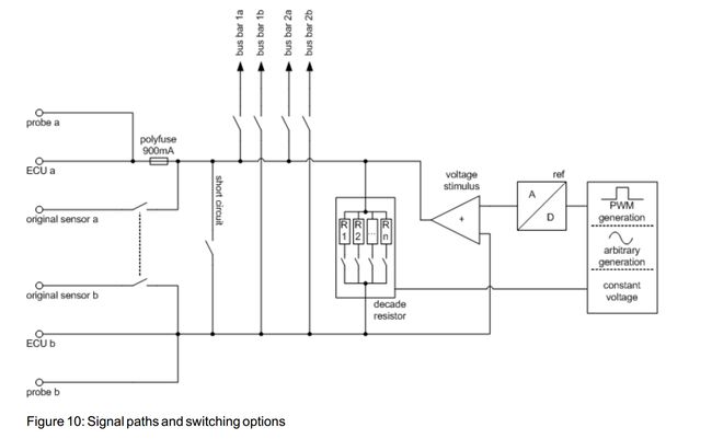
有电路基础的这个图就一目了然了,上面说的几种模式这个图很清晰
每个通道的电路如此,每个VT2004A板卡有这样的4个通道
bus bars

Typically, bus bar 1 is connected to ECU V b a t t V_{batt} Vbatt and ECU ground. This makes it possible to generate short-circuits of channel lines to V b a t t V_{batt} Vbatt and ground. But bus bar 1 may also be used for other purposes.
At the VT2004A the two relays of each bus bar to switch the polarity of the bus bar (bus bar switch relays) can be switched independently. This makes it possible, for instance, to apply the signal at bus bar connection b to both internal bus bar lines (relayais switched →ab). For example, channel lines a and b can both be shorted to ground in this way.
The maximum permissible load for the bus signal paths and relays corresponds to the values given for the channel switching options
这里官方给了一个典型应用场景, bus bar 1 分别接ECU电和ECU地,这样就可以分别测试对电和对地短路了
bus bar a和b分别存在两个继电器,用于bus bar极性的切换,这里官方也给了一个典型场景,继电器都切到b,这样a和b都可以短路到地,这样就可以同时测试a和b短路到地的情况
decade resistor
Decade resistors Each channel contains a decade resistor that can be used to simulate sensors whose
resistance value or current flow change depending on the measurement parameter used. The decade resistor
on channel 4 accommodates a larger value range.
通道4的阻值区间更大
两个模式
- R>
- R<
就是字面意思
这里的电阻矩阵是通过POMS来切换的,所以它无极性,相当于是一个无极性负载去分压。
注意不能不超过功率限制,比如用一个大电压,而阻值很小,这样会损坏板卡
Voltage stimulation
Each of the VT2004 channels provides a unit for generating voltage signals which can be used to simulate sensors that output their measurement values as voltage values.
模拟量输出–电压输出
The specified voltage is delivered as voltage to line
aand applied to lineb. Line b does not need to have ground potential in this case. The voltage output at linebmust always be balanced against the ECU ground within a range of 0 V and the maximum output voltage. Independent from the potential connected to pinb, the maximum output voltage cannot exceed the output range.
看最开始的那张电路图!!
接插件定义
看手册4.4章节
Technical Data VT2004A
手册中都有,这里再贴一下
General

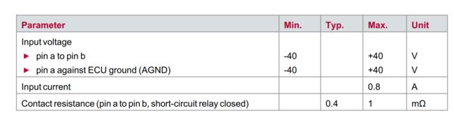
Input Signals and Switches
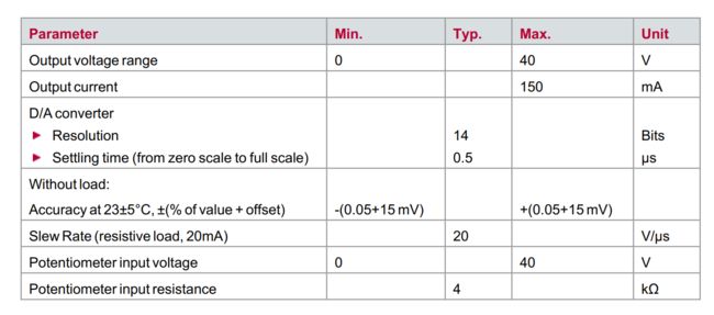
Voltage Stimulation
Decade Resistor
channel 1-3

channel 4

和channel 1-3参数区别在于电阻区间不一样,更大一些
PWM Generation

频率最大200kHz,精度、占空比范围、占空比容差均由频率影响
总结
综上,VT2004A主要是信号激励板卡,提供几种类型的信号输出仿真,每路通道均可作为任意波形发生器使用,同时可以使用继电器控制通断和故障注入。
典型应用场景
- 模拟母线电压
- 模拟IGBT
- 模拟三相电流
- 模拟电机温度
- 模拟水温
- 模拟电池温度
- 模拟电池电压
- 模拟故障注入–对电对地短路
- …
实例
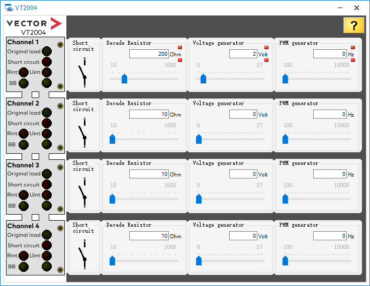
基础功能
功能:
- short circuit
- Decade Resistor
- Voltage Generator
- PWM Generator
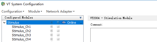
VT System Configuration
连接板卡,不知道咋操作的,看上一篇VT7001A里面有详细说明
VT System Control
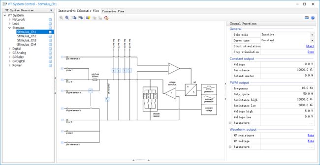
mode都设置为Inactive,Curve type设置为Constant,通过CAPL脚本来实现控制

查看System Variables

创建User-defined variables
根据需要创建如下variables以便于后续panel和capl进行调用

制作panel
编写capl脚本
模式枚举出来
variables
{
  // Defines the modes in which each channel can be
  enum VT2004Modes { None, ShortCircuit, DecadeResistor, VoltageGenerator, PWMGenerator };

  // Stores the mode in which each channel is
  enum VT2004Modes VT2004Ch1Mode = None;
  enum VT2004Modes VT2004Ch2Mode = None;
  enum VT2004Modes VT2004Ch3Mode = None;
  enum VT2004Modes VT2004Ch4Mode = None;
}
设置模式和参数
编写一个函数用于切换通道模式,下面函数细节只写了channel 1,其他通道类似
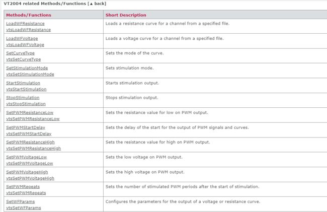
VT2004A相关函数(搜索这个文件CAPLfunctionsVTSystemOverview.htm,有详细介绍,包括函数使用示例等)
switchModeVT2004 ( int channel, enum VT2004Modes mode )
{
    if( channel == 1 )
    {
        if( VT2004Ch1Mode != mode )
        {
            VT2004Ch1Mode = mode;
            if( mode == ShortCircuit )
            {
                sysvar::VTS::Stimulus_Ch1.StopStimulation();
            }
            else if( mode == DecadeResistor )
            {
                // Configure VT module channel as a decade resistor
                // See the CANoe help for details
                sysvar::VTS::Stimulus_Ch1.StopStimulation();
                sysvar::VTS::Stimulus_Ch1.SetStimulationMode(3); // 0: not active;1: Voltage stimulation;2: Potentiometer stimulation(VT2004 only);3: Resistance stimulation R>(VT2004 only);4: Resistance stimulation R<(VT2004 only);
                sysvar::VTS::Stimulus_Ch1.SetCurveType(0);
                sysvar::VTS::Stimulus_Ch1.StartStimulation();
                @sysvar::VT2004::Ch1_ResistorLEDActive = 1;
                @sysvar::VT2004::Ch1_VoltageLEDActive = 0;
            }
            else if( mode == VoltageGenerator )
            {
                // Configure VT module channel as a voltage generator
                // See the CANoe help for details
                sysvar::VTS::Stimulus_Ch1.StopStimulation();
                sysvar::VTS::Stimulus_Ch1.SetStimulationMode(1);
                sysvar::VTS::Stimulus_Ch1.SetCurveType(0);
                sysvar::VTS::Stimulus_Ch1.StartStimulation();
                @sysvar::VT2004::Ch1_ResistorLEDActive = 0;
                @sysvar::VT2004::Ch1_VoltageLEDActive = 1;
            }
            else if( mode == PWMGenerator )
            {
                // Configure VT module channel as a PWM generator
                // See the CANoe help for details
                sysvar::VTS::Stimulus_Ch1.StopStimulation();
                sysvar::VTS::Stimulus_Ch1.SetStimulationMode(1);
                sysvar::VTS::Stimulus_Ch1.SetCurveType(1);
                @sysvar::VTS::Stimulus_Ch1::PWMFreq = 100;
                sysvar::VTS::Stimulus_Ch1.SetPWMVoltageLow(0.0);
                sysvar::VTS::Stimulus_Ch1.SetPWMVoltageHigh(5.0);
                @sysvar::VTS::Stimulus_Ch1::PWMDC = 40;
                sysvar::VTS::Stimulus_Ch1.StartStimulation();
                @sysvar::VT2004::Ch1_ResistorLEDActive = 0;
                @sysvar::VT2004::Ch1_VoltageLEDActive = 1;
            }//end if
        }//end if
    }
    else if (channel == 2)
    {
    // add code ....
    }
}
切换为ShortCircuit
on sysvar sysvar::VT2004::Ch1_ShortCircuit
{
  // Go to short circuit mode on this channel (switchMode function handles the VT configuration change)
  switchModeVT2004( 1, ShortCircuit );
  // Send setting from the panel to the VT module
  @sysvar::VTS::Stimulus_Ch1::RelayShortCircuit = @sysvar::VT2004::Ch1_ShortCircuit;
}
切换为Resistance
on sysvar sysvar::VT2004::Ch1_Resistance
{
  // Activate the decade resistor on this channel (switchMode function handles the VT configuration change)
  switchModeVT2004( 1, DecadeResistor );
  // Send setting from the panel to the VT module
  @sysvar::VTS::Stimulus_Ch1::Resistor = @sysvar::VT2004::Ch1_Resistance;
}
切换为Voltage
on sysvar sysvar::VT2004::Ch1_Voltage
{
  // Activate the voltage generator on this channel (switchMode function handles the VT configuration change)
  switchModeVT2004( 1, VoltageGenerator );
  // Send setting from the panel to the VT module
  @sysvar::VTS::Stimulus_Ch1::Voltage = @sysvar::VT2004::Ch1_Voltage;
}
切换为Frequency
on sysvar sysvar::VT2004::Ch1_Frequency
{
  // Go to PWM output mode on this channel (switchMode function handles the VT configuration change)
  switchModeVT2004( 1, PWMGenerator );
  // Send setting from the panel to the VT module
  @sysvar::VTS::Stimulus_Ch1::PWMFreq  = @sysvar::VT2004::Ch1_Frequency;
}
编译返回canoe主界面测试,在测试前请先确认接线!!!
项目实例
根据实际工况进行处理,不外乎上面的几种情况,如有问题,请关注,点赞,收藏,后台私信~~~
当前使用场景也比较单一,文中可能有部分内容未提及,或有误,请指出,谢谢!
公众号
欢迎关注公众号,发送入群加入专业技术交流。