22、STM32——SPI
1、SPI 简介
SPI 一般有四根通信线,一根时钟线(SCLK)用来从主设备发出时钟脉冲,两根单向数据线(MOSI,MISO)实现全双工通信,一根片选信号由主设备发出,作为从设备的使能信号。
SPI 通信是以主设备发起字节开始的,即便主设备只需要读取从设备发出的数据,也需要先发送字节开启通信的传输。主设备和从设备中各有一个移位寄存器,主设备把要发送的数据写入寄存器,寄存器再通过 MOSI 信号线将数据发送给从设备,与此同时,从设备的数据也从 MISO 信号线传输给主设备。
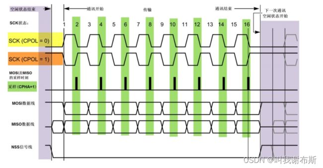
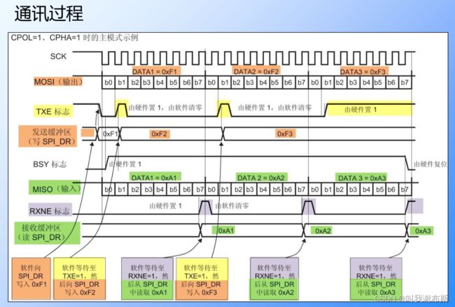
时钟极性:CPOL = 0 串行同步时钟的空闲状态为低电平,CPOL = 1 串行同步时钟的空闲状态为高电平。
时钟相位:CPHA = 0 串行同步时钟的第一个(奇数个)跳变沿数据被采样,CPHA = 1 串行同步时钟的第二个(偶数个)跳变沿数据被采样
当发送完一帧数据的时候,“状态寄存器 SR” 中的 “TXE 标志位” 会被置 1,表示传输完一帧,发送缓冲区已空
当接收完一帧数据的时候,“RXNE 标志位” 会被置 1,表示传输完一帧,接收缓冲区非空
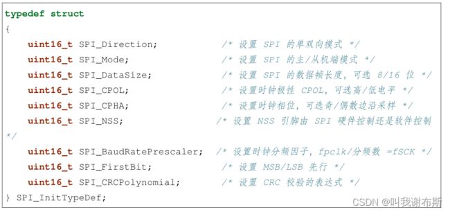
(1) SPI_Direction
设置 SPI 的通讯方向,可设置为双线全双工 (SPI_Direction_2Lines_FullDuplex),双线只接收 (SPI_Direction_2Lines_RxOnly),单线只接收 (SPI_Direction_1Line_Rx)、单线只发送模式
(SPI_Direction_1Line_Tx)
(2) SPI_Mode
设置 SPI 工作在 主机模式 (SPI_Mode_Master) 或 从机模式 (SPI_Mode_Slave ),这两个模式的最大区别为 SPI 的 SCK 信号线的时序,SCK 的时序是由通讯中的主机产生的。若被配置为从机模式,STM32 的 SPI 外设将接受外来的 SCK 信号
(3) SPI_DataSize
本成员可以选择 SPI 通讯的数据帧大小是为 8 位 (SPI_DataSize_8b) 还是 16 位 (SPI_DataSize_16b)。
(4) SPI_CPOL 和 SPI_CPHA
时钟极性 CPOL 成员,可设置为高电平 (SPI_CPOL_High) 或低电平 (SPI_CPOL_Low )
时钟相位 CPHA 则可以设置为 SPI_CPHA_1Edge(在 SCK 的奇数边沿采集数据) 或 SPI_CPHA_2Edge(在 SCK 的偶数边沿采集数据) 。
(5) SPI_NSS
配置 NSS 引脚的使用模式,可以选择为硬件模式 (SPI_NSS_Hard ) 与软件模式 (SPI_NSS_Soft ),在硬件模式中的 SPI 片选信号由 SPI 硬件自动产生,而软件模式则需要我们亲自把相应的 GPIO 端口拉高或置低产生非片选和片选信号。
实际中软件模式应用比较多。
(6) SPI_BaudRatePrescaler
本成员设置波特率分频因子,分频后的时钟即为 SPI 的 SCK 信号线的时钟频率。这个成员参数可设置为 fpclk 的 2、4、6、8、16、32、64、128、256 分频。
(7) SPI_FirstBit
所有串行的通讯协议都会有 MSB 先行 (高位数据在前) 还是 LSB 先行 (低位数据在前) 的问题,而 STM32 的 SPI 模块可以通过这个结构体成员,对这个特性编程控制。
(8) SPI_CRCPolynomial
这是 SPI 的 CRC 校验中的多项式,若我们使用 CRC 校验时,就使用这个成员的参数 (多项式),来计算 CRC 的值。
2、读写W25Q64
在存储控制上,主要的区别是 FLASH 芯片只能一大片一大片地擦写,而 EEPROM可以单个字节擦写。
64Mbit 也就是8MByte 的 flash内存,分成0 ~ 127个块,每个块 64KB,每个块分成 0 ~ 15 个扇区(sector),每个扇区 4KB。
我们在发送数据的时候,要先确认发送缓冲区是否为空,确保上一个数据已经发送完成,当数据全部从数据寄存器(DR)的发送缓冲区传输到移位寄存器,TXE 标志置1,发送缓冲区为空,才可以向数据寄存器( DR )中写入数据。
同时,在接收数据的时候,要先确认接收缓冲区是否非空,当数据寄存器里有数据时,RXNE位是0,当数据全部从数据寄存器( DR )的接收缓冲区传输到移位寄存器时, RXNE 位被置1,这时候可以从数据寄存器( DR )里读出数据。
就算我们需要接收数据也应该先发送数据,发送数据可以产生时序来接收数据。
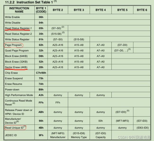
在拿到一块模块的时候,应该先写个示例程序判断模块的好坏,因此,通过读取 W25Q64 的 ID 来判断通讯情况。
#ifndef _BSP_SPI_H_
#define _BSP_SPI_H_

#include "stm32f10x.h"

#define SPI_CS_PORT                 GPIOA
#define SPI_CS_PIN                  GPIO_Pin_4

#define SPI_SCK_PORT                GPIOA
#define SPI_SCK_PIN                 GPIO_Pin_5

#define SPI_MISO_PORT               GPIOA
#define SPI_MISO_PIN                GPIO_Pin_6

#define SPI_MOSI_PORT               GPIOA
#define SPI_MOSI_PIN                GPIO_Pin_7

#define SPI_FLASH_CS_LOW()     	    GPIO_ResetBits(SPI_CS_PORT, SPI_CS_PIN )
#define SPI_FLASH_CS_HIGH()    	    GPIO_SetBits(SPI_CS_PORT, SPI_CS_PIN )

#define DUMMY            0x00
#define READ_JEDEC_ID    0x9F
#define ERASE_SECTOR     0x20
#define READ_STATUS      0x05
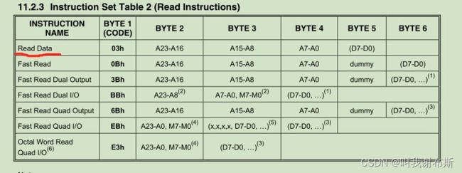
#define READ_DATA        0x03
#define WRITE_ENABLE     0x06
#define WRITE_DATA       0x02

void SPI_GPIO_Configuration(void);
uint8_t SPI_Flash_Send_Byte(uint8_t data);
uint8_t SPI_Flash_Read_Byte(void);
uint32_t SPI_Read_ID(void);
#endif
#include "bsp_spi.h"
#include "delay.h"

void SPI_GPIO_Configuration(void)
{
    GPIO_InitTypeDef GPIO_InitStructure;

    RCC_APB2PeriphClockCmd(RCC_APB2Periph_SPI1, ENABLE );
    RCC_APB2PeriphClockCmd(RCC_APB2Periph_GPIOA, ENABLE );

    //CS
    GPIO_InitStructure.GPIO_Pin = SPI_CS_PIN;
    GPIO_InitStructure.GPIO_Speed = GPIO_Speed_50MHz;
    GPIO_InitStructure.GPIO_Mode = GPIO_Mode_Out_PP;
    GPIO_Init(SPI_CS_PORT, &GPIO_InitStructure);

    //SCK
    GPIO_InitStructure.GPIO_Pin = SPI_SCK_PIN;
    GPIO_InitStructure.GPIO_Speed = GPIO_Speed_50MHz;
    GPIO_InitStructure.GPIO_Mode = GPIO_Mode_AF_PP;
    GPIO_Init(SPI_SCK_PORT, &GPIO_InitStructure);

    //MISO
    GPIO_InitStructure.GPIO_Pin = SPI_MISO_PIN;
    GPIO_InitStructure.GPIO_Speed = GPIO_Speed_50MHz;
    GPIO_InitStructure.GPIO_Mode = GPIO_Mode_IN_FLOATING;
    GPIO_Init(SPI_MISO_PORT, &GPIO_InitStructure);

    //MOSI
    GPIO_InitStructure.GPIO_Pin = SPI_MOSI_PIN;
    GPIO_InitStructure.GPIO_Speed = GPIO_Speed_50MHz;
    GPIO_InitStructure.GPIO_Mode = GPIO_Mode_AF_PP;
    GPIO_Init(SPI_MOSI_PORT, &GPIO_InitStructure);

    SPI_InitTypeDef SPI_InitStructure;
    SPI_InitStructure.SPI_Direction = SPI_Direction_2Lines_FullDuplex;
    SPI_InitStructure.SPI_Mode = SPI_Mode_Master;
    SPI_InitStructure.SPI_DataSize = SPI_DataSize_8b;
    SPI_InitStructure.SPI_CPOL = SPI_CPOL_High;
    SPI_InitStructure.SPI_CPHA = SPI_CPHA_2Edge;
    SPI_InitStructure.SPI_NSS = SPI_NSS_Soft;
    SPI_InitStructure.SPI_BaudRatePrescaler = SPI_BaudRatePrescaler_2;
    SPI_InitStructure.SPI_FirstBit = SPI_FirstBit_MSB;
    SPI_InitStructure.SPI_CRCPolynomial = 7;
    SPI_Init(SPI1, &SPI_InitStructure);

    SPI_Cmd(SPI1, ENABLE);

	SPI_FLASH_CS_HIGH();
}

void SPI_Write_Enable(void)
{
    SPI_FLASH_CS_LOW();

    SPI_Flash_Send_Byte(WRITE_ENABLE);

    SPI_FLASH_CS_HIGH();
}

uint8_t SPI_Flash_Send_Byte(uint8_t data)
{
    unsigned char retry = 0;

    while(SPI_I2S_GetFlagStatus(SPI1, SPI_I2S_FLAG_TXE) == RESET)
    {
        retry++;
        if(retry > 200)
            return 0;
    }

    SPI_I2S_SendData(SPI1, data);

    retry = 0;

    while(SPI_I2S_GetFlagStatus(SPI1, SPI_I2S_FLAG_RXNE) == RESET)
    {
        retry++;
        if(retry > 200)
            return 0;
    }

    return SPI_I2S_ReceiveData(SPI1);
}

uint8_t SPI_Flash_Read_Byte(void)
{
    return SPI_Flash_Send_Byte(DUMMY);
}

uint32_t SPI_Read_ID(void)
{
    uint32_t flash_id = 0;

    SPI_FLASH_CS_LOW();
    SPI_Flash_Send_Byte(READ_JEDEC_ID);

    flash_id = SPI_Flash_Send_Byte(DUMMY);
    flash_id <<= 8;

    flash_id |= SPI_Flash_Send_Byte(DUMMY);
    flash_id <<= 8;

    flash_id |= SPI_Flash_Send_Byte(DUMMY);
    SPI_FLASH_CS_HIGH();

    return flash_id;
}
/******************************************************************************
 **  (c)Copyright   2022
 **  ALL RIGHTS RESERVED
 **  File Name:main.c
 **  Discribe:
 **  Author  :
 **  Update List:
 **
 *******************************************************************************/

/*Includes --------------------------------------------------------------------*/

#include "main.h"
#include "delay.h"
#include "bsp_uart.h"
#include "bsp_spi.h"

TIME Time;
SYSTEM System;
STATUS Status;

int main(void)
{
    uint32_t id = 0;

    delay_init();
    USART_Config();
    SPI_GPIO_Configuration();

    printf("This is SPI_Flash Test Program\n");

    id = SPI_Read_ID();

    printf("id = %x\n", id);

    while(1)
	{

	}
}
对 W25Q64 进行数据的写入和读取
#ifndef _BSP_SPI_H_
#define _BSP_SPI_H_

#include "stm32f10x.h"

#define SPI_CS_PORT                 GPIOA
#define SPI_CS_PIN                  GPIO_Pin_4

#define SPI_SCK_PORT                GPIOA
#define SPI_SCK_PIN                 GPIO_Pin_5

#define SPI_MISO_PORT               GPIOA
#define SPI_MISO_PIN                GPIO_Pin_6

#define SPI_MOSI_PORT               GPIOA
#define SPI_MOSI_PIN                GPIO_Pin_7

#define SPI_FLASH_CS_LOW()     	    GPIO_ResetBits(SPI_CS_PORT, SPI_CS_PIN )
#define SPI_FLASH_CS_HIGH()    	    GPIO_SetBits(SPI_CS_PORT, SPI_CS_PIN )

#define DUMMY            0x00
#define READ_JEDEC_ID    0x9F
#define ERASE_SECTOR     0x20
#define READ_STATUS      0x05
#define READ_DATA        0x03
#define WRITE_ENABLE     0x06
#define WRITE_DATA       0x02

void SPI_GPIO_Configuration(void);
uint8_t SPI_Flash_Send_Byte(uint8_t data);
uint8_t SPI_Flash_Read_Byte(void);
uint32_t SPI_Read_ID(void);
void SPI_Erase_Sector(uint32_t addr);
void SPI_WaitForWriteEnd(void);
void SPI_Read_Data(uint32_t addr, uint8_t* data_buff, uint32_t data_length);
void SPI_Write_Data(uint32_t addr, uint8_t* data_buff, uint32_t data_length);

#endif
#include "stm32f10x.h"
#include "bsp_spi.h"

/**************************************************************************************************
**  函数名称:  SPI_GPIO_Configuration
**  功能描述:  SPI_GPIO初始化函数
**  输入参数:  无
**  返回参数:  无
**************************************************************************************************/
void SPI_GPIO_Configuration(void)
{
    GPIO_InitTypeDef GPIO_InitStructure;

    RCC_APB2PeriphClockCmd(RCC_APB2Periph_SPI1, ENABLE );
    RCC_APB2PeriphClockCmd(RCC_APB2Periph_GPIOA, ENABLE );

    //CS
    GPIO_InitStructure.GPIO_Pin = SPI_CS_PIN;
    GPIO_InitStructure.GPIO_Speed = GPIO_Speed_50MHz;
    GPIO_InitStructure.GPIO_Mode = GPIO_Mode_Out_PP;
    GPIO_Init(SPI_CS_PORT, &GPIO_InitStructure);

    //SCK
    GPIO_InitStructure.GPIO_Pin = SPI_SCK_PIN;
    GPIO_InitStructure.GPIO_Speed = GPIO_Speed_50MHz;
    GPIO_InitStructure.GPIO_Mode = GPIO_Mode_AF_PP;
    GPIO_Init(SPI_SCK_PORT, &GPIO_InitStructure);

    //MISO
    GPIO_InitStructure.GPIO_Pin = SPI_MISO_PIN;
    GPIO_InitStructure.GPIO_Speed = GPIO_Speed_50MHz;
    GPIO_InitStructure.GPIO_Mode = GPIO_Mode_IN_FLOATING;
    GPIO_Init(SPI_MISO_PORT, &GPIO_InitStructure);

    //MOSI
    GPIO_InitStructure.GPIO_Pin = SPI_MOSI_PIN;
    GPIO_InitStructure.GPIO_Speed = GPIO_Speed_50MHz;
    GPIO_InitStructure.GPIO_Mode = GPIO_Mode_AF_PP;
    GPIO_Init(SPI_MOSI_PORT, &GPIO_InitStructure);

    SPI_InitTypeDef SPI_InitStructure;
    SPI_InitStructure.SPI_Direction = SPI_Direction_2Lines_FullDuplex;
    SPI_InitStructure.SPI_Mode = SPI_Mode_Master;
    SPI_InitStructure.SPI_DataSize = SPI_DataSize_8b;
    SPI_InitStructure.SPI_CPOL = SPI_CPOL_High;
    SPI_InitStructure.SPI_CPHA = SPI_CPHA_2Edge;
    SPI_InitStructure.SPI_NSS = SPI_NSS_Soft;
    SPI_InitStructure.SPI_BaudRatePrescaler = SPI_BaudRatePrescaler_2;
    SPI_InitStructure.SPI_FirstBit = SPI_FirstBit_MSB;
    SPI_InitStructure.SPI_CRCPolynomial = 7;
    SPI_Init(SPI1, &SPI_InitStructure);

    SPI_Cmd(SPI1, ENABLE);

    SPI_FLASH_CS_HIGH();
}

/**************************************************************************************************
**  函数名称:  SPI_Write_Enable
**  功能描述:  写使能函数,每次往内存写数据的时候都需要先写这个函数
**  输入参数:  无
**  返回参数:  无
**************************************************************************************************/
void SPI_Write_Enable(void)
{
    SPI_FLASH_CS_LOW();

    SPI_Flash_Send_Byte(WRITE_ENABLE);

    SPI_FLASH_CS_HIGH();
}

/**************************************************************************************************
**  函数名称:  SPI_Flash_Send_Byte
**  功能描述:  写flash中写字节数据
**  输入参数:  data
**  返回参数:  uint8_t
**************************************************************************************************/
uint8_t SPI_Flash_Send_Byte(uint8_t data)
{
    unsigned char retry = 0;

    while(SPI_I2S_GetFlagStatus(SPI1, SPI_I2S_FLAG_TXE) == RESET)
    {
        retry++;
        if(retry > 200)
            return 0;
    }

    SPI_I2S_SendData(SPI1, data);

    retry = 0;

    while(SPI_I2S_GetFlagStatus(SPI1, SPI_I2S_FLAG_RXNE) == RESET)
    {
        retry++;
        if(retry > 200)
            return 0;
    }

    return SPI_I2S_ReceiveData(SPI1);
}

/**************************************************************************************************
**  函数名称:  SPI_Flash_Read_Byte
**  功能描述:  返回接收的字节数据
**  输入参数:  无
**  返回参数:  无
**************************************************************************************************/
uint8_t SPI_Flash_Read_Byte(void)
{
    return SPI_Flash_Send_Byte(DUMMY);
}

/**************************************************************************************************
**  函数名称:  SPI_Read_ID
**  功能描述:  读取设备ID
**  输入参数:  无
**  返回参数:  uint32_t
**************************************************************************************************/
uint32_t SPI_Read_ID(void)
{
    uint32_t flash_id = 0;

    SPI_FLASH_CS_LOW();
    SPI_Flash_Send_Byte(READ_JEDEC_ID);

    flash_id = SPI_Flash_Send_Byte(DUMMY);
    flash_id <<= 8;

    flash_id |= SPI_Flash_Send_Byte(DUMMY);
    flash_id <<= 8;

    flash_id |= SPI_Flash_Send_Byte(DUMMY);
    SPI_FLASH_CS_HIGH();

    return flash_id;
}

/**************************************************************************************************
**  函数名称:  SPI_Erase_Sector
**  功能描述:  擦除FLASH指定扇区
**  输入参数:  addr     24位地址值
**  返回参数:  无
**************************************************************************************************/
void SPI_Erase_Sector(uint32_t addr)
{
    SPI_Write_Enable();

    SPI_FLASH_CS_LOW();

    SPI_Flash_Send_Byte(ERASE_SECTOR);

    SPI_Flash_Send_Byte((addr >> 16) & 0xff);
    SPI_Flash_Send_Byte((addr >> 8) & 0xff);
    SPI_Flash_Send_Byte((addr) & 0xff);

    SPI_FLASH_CS_HIGH();

    SPI_WaitForWriteEnd();
}

//擦除和写入都是需要耗费时间的,因此擦除后需要等待FLASH内部时序操作完成
/**************************************************************************************************
**  函数名称:  SPI_WaitForWriteEnd
**  功能描述:  等待FLASH内部时序操作完成
**  输入参数:  无
**  返回参数:  无
**************************************************************************************************/
void SPI_WaitForWriteEnd(void)
{
    uint8_t status_reg = 0;

    SPI_FLASH_CS_LOW();

    SPI_Flash_Send_Byte(READ_STATUS);

    do
    {
        status_reg = SPI_Flash_Read_Byte();
    }while((status_reg & 0x01) == 1);

    SPI_FLASH_CS_HIGH();
}

/**************************************************************************************************
**  函数名称:  SPI_Read_Data
**  功能描述:  读取数据
**  输入参数:
**  返回参数:  无
**************************************************************************************************/
void SPI_Read_Data(uint32_t addr, uint8_t* data_buff, uint32_t data_length)
{
    SPI_FLASH_CS_LOW();

    SPI_Flash_Send_Byte(READ_DATA);

    SPI_Flash_Send_Byte((addr >> 16) & 0xff);
    SPI_Flash_Send_Byte((addr >> 8) & 0xff);
    SPI_Flash_Send_Byte((addr) & 0xff);

    while(data_length--)
    {
        *data_buff = SPI_Flash_Send_Byte(DUMMY);
        data_buff++;
    }

    SPI_FLASH_CS_HIGH();

    SPI_WaitForWriteEnd();
}

/**************************************************************************************************
**  函数名称:  SPI_Write_Data
**  功能描述:  写入数据
**  输入参数:
**  返回参数:  无
**************************************************************************************************/
void SPI_Write_Data(uint32_t addr, uint8_t* data_buff, uint32_t data_length)
{
    SPI_Write_Enable();

    SPI_FLASH_CS_LOW();

    SPI_Flash_Send_Byte(WRITE_DATA);

    SPI_Flash_Send_Byte((addr >> 16) & 0xff);
    SPI_Flash_Send_Byte((addr >> 8) & 0xff);
    SPI_Flash_Send_Byte((addr) & 0xff);

    while(data_length--)
    {
        SPI_Flash_Send_Byte(*data_buff);
        data_buff++;
    }

    SPI_FLASH_CS_HIGH();

    SPI_WaitForWriteEnd();
}
/******************************************************************************
 **  (c)Copyright   2022
 **  ALL RIGHTS RESERVED
 **  File Name:main.c
 **  Discribe:
 **  Author  :
 **  Update List:
 **
 *******************************************************************************/

/*Includes --------------------------------------------------------------------*/

#include "main.h"
#include "delay.h"
#include "bsp_uart.h"
#include "bsp_spi.h"

TIME Time;
SYSTEM System;
STATUS Status;

uint8_t write_buf[4096] = {0};
uint8_t read_buf[4096] = {0};
int main(void)
{
    uint32_t id = 0;

    delay_init();
    USART_Config();
    SPI_GPIO_Configuration();

    printf("This is SPI_Flash Test Program\n");

    id = SPI_Read_ID();

    printf("id = %x\n", id);

    SPI_Erase_Sector(0);

    SPI_WaitForWriteEnd();

    for(uint16_t i = 0; i < 4096; i++)
    {
        write_buf[i] = i;
    }

    SPI_Write_Data(0, write_buf, 4096);
    SPI_Read_Data(0, read_buf, 4096);

    for(uint16_t i = 0; i < 4096; i++)
    {
        printf("0x%x ", read_buf[i]);

        if(i % 10 == 0)
        {
            printf("\n");
        }
    }

    while(1)
	{

	}
}
