raymarching
https://blog.csdn.net/w450468524/article/details/51699086
http://iquilezles.org/www/articles/rmshadows/rmshadows.htm
https://zhuanlan.zhihu.com/p/50128840
https://zhuanlan.zhihu.com/p/34494449
https://zhuanlan.zhihu.com/p/90245545 https://github.com/MashiroShina/RayMarchingPlayBall 代码
https://cowlevel.net/article/2036247
https://blog.csdn.net/tjw02241035621611/article/details/80057928 有源码
https://blog.csdn.net/u013477973/article/details/85317717
https://flafla2.github.io/2016/10/01/raymarching.html
https://9bitscience.blogspot.com/2013/07/raymarching-distance-fields_14.html
最近研究云的渲染接触到了体绘制,在shadertoy上看了一些例子,不过它们都是全场景体绘制的,场景中的所有物体,地形均由数学方法生成。然后用一个quad覆盖整个屏幕,对每个片段进行raymarching,甚至是raytracing。好像有一个64kb的比赛,就是用最小的程序大小,看谁能够渲染出最漂亮的图像,令人不得不感叹数学的神奇。
要想系统的了解体绘制,推荐有一本非常好的书,Real-Time Volume Graphics,里面不仅介绍了用于科学领域的体绘制,而且针对游戏开者,非常详细的讲述了如何在GPU上实现并优化,如何将体绘制与传统的基于几何面片的渲染方式集成起来。
raymarching 算法
raymarching 算法思想很直观:首先有一个3D的体纹理,然后从相机发射n条射线,射线有一个采样的步长。当射线处在体纹理中时,每个步长采一次样,获取纹理值(实际上表示该店的密度值),计算光照,然后和该条射线当前累积的颜色值进行混合。
确定raymarching片段
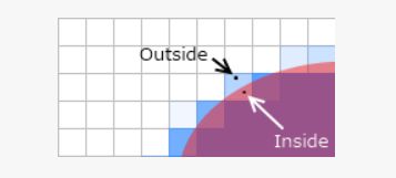
体绘制首先需要一个载体(proxy geometry),也就是为了确定屏幕上的哪些像素是属于某个体纹理的。这个问题很容易就让人联想到包围盒,问题也就迎刃而解。
我们只需要将体纹理的包围盒绘制出来,那么包围盒在屏幕上覆盖的片段自然就是需要进行raymarching的了。如图所示:
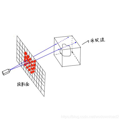
随后只需要执行raymarching的片段着色器即可。
https://www.jianshu.com/p/46e161b911dd
raymarching是什么?
假定大家对光线跟踪(ray tracing)都十分熟悉,那么ray marching可以看做ray tracing的一种实现,主要针对“光线与物体求交”这一步,每次让光线前进一定步长,并检测当前光线是否位于物体表面,据此调整光线前进幅度,直到抵达物体表面,再按照一般光线追踪的方法计算颜色值。
为什么要用Ray Marching
乍看起来ray marching好像比主流的ray tracing实现粗暴多了,光线不知道得走多少步才能碰到物体表面,效率应该比主流ray tracing低不少的样子。鉴于目前光线跟踪效率并不高(不过在不久的未来还是有希望应用在高质量游戏渲染上的)。
distance field
为实现ray marching,我们需要引入距离场(distance field)这一重要概念。距离场是三维空间中一个标量场,任意一点的数值代表离该点最近的模型表面的点的距离下界。通过距离场可以很方便地估计光线应当前进的幅度:只需让光线前进当前距离场大小的数值即可,即所谓sphere tracing。
RayMarching的原理如下:
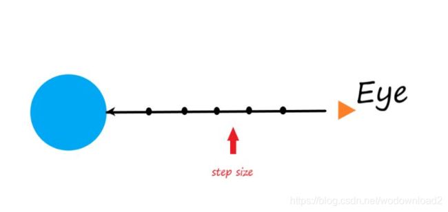
从观察点发射一条射线,顺着这条射线每次延伸一段固定距离,判断是否碰撞到物体。通常延伸的步数是有限的,并且延伸的单步距离太大会导致穿透很薄的物体。那么有了射线,我们如何去跟物体做碰撞检测呢?一般来说我们会使用SDF(signed distance function)。例子:
float4 hitCol = float4(0,0,0,0);
for(int currStep = 0; currStep < steps; currStep++)
{
	if(distance(currPos, objCenter) < radius)
	{
		return float4(0,1,0,1); //返回绿色
	}
	else
	{
		currPos -= direction * stepSize;
	}
}
return hitCol;
上面代码中的:
distance(currPos, objCenter) < radius
其实就是一个distance function,用来定义一个球体。目前这个渲染结果看起来一般,下面加入lambert光照。

CL是颜色;
N是法线;
IL是入射光方向;
写的什么烂博客。
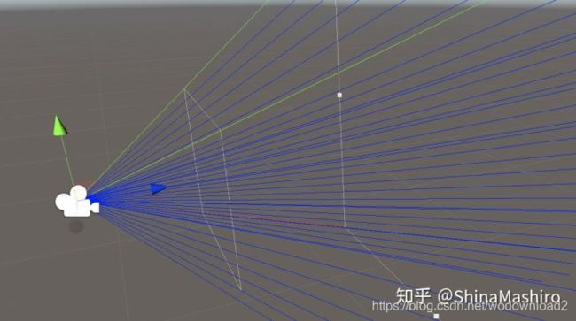
初始化相机
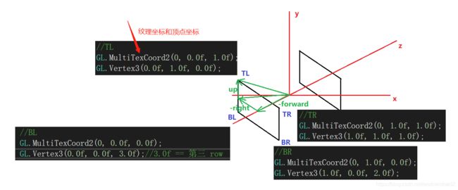
我们首先需要初始化相机的视锥方便我们在shader中来得到光线的方向。
相机我们设置好后,当然是要在shader中获得我们刚刚设置的四个的顶点。这里我们通过vertex着色器指定顶点后,通过frag着色器的差值来获得每一根射线的方向。
伪代码
  v2f vert (appdata v)
            {
                ...
                o.ray=_CamFrustum[(int)index].xyz;
                o.ray/=abs(o.ray.z);//z=-1
                o.ray=mul(_CamToWorld,o.ray);

                return o;
            }
            fixed4 frag (v2f i) : SV_Target
            {
		Ray ray=createRay(_WorldSpaceCameraPos,normalize(i.ray.xyz));
                return ray.direction;
            }
raymarching算法的实现分析:
v2f vert (appdata v)
{
    v2f o;
    half index = v.vertex.z;
    v.vertex.z = 0;
    o.vertex = UnityObjectToClipPos(v.vertex);
    o.uv = v.uv;

    o.ray=_CamFrustum[(int)index].xyz;
    o.ray/=abs(o.ray.z);//z=-1
    o.ray=mul(_CamToWorld,o.ray);
    return o;
}
看看如何计算射线。
_raymarchMaterial.SetMatrix("_CamFrustum", CamFrustum(_camera));
private Matrix4x4 CamFrustum(Camera cam)
{
	Matrix4x4 frustum = Matrix4x4.identity;
	float fov = Mathf.Tan(cam.fieldOfView * 0.5f * Mathf.Deg2Rad);
}
Camera.fieldOfView
description
the filed of view of the camera in degrees.
this is the vertical of view; horizontal field of view varies depending on the viewport’s aspect ratio.
https://docs.unity3d.com/ScriptReference/Camera-fieldOfView.html
Vector3 goUp = Vector3.up * fov;
Vector3 goRight = Vector3.right * fov * cam.aspect;
这个参考:https://cowlevel.net/article/2036247
o.ray=_CamFrustum[(int)index].xyz;
o.ray/=abs(o.ray.z);//z=-1
o.ray=mul(_CamToWorld,o.ray);
矩阵选择方向的视频:https://www.youtube.com/watch?v=8XRvpDhTJpw
v2f vert (appdata v)
{
    v2f o;
    half index = v.vertex.z;
    v.vertex.z=0;
    o.vertex = UnityObjectToClipPos(v.vertex);
    o.uv = v.uv;

    o.ray=_CamFrustum[(int)index].xyz;
    o.ray/=abs(o.ray.z);//z=-1
    o.ray=mul(_CamToWorld,o.ray); //方向变为世界的方向

    return o;
}
测试代码:
using System.Collections;
using System.Collections.Generic;
using UnityEngine;
[ExecuteInEditMode]
public class NewBehaviourScript : MonoBehaviour
{
public Camera camera;
public GameObject cube;
public GameObject dir;
void OnDrawGizmos()
{
DrawWorldAxis();
DrawCameraAxis();
}
void DrawWorldAxis()
{
Gizmos.color = Color.blue;
Gizmos.DrawLine(Vector3.zero, Vector3.zero + Vector3.forward * 5); //z方向
Gizmos.color = Color.red;
Gizmos.DrawLine(Vector3.zero, Vector3.zero + Vector3.right * 5); //x方向
Gizmos.color = Color.green;
Gizmos.DrawLine(Vector3.zero, Vector3.zero + Vector3.up * 5); //y方向
}
void DrawCameraAxis()
{
Vector3 camPos = camera.transform.position;
Gizmos.color = Color.blue;
Gizmos.DrawLine(camPos, camPos + camera.transform.forward * 5); //z方向
Gizmos.color = Color.red;
Gizmos.DrawLine(camPos, camPos + camera.transform.right * 5); //x方向
Gizmos.color = Color.green;
Gizmos.DrawLine(camPos, camPos + camera.transform.up * 5); //y方向
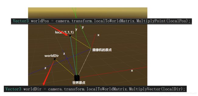
Vector3 localPos = new Vector3(1, 1, 1);
Gizmos.color = Color.yellow;
Vector3 worldPos = camera.transform.localToWorldMatrix.MultiplyPoint(localPos);
cube.transform.position = worldPos;
Gizmos.DrawLine(camPos, worldPos);
Gizmos.color = Color.cyan;
Gizmos.DrawLine(Vector3.zero, worldPos);
Gizmos.color = Color.white;
Gizmos.DrawLine(Vector3.zero, camPos);
Vector3 localDir = new Vector3(1, 1, 1);
Gizmos.color = Color.yellow;
Vector3 worldDir = camera.transform.localToWorldMatrix.MultiplyVector(localDir);
Gizmos.DrawLine(Vector3.zero, worldDir);
dir.transform.position = worldDir;
}
}
https://docs.unity3d.com/ScriptReference/Camera-cameraToWorldMatrix.html
这个和camera.transform.localToWorldMatrix不同。

fixed4 frag (v2f i) : SV_Target
{
    float depth = LinearEyeDepth(tex2D(_CameraDepthTexture,i.uv).r);
采样得到实际的深度。
depth *= length(i.ray.xyz);
使用差值之后的射线的长度缩放深度。
fixed3 col = tex2D(_MainTex,i.uv);
采样后处理的纹理。
Ray ray=createRay(_WorldSpaceCameraPos,normalize(i.ray.xyz));
创建射线:
Ray createRay(float3 origin,float3 direction)
{
	Ray ray;
	ray.origin=origin;
	ray.direction=direction;
	return ray;
}
origin是摄像机的世界坐标,即原点位置。direction为摄像机发出的射线。
即每条射线的原点都是摄像机,朝向不同而已。
RayHit hit;
fixed4 result;
hit = raymarching( ray,depth,_MaxIterations,_maxDistance,1);
射线击中的点:
struct RayHit
{
	float4 position;
	float3 normal;
	float3 color;
};
RayHit raymarching(Ray ray,float depth,int MaxIterations,int maxDistance,int atten)
{
	RayHit bestHit = CreateRayHit();
创建一个击中的点:
RayHit CreateRayHit()
{
	RayHit hit;
	hit.position = float4(0.0f, 0.0f, 0.0f,0.0f);
	hit.normal = float3(0.0f, 0.0f, 0.0f);
	hit.color = float3(0.0f, 0.0f, 0.0f);
	return hit;
}
这既是初始化一个击中的点。
float t=0;
for(int i=0;i<MaxIterations;i++)
{
遍历MaxIterations次数。
if(t>maxDistance||t>=depth)
{
	bestHit.position = float4(0,0,0,0);
    break;
}
如果不行的距离累加值,大于maxDistance或者是t>=depth则进行break。
说明光线行进了太多啦啦啦啦,不能再继续步进。
float3 p = ray.origin + ray.direction*t;
float4 d = distenceField(p);
射线的原点即摄像机的位置,加上t的缩放ray.direction,第一次t=0
float4 distenceField(float3 p)
{
	float4 combines;
	float4 combines;
	combines=float4(_sphereColor.rgb, sdSphere(p-_spheres[0].xyz,_spheres[0].w));
	//_spheres[0]第0个球,xyz位置,w为半径
距离场。
sdSphere
#include “DistanceFunctions.cginc”
// Sphere
// s: radius
float sdSphere(float3 p, float s)
{
	return length(p) - s;
}
点p,距离圆心的距离。
关于本篇博客的代码的注释:https://flafla2.github.io/2016/10/01/raymarching.html
interacting with mesh-based objects
so now u have constructed a bounch of objects using distance fields and u are ready to intergrate them into you unity project. however, u run into a major problem very quickly: mesh-based objects and raymarched objects can not interact with or touch each other! in fact, the raymarched objects always float on top of everything else, because our raymarcher does not take depth into account. the video below illustrates this:
https://flafla2.github.io/gfycat_old/GrossThoroughEasternnewt.mp4
to fix this problem, we need to find the distance along each ray at which the closest mesh-based object lies. If our raymarch loop marches past this point, we bail out and render that object instead (because it is in front of any potential raymarched objects).
to find this distance, we need to take advantage of the depth buffer. the depth buffer is accessible to all image effects shaders and stores the eyespace depth of the closest object in the scene for each pixel. refer to figure 5 below for more context.
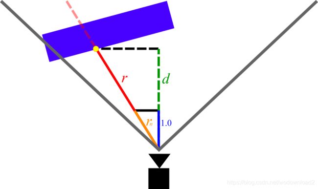
Figure 5: Diagram of the measurements we are interested in when calculating depth. The red line is the ray for some arbitrary pixel.
In Figure 5, the magnitude of r is the measurement that we are trying to find (depth beyond which we should bail out in the raymarch loop). The magnitude of d is the eyespace depth that is given to us for that pixel by the depth buffer (note that d is shorter than r, because d does not account for perspective).
In order to find the magnitude of r we can simply leverage the rules of similar triangles. Consider rn, the vector with the same direction as r but with length 1.0 in the z direction. We can write rn as:
![]()
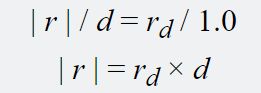
In the above equation, rd is the vector with the same direction as r but with an arbitrary length (in other words, the ray vector that our shader is given). Clearly, from Figure 5 r and rn create two similar triangles. By multiplying rn by d (which we know from the depth buffer) we can derive r and its magnitude as follows:
Using the depth buffer in our shader
Now we need to make some modifications to our code to align with the above theory. First, we need to make some changes to our vertex shader so that it returns rn instead of rd:
v2f vert (appdata v)
{
    // ...

    // Dividing by z "normalizes" it in the z axis
    // Therefore multiplying the ray by some number i gives the viewspace position
    // of the point on the ray with [viewspace z]=i
    o.ray /= abs(o.ray.z);

    // Transform the ray from eyespace to worldspace
    o.ray = mul(_CameraInvViewMatrix, o.ray);

    return o;
}
Note that we are dividing by abs(o.ray.z) instead of simply o.ray.z. This is because in eyespace coordinates, z < 0 corresponds to the forward direction. If we were to divide by a negative number, the ray direction would flip when dividing (and therefore the entire raymarched scene would appear flipped).
the final step is to integrate depth into our fragment shader and raymarch loop:
// Raymarch along given ray
// ro: ray origin
// rd: ray direction
// s: unity depth buffer
fixed4 raymarch(float3 ro, float3 rd, float s) {
    fixed4 ret = fixed4(0,0,0,0);

    const int maxstep = 64;
    float t = 0; // current distance traveled along ray
    for (int i = 0; i < maxstep; ++i) {
        // If we run past the depth buffer, stop and return nothing (transparent pixel)
        // this way raymarched objects and traditional meshes can coexist.
        if (t >= s) {
            ret = fixed4(0, 0, 0, 0);
            break;
        }

        // ...
    }

    return ret;
}

// ...
uniform sampler2D _CameraDepthTexture;
// ...

fixed4 frag (v2f i) : SV_Target
{
    // ray direction
    float3 rd = normalize(i.ray.xyz);
    // ray origin (camera position)
    float3 ro = _CameraWS;

    float2 duv = i.uv;
    #if UNITY_UV_STARTS_AT_TOP
    if (_MainTex_TexelSize.y < 0)
        duv.y = 1 - duv.y;
    #endif

    // Convert from depth buffer (eye space) to true distance from camera
    // This is done by multiplying the eyespace depth by the length of the "z-normalized"
    // ray (see vert()).  Think of similar triangles: the view-space z-distance between a point
    // and the camera is proportional to the absolute distance.
	//line 45
    float depth = LinearEyeDepth(tex2D(_CameraDepthTexture, duv).r);
    depth *= length(i.ray.xyz);

    fixed3 col = tex2D(_MainTex,i.uv);
    fixed4 add = raymarch(ro, rd, depth);

    // Returns final color using alpha blending
    return fixed4(col*(1.0 - add.w) + add.xyz * add.w,1.0);
}
on line 45, we access unity’s depth texture using the standard unity shader uniform _CameraDepthTexture, and convert it to eyespace depth using LinearEyeDepth(). Next, on line 46, we multiply the depth by the length of rn, which was passed to us by the vertex shader, satisfying the equations discussed above.
继续回到函数:
float4 distenceField(float3 p)
{
	float4 combines;
	combines=float4(_sphereColor.rgb, sdSphere(p-_spheres[0].xyz,_spheres[0].w));
	for(int i=1; i<_sphereNum; i++)
	{
	    float4 sphereAdd=float4(_sphereColor.rgb, sdSphere(p-_spheres[i].xyz,_spheres[i].w));
	    combines = opUS(combines,sphereAdd,_sphereSmooth);//opUS
	}
	float4 sphere=float4(_sphereColor.rgb, sdSphere(p-_sphereRigi[0].xyz,_sphereRigi[0].w));
	for(int i=1; i<_sphereRigiNum; i++)
	{
	    float4 sphereAdd2=float4(_sphereColor.rgb, sdSphere(p-_sphereRigi[i].xyz,_sphereRigi[i].w));
	    sphere = opUS(sphere,sphereAdd2,_sphereSmooth);//opUS
	}
	combines = opUS(combines,sphere,_sphereSmooth);//opUS
	combines=opUS(combines,float4(_GroundColor.rgb,sdPlane(p,float4(0,1,0,0))),_sphereSmooth);
	return combines;
}
这段函数主要是为了造型。
combines的前三维表示rgb颜色,w表示距离。
float4 d = distenceField(p);
if(d.w < _Accuracy)
{
	bestHit.position = float4(p,1);
	bestHit.normal = getNormal(p);
	bestHit.color = d.rgb/atten;
    break;
}
t+=d.w;
}
如果距离小于精度_Accuracy,则进行点的计算,然后break。否则继续步进。t+=d.w;前进了d.w的距离。
bestHit.position = float4(p,1); //得到点的位置
bestHit.normal = getNormal§; //得到该点的法线
bestHit.color = d.rgb/atten; //颜色除以衰减值
继续片段着色器:
RayHit hit;
hit = raymarching( ray,depth,_MaxIterations,_maxDistance,1);
if(hit.position.w==1)
{
    float3 s=Shading(ray,hit,col);//setcolor
如果hit.position.w==1表示点,则进行着色。
Shading函数:
float3 Shading(inout Ray ray,RayHit hit,float3 col)
{
    float3 light =(_LightCol* dot(-_LightDir,hit.normal) * 0.5+0.5)*_LightIntensity;
三个参数:射线、击中的点、颜色
fixed3 col = tex2D(_MainTex,i.uv)
float3 s=Shading(ray,hit,col);//setcolor
_LightCol-》灯光的颜色
_LightDir-》灯光的方向
hit.normal-》当前点的法线
lambert模型。
继续:
float shadow=softShadow(hit.position.xyz,-_LightDir,0.1,_ShadowDistance.y,_ShadowPenumbra)*0.5+0.5;
softShadow,加入软阴影
hit.position.xyz-》点的位置
-_LightDir-》光源的-forward方向
0.1-》影子的最小偏移距离
_ShadowDistance.y-》外部传入,使用y值,影子偏移的最大位置
_ShadowPenumbra-》本影区
softShadow返回的是一个系数
shadow = max(0.0,pow(shadow,_ShadowIntensity)); //对系数进行pow处理
return float3(hit.colorlightshadTransparent(ray,hit,col))shadowao;
最后返回的是点颜色、灯光颜色、透明度、影子系数、ao系数,相乘的结果。
完整的阴影:
float softShadow(float3 ro,float3 rd,float mint,float maxt,float k)
{
    float result=1.0;
    for(float t=mint; t<maxt;)
    {
        float h=distenceField(ro+rd*t).w;
        if(h<0.001)
        {
            return 0.0;
        }
        result = min(result,k*h/t);
        t+=h;
    }
    return result;
}
从交点,沿着灯光方向,行进,最大走到maxt。
最后加入影子、光照、ao、环境反射,最终得到一个颜色并且返回。
以下是:
https://9bitscience.blogspot.com/2013/07/raymarching-distance-fields_14.html
introduction:
raymarching is a 3d-rendering technique, praised by programming-enthusiasts 编程爱好者 for both its simplicity and speed. it has been used extensively in the demoscene, producing low-size executables and amazing visuals.
the most frontstanding figure behind its popularity, is Inigo Quilez, http://iquilezles.org/
promoting it with his presentation at nvscene: rendering worlds with two triangles.
the idea is this: say u have some surface in space. u do not have an explicit formular for it, nor a set of triangles describing it. but u can find out how far away it is, from any point. how would u render this surface?
first of all, we need to find out which points that lie on the surface, and what pixels they correspond to. to do this we use a technique known as ray-casting.
imagine u and your monitor being placed in this virtual world. your eye will be looking at a rectangle (your monitor), which we shall call the image plane. ray-casting works by shooting rays from the eye through each pixel on the image plane, and fiinding the closest object blocking the path of the ray. once we hit an object, we can compute the color and shading of the corresponding pixel. if the ray does not hit anything, the pixel is colored with some sky color.
there are several ways in which we can calculate the intersection, for example we analytically solve for it. a raymarcher, however, looks for an approximate solution, by marhcing along the ray in steps until it finds an intersection. by controlling the step size using a distance field, we can reach blazing speeds, even on a regular laptop GPU.
the raymarching algorithm
in traditional raytracing, a scene is often described by a set of triangles or spheres, making up a mesh. using some spatial acceleration structure, we can quickly solve for the exact intersections between the rays and the objects.
with raymarhcing however, we allow for some leeway in the intersection, and accept it when a ray is close enough to a surface. this is done by marching along the ray at step sizes, and checking whether or not the surface is within a given threshold. we can set a limit on the number of steps to prevent marching into oblivion 遗忘. in code the algorithm looks like this:
bool raymarch(vec3 rayOrigin, vec3 rayDirection)
{
    float t = 0.0f;
    for(int i = 0; i < maxSteps; ++i) {
        float d = sceneDistance(rayOrigin + rayDirection * t);
        if(d < epsilon) {
            // Do something with p
            return true;
        }
        t += d;
    }
    return false;
}
but this can be slow if the step size is small, and inaccurate if the step size is large. so we speed things by implementing a variable step size, and that is where distance fileds comes in.
the basic idea is to make sure every surface in our scene is given by a distance estimator (DE). which returns the distance to it from a point p. this way, we can find the distance to the cloest surface in the scene, and know that we can step this far without overshooting.

distance estimators
consider a sphere centered at the origin with radius r. the distance from a point p to the sphere is given by:
float distSphere(vec3 p, float radius) {
    return length(p) - radius;
}
this function gives us signed distance, because the distance is negative or positive depending on whether we are inside or outside the sphere. in the later sections we will see that this is important in order to compute the surface normal.
coming up with your own DE’s can be difficult, so feel free to take a look at this page, http://www.iquilezles.org/www/articles/distfunctions/distfunctions.htm
by Inigo Quilez, for a list of distance functions. a useful trick though is to take advantage of symmetry. for example, a box at the origin can be split into the 8 octans, 象限 but we do not need to handle each region on its own. instead we can take the absolute value of the point, and then compute the distance.
the distance field
once we have the distance to each surface, the scene can be described by a function returning the minimum of them, i.e.:
float distanceField(vec3 p)
{
    float d1 = sphere_of_radius_one(p)
    float d2 = box_one_unit_to_left(p)
    return min(d1, d2);
}
We expect that this function provides us a lower-bound on the closest object. It is therefore important that the distance estimators do not under-estimate the distance, as we might risk overshooting.
Various operations can be performed on the distance fields. For example, the union of two distance fields is the minimum, the intersection is maximum, and the complement is the negated distance (assuming it is signed). This is described in more detail at the above mentioned page.
a simple scene
it is time to put the theory to the test. but how do we go from pixels in the image, to points in our virtual world?
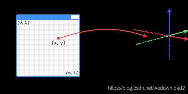
let us say that our window has a position and orientation in the world, the image plane. for the sake of simplicity, we scale it down to a rectangle of width and height 2 units. we define a pair of coordinates, u and v, both going from -1 to 1, representating the corners of the rectangle. this way, the top-left corner of the window (0,0), becomes (-1,1) in uv coordinates. while the bottom-right corner becomes (1,-1).
we decide the orientation of the rectangle by defining an up-vector and a right-vector. a point on the image plane in world-coordinate is then:
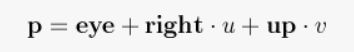
for this scene, let us say we fire rays perpendicular out of the image plane. if our up-vector is along the y-axis, the right-vector is along the x-axis, the forward-vector is either down the positive or negative z-axis. the former 向前向量 can be found by crossing the right vector with the up vector.
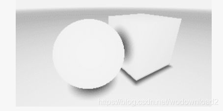
our scene is now everything from -1 to 1 on the x- and y-axis, looking down the positive z-axis. we position the eye at [0,0,-1], and have a single distance function: a sphere of radius 0.5. if the raymarch function hits the sphere, we color the pixel white, else we color it black. the code for this fits nicely in a shader.
void main()
{
    vec3 eye = vec3(0, 0, -1);
    vec3 up = vec3(0, 1, 0);
    vec3 right = vec3(1, 0, 0);

    float u = gl_FragCoord.x * 2.0 / g_resolution.x - 1.0;
    float v = gl_FragCoord.y * 2.0 / g_resolution.y - 1.0;
    vec3 ro = right * u + up * v;
    vec3 rd = normalize(cross(right, up));

    vec4 color = vec4(0.0); // Sky color

    float t = 0.0;
    const int maxSteps = 32;
    for(int i = 0; i < maxSteps; ++i)
    {
        vec3 p = ro + rd * t;
        float d = length(p) - 0.5; // Distance to sphere of radius 0.5
        if(d < g_rmEpsilon)
        {
            color = vec4(1.0); // Sphere color
            break;
        }

        t += d;
    }

    return color;
}
i believe it is much more exciting if u do this yourself, so i will let u render this on your own.
perspective
notice that in the first example, the ray direction was equal to the forward vector, causing every ray to be cast perpendicular to the image plane. this is actually how orthographic projection works, and is not very three-dee-y. what we want, is an illusion of depth. to do this, we can simulate a pinhole camera by positioning the eye behind the image plane, like so:
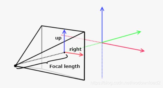
the distance between the eye and the image plane is analogue to the focal length of a camera lens and focal point. the best part is, this does not change the behaviour of the rays, but merely what direction we cast them!
a point on the image plane is now given by:
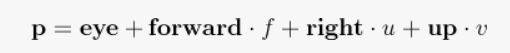
where f is the distance between the eye and the image plane, along the forward vector.
the ray direction can now be found by taking the difference between the image plane position and the eye.
Rendering techniques
A simple black or white image is not too exciting. Alot of these can be found both in the presentation mentioned in the introduction, and various pages in this thread.
iteration count
a quick way to spice things up, is to let the color depend on the ray step count. that is, how many steps the raymarch function performed before bailing out or hitting a surface. this will allow u to see where the most intensive portions of your image are.

iteration-based coloring. the maximum step count was set to 64.
bounding volume
we can speed up the raymarching if we limit the rays to a certain bounding volume.
remember that in the raymarching function we repeatedly calcualte the distance to the closest surface, and travel along the ray direction by this amount. the sum of the distances will be how far the ray has traveled so far. using this, we can drop a ray as soon as it is further away than some limit.
fog
fog is important to get a sense of scale and distance, and can be used to avoid artifacts in the distance.
to get fog, we can simply blend the distance from the eye with the skin color. in the simplest case, we can define the near-and far-cliping planes to have blending factors of 0 and 1, respectively, and linearly interpolate between these based on the distance.
more realistic blending methods can be found here.
http://www.iquilezles.org/www/articles/fog/fog.htm
anti-aliasing
instead of casting a single ray per pixel, we can distribute multiple rays inside a single pixel, sum the results and calculate the average. this will effectively remove sharp edges, and wreck 沉、下降your framerate at the same time, so be careful.
an interesting optimization could be to only perform AA if the iteration count is above the average, 只在那些迭代次数超过平均值的才去执行AA, as it likely indicates the edge of an object. 因为很大的可能是在边上,以为只有边才会有锯齿。
Lighting
A simple lighting model is the Lambertian reflectance model. The idea is that the light intensity at a point depends on the angle between the surface normal and the direction to the light. By clamping the dot product of these vectors between 0 and 1, we get a measure for how strongly the point should be lit. For more on lighting models, Arcsynthesis’ tutorial explains the topic quite well: Arcsynthesis: Lights on.
We need to compute the surface normal. Our distance function is special type of function known as a scalar field, because it assigns each point (x, y, z) a scalar quantity (the distance to the closest surface). Knowing this, we can approximate the surface normal using what is known as the gradient.
The gradient of a scalar field is a vector, pointing in the direction where the field increases or decreases the most. Its magnitude is how big this change is. Naturally, the distance to a surface will increase more if we move normally away from it, rather than parallell to it. Thus, the gradient points in the same direction as the normal.
The gradient can be approximated by numerical differentation, and normalized to give us the surface normal. The lighting of the point can now be computed. For example:
vec4 shade(vec3 p)
{
    vec3 normal = getNormal(p);
    vec3 lightDir = normalize(lightPosition - p);
    float LightIntensity = lightColor * dot(normal, lightDir);
    return getReflectance(p) * lightIntensity;
}
Shadows
Light rarely looks good without shadows. Luckily for us, this is fairly easy to implement. Simply check if the path from the point to shade to each light source is obstructed or not, by raymarching. This will produce a hard-shadow, but it is possible to get good looking soft-shadows, almost for free.
http://www.iquilezles.org/www/articles/rmshadows/rmshadows.htm
Ambient occlusion
Once we have obtained the surface normal (see the section about Lighting), we can easily fake an ambient occlusion effect. A proposed method is to sample along the surface normal a couple of times, comparing the value of the distance field with the actual distance from the surface. For example, if the difference is 0, the surface is not occluded. If there are other surfaces closer to the ray at the sample point, the difference will be non-zero.