【Verilog】HDLBits刷题 03 Verilog语言(2)(未完)
二、模块(module)
1. 实例化
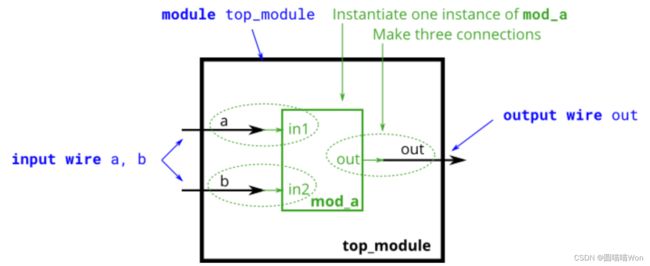
The figure below shows a very simple circuit with a sub-module. In this exercise, create one instance of module mod_a, then connect the module's three pins (in1, in2, and out) to your top-level module's three ports (wires a, b, and out). The module mod_a is provided for you — you must instantiate it.
(下图显示了一个带有子模块的非常简单的电路。在本练习中,创建模块 mod_a 的一个实例,然后将该模块的三个引脚(in1、in2 和 out)连接到顶级模块的三个端口(电线 a、b 和 out)。模块 mod_a 是为您提供的 - 您必须实例化它。)
module top_module (
	input a,
	input b,
	output out
);

	// Create an instance of "mod_a" named "inst1", and connect ports by name:
	mod_a inst1 (
		.in1(a), 	// Port"in1"connects to wire "a"
		.in2(b),	// Port "in2" connects to wire "b"
		.out(out)	// Port "out" connects to wire "out"
				// (Note: mod_a's port "out" is not related to top_module's wire "out".
				// It is simply coincidence that they have the same name)
	);

/*
	// Create an instance of "mod_a" named "inst2", and connect ports by position:
	mod_a inst2 ( a, b, out );	// The three wires are connected to ports in1, in2, and out, respectively.
*/

endmodule
2.
3.
4. 多模块实例化
You are given a module my_dff with two inputs and one output (that implements a D flip-flop). Instantiate three of them, then chain them together to make a shift register of length 3. The clk port needs to be connected to all instances.
The module provided to you is: module my_dff ( input clk, input d, output q );
Note that to make the internal connections, you will need to declare some wires. Be careful about naming your wires and module instances: the names must be unique.
(给您一个模块 my_dff,它具有两个输入和一个输出(实现 D 触发器)。实例化其中三个,然后将它们链接在一起以形成长度为 3 的移位寄存器。clk 端口需要连接到所有实例。
提供给您的模块是: module my_dff ( 输入 clk, 输入 d, 输出 q );
请注意,要进行内部连接,您将需要声明一些电线。命名电线和模块实例时要小心:名称必须是唯一的。)
module top_module (
	input clk,
	input d,
	output q
);

	wire a, b;	// Create two wires. I called them a and b.

	// Create three instances of my_dff, with three different instance names (d1, d2, and d3).
	// Connect ports by position: ( input clk, input d, output q)
	my_dff d1 ( clk, d, a );
	my_dff d2 ( clk, a, b );
	my_dff d3 ( clk, b, q );

endmodule
5.
You are given a module my_dff8 with two inputs and one output (that implements a set of 8 D flip-flops). Instantiate three of them, then chain them together to make a 8-bit wide shift register of length 3. In addition, create a 4-to-1 multiplexer (not provided) that chooses what to output depending on sel[1:0]: The value at the input d, after the first, after the second, or after the third D flip-flop. (Essentially, sel selects how many cycles to delay the input, from zero to three clock cycles.)
The module provided to you is: module my_dff8 ( input clk, input [7:0] d, output [7:0] q );
The multiplexer is not provided. One possible way to write one is inside an always block with a case statement inside. (See also: mux9to1v)
(给您一个模块 my_dff8,它有两个输入和一个输出(实现一组 8 个 D 触发器)。实例化其中三个,然后将它们链接在一起以形成长度为 3 的 8 位宽移位寄存器。此外,创建一个 4 比 1 多路复用器(未提供),根据 sel[1:0] 选择输出内容:第一个、第二个或第三个 D 触发器之后的输入 d 处的值。 (本质上,sel 选择延迟输入的周期数,从零到三个时钟周期。)
提供给您的模块是: module my_dff8 ( 输入 clk, 输入 [7:0] d, 输出 [7:0] q );
未提供多路复用器。一种可能的编写方法是在一个带有 case 语句的always块中。 (另请参阅:mux9to1v))
【连载中】


