使用LLM自动化生成微电网Simulink模型
使用LLM自动化生成微电网Simulink模型!⚡
在构建微电网仿真模型时,我们通常需要手动拖拽模块、设置参数,耗费大量时间。现在,通过结合LLM(如 GPT-4)与 MATLAB 脚本,我们可以自动生成完整的微电网 Simulink 模型!
微电网模型核心功能:
- 光伏功率生成:通过正弦波模拟白天和夜晚光伏输出的动态变化。
- 电池管理系统(BMS):基于净功率实现电池的充放电控制,动态更新 SOC(电池状态)。
- ⚡ 负载建模:叠加固定负载和随机波动,模拟实际用电需求。
- SOC 显示:实时监控电池状态变化。
使用GPT-4o
prompt是:微电网 Simulink 模型代码 自动生成,然后后面根据error在调整了几个prompt(不展示,私聊)
自动化生成过程
-
设计核心模块:
使用 MATLAB 脚本调用 Simulink API,自动生成光伏、负载、净功率计算、电池控制等模块,并用代码连接它们。 -
MATLAB Function 模块:
- 将电池控制逻辑写成独立的 MATLAB 函数(如
battery_control.m)。 - 在 Simulink 模型中用 MATLAB Function 模块调用该函数。
- 将电池控制逻辑写成独立的 MATLAB 函数(如
-
调试与优化:
- 修复常见错误,如端口连接问题、模块配置错误等。
- 确保所有模块的输入/输出逻辑清晰且正确。
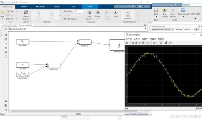
效果展示
通过脚本运行后,生成以下微电网 Simulink 模型:
- 光伏功率通过正弦波模块动态变化。
- 负载功率由常量模块和随机波动模块叠加生成。
- 电池控制模块实时管理 SOC,确保电池工作在安全范围内。
- 所有数据通过 Scope 模块实时显示。
️ 示例代码
以下是核心自动化脚本的部分内容:
% 自动生成微电网 Simulink 模型
clc;
clear;

% 创建新模型
model_name = 'MicrogridModel';
new_system(model_name); % 新建 Simulink 模型
open_system(model_name); % 打开模型

% 设置模型基础参数
sim_time = '24'; % 仿真时间设为 24 秒
set_param(model_name, 'StopTime', sim_time);

% 定义模块位置参数
x0 = 50; y0 = 50; x_step = 200; y_step = 150;

%% 添加模块到模型
% 光伏功率模块 (Sine Wave)
add_block('simulink/Sources/Sine Wave', [model_name, '/PV Power'], ...
    'Position', [x0, y0, x0 + 80, y0 + 30], ...
    'Amplitude', '100', 'Frequency', '2*pi/24', 'Phase', '0');

% 负载功率模块 (Constant + Random)
add_block('simulink/Sources/Constant', [model_name, '/Load Base'], ...
    'Position', [x0, y0 + y_step, x0 + 80, y0 + y_step + 30], ...
    'Value', '50');
add_block('simulink/Sources/Random Number', [model_name, '/Load Variation'], ...
    'Position', [x0, y0 + y_step + 60, x0 + 80, y0 + y_step + 90], ...
    'Mean', '0', 'Variance', '20');
add_block('simulink/Math Operations/Add', [model_name, '/Load Power'], ...
    'Position', [x0 + x_step, y0 + y_step, x0 + x_step + 80, y0 + y_step + 30]);

% 净功率计算模块 (Add)
add_block('simulink/Math Operations/Add', [model_name, '/Net Power'], ...
    'Position', [x0 + 2*x_step, y0, x0 + 2*x_step + 80, y0 + 30]);

% 电池控制模块 (MATLAB Function)
add_block('simulink/User-Defined Functions/MATLAB Function', [model_name, '/Battery Control'], ...
    'Position', [x0 + 3*x_step, y0, x0 + 3*x_step + 120, y0 + 70]);

% 打开 MATLAB Function 模块以手动编辑代码
open_system([model_name, '/Battery Control']);
set_param([model_name, '/Battery Control'], 'ShowName', 'on'); % 显示模块名称

% Scope 显示模块 (SOC 显示)
add_block('simulink/Sinks/Scope', [model_name, '/SOC Display'], ...
    'Position', [x0 + 4*x_step, y0, x0 + 4*x_step + 80, y0 + 30]);

%% 连接模块
% 光伏功率连接到净功率
add_line(model_name, 'PV Power/1', 'Net Power/1');

% 负载模块连接
add_line(model_name, 'Load Base/1', 'Load Power/1');
add_line(model_name, 'Load Variation/1', 'Load Power/2');
add_line(model_name, 'Load Power/1', 'Net Power/2');

% 净功率连接到电池控制
add_line(model_name, 'Net Power/1', 'Battery Control/1');

% 电池控制连接到 SOC 显示
add_line(model_name, 'Battery Control/1', 'SOC Display/1');

%% 保存模型
save_system(model_name);
disp(['Simulink 模型 "', model_name, '" 已成功生成并保存。']);