Video processing systems and methods
BACKGROUND
The present invention relates to video processing systems.
Advances in imaging technology have led to high resolution cameras for personal use as well as professional use. Personal uses include digital cameras and camcorders that can capture high quality images and videos. Professional uses include video conferencing systems and security cameras.
Video conferencing systems have rapidly evolved in capability. As more and more companies look for cost savings, high-tech solutions such as telepresence and video conferencing services are becoming more popular. Telepresence systems deliver lifelike, high-definition images and spatially discrete audio for immersive experiences using advanced visual, audio, and collaboration technologies.
Telepresence is an experience based on videoconferencing. Conventional telepresence systems are expensive as of 2010. Generally costing from $80 to $500K per system, systems creating a telepresence effect provide life-size images of the face and upper body of the remote participants while maintaining a position and proximity perspective that allows the remote participants to appear to be sitting on the other side of a conference-room table.
Another use of high resolution cameras is in video surveillance. The video surveillance equipment market includes CCTV cameras, Digital Video Recorders (DVRs) and Network Video Recorders (NVRs), and IP Encoder/Streamers. The transition from traditional CCTV surveillance to networked digital surveillance is revolutionary for the physical security industry. Network camera systems, for example network surveillance camera systems or IP camera systems, have existed for a number of years but have undergone relatively slow industry adoption. Compared to traditional analog camera systems, network camera systems offer advantages such as accessibility, integration, low installation costs, scalability, and an ability to move to higher resolution video. Data produced by network cameras, however, demand large amounts of bandwidth and storage capacity.
Typical storage architecture of network camera systems is configured similarly to traditional analog systems. The architecture includes centrally located digital video recorders (DVRs) or network video recorders (NVRs) connected through a network to IP cameras. The typical architecture is inadequate for a number of reasons. For example, most DVRs and NVRs do not include open platforms such that a system is limited to one brand for future replacements and upgrades. Also, most DVRs and NVRs do not meet IT standards for system resiliency, redundancy, and long-term archiving of video data. Additionally, typical network camera systems often lack storage scalability such that, as network camera systems expand, storage systems constantly need to be expanded.
Recently, some network camera systems have implemented video analytics processing to identify when important events (such as object movement) are being captured by a video camera. Video analytics has been primarily used to alert security of potential unwanted events. Most video analytics is performed by a central processor that is common to multiple cameras, but some video cameras have built-in video analytics capabilities. These video cameras with built-in analytics, however, have not included large capacity storage due to the large storage requirements of the video data generated by the camera. Also, there are some cameras configured without built-in video analytics but with built-in small storage capacity that is insufficient to serve as a substitute for traditional DVRs and NVRs.
As noted in United States Patent Application 20090219411, video analytics and a mass storage unit are contained in a camera housing of a video camera. The video analytics analyzes video data produced by the video camera and detects whether there is an occurrence of a defined event of interest. The video data representing the field of view of the scene observed by the video camera are stored in the mass storage unit.
United States Patent Application 20080204569 performs a seed search of a subset of analytical data corresponding to video objects displayable in a plurality of video frames is carried out to identify video objects that most closely match a selected video object and then complete searches of the analytical data may be carried out so as to identify video objects that most closely match each video object identified during the seed search. The video objects having the greatest number of occurrences of being identified during the complete searches may be displayed by a graphical user interface (GUI). In this way, the GUI may display the video objects in an order based on how closely each video object matches the selected video object and/or a video object identified during the seed search, which may an order different than an order based on a time when each video object was captured.
DESCRIPTION OF PREFERRED EMBODIMENTS
System components with like reference numerals perform the same functions in each of the embodiments of a content aware storage system described below.
FIG. 1 is a pictorial diagram depicting an embodiment of a smart network camera system 100 utilized with cloud-based storage and processing. Network camera system 100 is not limited to video surveillance or to the application depicted, but may be used in video conferencing or in any network communication system. Network camera system 100 includes network cameras 102 connected to a central monitoring station 104 through a network 106 that includes a wide area network (WAN)108 and a campus local area network (LAN) 110. Details on exemplary cameras 102 are shown in FIGS. 3-6.
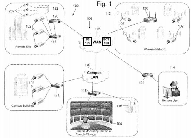
The WAN 108 includes a data storage system 109. In one embodiment, the data storage system 109 can be Amazon's Simple Storage Service (Amazon S3) storage for the Internet. The network camera system 100 stores video and/or images on S3. Amazon S3 provides a simple web services interface that can be used to store and retrieve any amount of data, at any time, from anywhere on the web. Users of the network camera 100 can access the same highly scalable, reliable, fast, inexpensive data storage infrastructure that Amazon uses to run its own global network of web sites.
Network 106 may also include a wireless network 112 that includes network cameras 102 with wireless communication capabilities. Network 106 establishes multiple network communications paths. The following descriptions of network camera102 apply also to network camera 102′. Network 106 is not limited to the configuration depicted, but may include various configurations and types of networks. A remote user 114 may also be connected to network cameras 102 through WAN108. Network cameras 102 may be connected to a remote storage unit 116 (i.e., a network data store). Cameras 102-102′ may operate in the visual range of the electromagnetic spectrum or may include other ranges including infrared (IR) and ultraviolet (UV). Voice recorder may be used in conjunction with the images acquired by cameras 102 to identify a person. The voice recorder is not required and zero to any number of voice recorders could be used. Network camera system 100may also include various switches 118 and routers 120 to facilitate communication over network 106.
In operation, network cameras 102 capture various fields of view and generate data representing the fields of view. Certain applications may require substantially continuous operation of network camera 102. The data is communicated to central monitoring station 104, in which a user may view video or images, generated from the data, depicting the fields of view. Also, the data may be communicated to remote user 114 to generate images of the fields of view. The data may be stored in the web data storage system 109 or alternatively stored on a remote storage unit 116 and later accessed by a user.
Further, the WAN 108 includes an elastic compute cloud (EC2) 150 that enables the camera system 100 to increase or decrease video processing capacity within minutes, not hours or days. The system can commission one, hundreds or even thousands of server instances simultaneously to perform deep searching of images to locate a particular individual captured by the cameras, for example. The system can select a configuration of memory, CPU, instance storage, and the boot partition size that is optimal for its choice of operating system and application. The compute cloud offers a highly reliable environment where replacement processor instances can be rapidly and predictably commissioned. The Amazon embodiment runs within Amazon's proven network infrastructure and datacenters and Amazon EC2's Service Level Agreement commitment is 99.95% availability for each Amazon EC2 Region. Moreover, on-Demand Instances let security camera users or operators pay for compute capacity by the hour with no long-term commitments. This frees the system operator from the costs and complexities of planning, purchasing, and maintaining hardware and transforms what are commonly large fixed costs into much smaller variable costs. On-Demand Instances also remove the need to buy "safety net" capacity to handle periodic traffic spikes. Other features such as Auto Scaling allow the camera system 100 to automatically scale its Amazon EC2 capacity up or down according to predefined conditions. With Auto Scaling, the system of FIG. 1 can ensure that the number of Amazon EC2 instances needed scales up seamlessly during demand spikes to maintain storage size or video analytic performance, and scales down automatically during demand lulls to minimize costs. Auto Scaling is particularly well suited for security monitoring applications that experience hourly, daily, or weekly variability in usage. The EC2 150 also provides Elastic Load Balancing, which automatically distributes incoming application traffic across multiple Amazon EC2 instances. It enables the system to achieve even greater fault tolerance in video processing, seamlessly providing the amount of load balancing capacity needed in response to incoming camera video traffic. Elastic Load Balancing detects unhealthy instances within a pool and automatically reroutes traffic to healthy instances until the unhealthy instances have been restored.
Although the above embodiments have been described, network camera 102 is not limited to the above embodiments. Network camera 102 may include any camera system capable of analyzing the content of video data to detect motion or another event of interest, and capable of generating more than one quality level of video data.
FIG. 2 shows an exemplary telepresence conferencing system. The system has a wide field display 150 that provides viewers with an immersive 180 degree view of participants on the other side of the call. A wide view camera 160 captures a 180 degree view of participants and transmits such video to the other side of the conference call. The wide view camera160 can be one camera fitted with wide angle lens and suitable distortion removing image processor, or can be three separate camera each capturing left, center and right views, respectively. The system can have optional lights 162 to provide lighting to provide high quality images of the physical participants. In one embodiment, the system has desks with a series of surfaces 152 that form an oval physical table space while the display 150 shows the virtual participants. In another embodiment, the system has desks with a series of surfaces 152 that form a semicircular physical table space while the display 150 shows the virtual participants and a matching virtual table space that mirrors the semicircular physical table. The surface 152 includes computers 154, 158 and 164 such as laptop computers. The table also includes an LCD control panel156 that allows users to control and operate the conferencing system.

In one embodiment, the conferencing system includes a 3D scanner 166. The scanner allows the participants to share 3D shape information with others. The 3D scanner 166 transmits 3D shape data that can be displayed on the display 150 and manipulated using suitable 3D imaging or CAD programs. The purpose of a 3D scanner is usually to create a point cloud of geometric samples on the surface of the subject. These points can then be used to extrapolate the shape of the subject (a process called reconstruction). If color information is collected at each point, then the colors on the surface of the subject can also be determined. Like cameras, they have a cone-like field of view, and like cameras, they can only collect information about surfaces that are not obscured. While a camera collects color information about surfaces within its field of view, 3D scanners collect distance information about surfaces within its field of view. The "picture" produced by a 3D scanner describes the distance to a surface at each point in the picture. Together with distance, which corresponds to the r component, these spherical coordinates fully describe the three dimensional position of each point in the picture, in a local coordinate system relative to the scanner.
Also, more details on the 3D scanner of FIG. 2 are discussed next. The system can work with a variety of 3D scanners to communicate shape information with remote conferencing participants. The two types of 3D scanners are contact and non-contact. Non-contact 3D scanners can be further divided into two main categories, active scanners and passive scanners. There are a variety of technologies that fall under each of these categories. Contact 3D scanners probe the subject through physical touch. A CMM (coordinate measuring machine) is an example of a contact 3D scanner. It is used mostly in manufacturing and can be very precise. The disadvantage of CMMs though, is that it requires contact with the object being scanned. Thus, the act of scanning the object might modify or damage it. This fact is very significant when scanning delicate or valuable objects such as historical artifacts. The other disadvantage of CMMs is that they are relatively slow compared to the other scanning methods. Physically moving the arm that the probe is mounted on can be very slow and the fastest CM Ms can only operate on a few hundred hertz. In contrast, an optical system like a laser scanner can operate from 10 to 500 kHz. Non-contact scanners can be active scanners that emit radiation or light and detect its reflection in order to probe an object or environment. Possible types of emissions used include light, ultrasound or x-ray. A time-of-flight lidar scanner may be used to scan buildings, rock formations, etc., to produce a 3D model. The lidar can aim its laser beam in a wide range: its head rotates horizontally, a mirror flips vertically. The laser beam is used to measure the distance to the first object on its path. The time-of-flight 3D laser scanner is an active scanner that uses laser light to probe the subject. At the heart of this type of scanner is a time-of-flight laser rangefinder. The laser rangefinder finds the distance of a surface by timing the round-trip time of a pulse of light. A laser is used to emit a pulse of light and the amount of time before the reflected light is seen by a detector is timed. Since the speed of light c is a known, the round-trip time determines the travel distance of the light, which is twice the distance between the scanner and the surface. The laser rangefinder only detects the distance of one point in its direction of view. Thus, the scanner scans its entire field of view one point at a time by changing the range finder's direction of view to scan different points. The view direction of the laser rangefinder can be changed either by rotating the range finder itself, or by using a system of rotating mirrors. The latter method is commonly used because mirrors are much lighter and can thus be rotated much faster and with greater accuracy. Typical time-of-flight 3D laser scanners can measure the distance of 10,000˜100,000 points every second. A triangulation 3D laser scanner is also an active scanner that uses laser light to probe the environment. With respect to time-of-flight 3D laser scanner the triangulation laser shines a laser on the subject and exploits a camera to look for the location of the laser dot. Depending on how far away the laser strikes a surface, the laser dot appears at different places in the camera's field of view. This technique is called triangulation because the laser dot, the camera and the laser emitter form a triangle. The length of one side of the triangle, the distance between the camera and the laser emitter is known. The angle of the laser emitter corner is also known. The angle of the camera corner can be determined by looking at the location of the laser dot in the camera's field of view. These three pieces of information fully determine the shape and size of the triangle and gives the location of the laser dot corner of the triangle. In most cases a laser stripe, instead of a single laser dot, is swept across the object to speed up the acquisition process. In a Conoscopic system, a laser beam is projected onto the surface and then the immediate reflection along the same ray-path are put through a conoscopic crystal and projected onto a CCD. The result is a diffraction pattern, that can be frequency analyzed to determine the distance to the measured surface. The main advantage with Conoscopic Holography is that only a single ray-path is needed for measuring, thus giving an opportunity to measure for instance the depth of a finely drilled hole. Structured-light 3D scanners project a pattern of light on the subject and look at the deformation of the pattern on the subject. The pattern may be one dimensional or two dimensional. An example of a one dimensional pattern is a line. The line is projected onto the subject using either an LCD projector or a sweeping laser. A camera, offset slightly from the pattern projector, looks at the shape of the line and uses a technique similar to triangulation to calculate the distance of every point on the line. In the case of a single-line pattern, the line is swept across the field of view to gather distance information one strip at a time. Modulated light 3D scanners shine a continually changing light at the subject. Usually the light source simply cycles its amplitude in a sinusoidal pattern. A camera detects the reflected light and the amount the pattern is shifted by determines the distance the light traveled. Modulated light also allows the scanner to ignore light from sources other than a laser, so there is no interference. Photometric systems usually use a single camera, but take multiple images under varying lighting conditions. These techniques attempt to invert the image formation model in order to recover the surface orientation at each pixel. This sort of 3D scanning is based on the principles of photogrammetry. It is also somewhat similar in methodology to panoramic photography, except that the photos are taken of one object on a three-dimensional space in order to replicate it instead of taking a series of photos from one point in a three-dimensional space in order to replicate the surrounding environment. Alternatively, computed tomography, microtomography, magnetic resonance imaging (MRI) techniques can be used in the 3D scanner.
In addition, a rapid prototyping machine can be installed to render the 3D data into a physical model for the participants to touch and feel. Rapid prototyping is the automatic construction of physical objects using additive manufacturing technology. The first techniques for rapid prototyping became available in the late 1980s and were used to produce models and prototype parts. Today, they are used for a much wider range of applications and are even used to manufacture production-quality parts in relatively small numbers. The use of additive manufacturing technology for rapid prototyping takes virtual designs from computer aided design (CAD) or animation modeling software, transforms them into thin, virtual, horizontal cross-sections and then creates successive layers until the model is complete. It is a WYSIWYG process where the virtual model and the physical model are almost identical.
With additive manufacturing, the machine reads in data from a CAD drawing and lays down successive layers of liquid, powder, or sheet material, and in this way builds up the model from a series of cross sections. These layers, which correspond to the virtual cross section from the CAD model, are joined together or fused automatically to create the final shape. The primary advantage to additive fabrication is its ability to create almost any shape or geometric feature.
Prototyping technologies |
Base materials |
Selective laser sintering (SLS) |
Thermoplastics, metals powders |
Fused deposition modeling (FDM) |
Thermoplastics, eutectic metals. |
Stereolithography (SLA) |
photopolymer |
Laminated object manufacturing (LOM) |
Paper |
Electron beam melting (EBM) |
Titanium alloys |
3D printing (3DP) |
Various materials |
Smart Network Camera
Network camera 102 will now be described in more detail with reference to FIG. 3A. Network camera 102 includes an imager 200 (such as CCD or CMOS image sensors), a video analytics engine 210, a video compression engine 220, a server 230, and a power module with input/output interface and control 240. The module 240 can be a Power over Ethernet module that integrates power and network communication, or alternatively can be separate power and Ethernet connection. Network camera 102 includes a camera housing (not shown); and all or portions of systems 200-240 may be contained within the housing. Imager 200 may include a wide variety of units for capturing a field of view and for generating video information including digital data and analog signals. For example, imager 200 may generate information according to NTSC/PAL formats and mega-pixel formats. Imager 200 may include programmable imagers, high-definition imagers, no/low light sensors, and specialized imagers that are more sensitive to certain spectrums of light. Video compression engine 220 may include a scalable video codec with video compression using an advanced video standard such as H.264. Server 230 may be an SoC with external memory running an OS such as Linux. The server 230 can store video images in memory, solid state disk such as Flash, or a hard drive. The server 230 allows a remote user to retrieve the video over the network, or alternatively the server 230 can transmit video images and video metadata to the cloud storage S3 on a periodic basis. Power module 240 may include any system for receiving and distributing electrical power to various systems of network camera 102. Power may be DC power, including Power over Ethernet (PoE), or AC power. Input/output interface and control system 210 includes various hardware and software configurations to facilitate numerous types of communication including Internet; Ethernet; universal serial bus (USB); wireless; asynchronous transfer mode (ATM); Packet over SONET/SDH (POS); pan, zoom, tilt (PZT); and audio information input/output interface and control may be implemented in hardware and software to allow a user to configure operation of network camera 102.
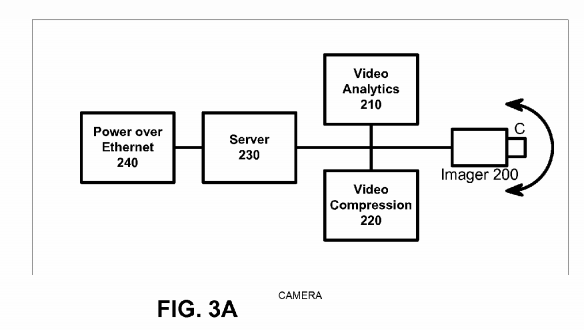
In an alternative embodiment, a video server may be used in place of network camera 102, in which multiple imaging systems 200 capturing different fields of view are connected to video server. The video compression engine 220 may also include video encryption capabilities to prevent unauthorized viewing of video information. The video compression engine 220may be programmable and may be capable of producing multiple quality levels of video data, including higher quality video data and lower quality video data. A quality level refers to multiple video parameters including resolution, frame rate, bit rate, and compression quality. For example, high quality video data may represent D1 resolution video recorded at 30 frames-per-second (fps) and low quality video data may represent CIF resolution video recorded at 5 fps but are not limited to the parameters above. The video compression engine 220 can generate high quality video data representing a person in the field of view while simultaneously generating a low quality video data representing background scene images of the field of view.
The video analytics engine 210 analyzes the video data produced by imager 200 to detect whether a predefined event or object of interest is being captured by imager which captures high definition video. Video analytics engine 210 generates metadata that describe the content of video data. The metadata produced by video analytics engine 210 may be a textual and semantic description of the content of the video. Video analytics engines of different network cameras 102 may have different analytic capabilities. Multiple events of interest may be defined, and more than one event of interest may occur at a particular time. Also, the nonoccurrence of one event leaves open the possibility of the occurrence of a second event. The metadata may be supplied to data storage system or the Amazon S3 web storage. The metadata representing an arbitrary frame n can be associated with video data representing frame n. Thus, the metadata may be searchable to allow a user to efficiently search and semantically browse large video archives.
An event of interest that video analytics engine 210 detects may be as simple as motion in the field of view. Video analytics engine 210 may also implement blob detection (e.g. detecting a group of moving pixels as a potential moving object, without identifying what type of object it is), lighting change adjustment, and geometric calibration based on object size in the field of view to distinguish objects based on types. For example, video analytics engine 210 may be able to classify an object as a human being, a vehicle, or another type of object and be able to recognize an object when the object appears in any portion within the field of view of network camera 102. Furthermore, video analytics engine 210 may be able to recognize certain identifiable features of an object such as, for example, human faces and vehicle license plates. Video analytics engine 210may be able to recognize when imager 200 is capturing a new object and assign a unique object ID to the new object. Video analytics engine 210 may be able to recognize the speed and trajectory at which an object moves. Video analytics engine 210 may be able to recognize events such as perimeter intrusion, object movement in a particular direction, objects approaching one another, a number of objects located in a specified area, objects left behind, and object removal. Video analytics engine 210 can also recognize specific locations, or coordinates, within the field of view where an event or object of interest is being captured, or a combination of objects and events, as defined by a rule.
When video analytics engine 210 detects an event or object of interest within the video data, video analytics engine 210generates metadata that correspond to the event or object of interest and supplies the metadata to an action engine, which can be rules based in one embodiment. For example, the rules can send an alert (e.g., instructions to generate one or both of a visual display and an audible sound) to central monitoring station 104 or remote user 114, store video data in Amazon S3 for X period of time, among others. For example, a user may define the following rule: when a human being enters a defined perimeter, store high resolution video data representing the intrusion, alert central monitoring station 104 of the intrusion, generate a short video clip of the intrusion and send the video clip to central monitoring station 104, and store in the Web storage S3 the video data representing the intrusion. Or, a user may define the following rule: when no event or object of interest is being captured, store low resolution video data and send no video data to central monitoring station104. Because video analytics engine 210 can detect various objects and events, a wide variety of rules may be defined by a user and each rule can have different storage quality settings. Also, because multiple events of interest may occur simultaneously, a rule may correspond to a combination of events.
The video compression engine 120 can be a scalable video codec to generate multiple quality levels using H.264 SVC. For example, network camera 102 initially generates high resolution video data and subsequently, the quality level of portions of the video data that represent the nonoccurrence of an event of interest are saved in low resolution to save storage space. Storage capacity needs can be reduced even for applications that require substantially continuous operation of network camera 102. For example, when an event of interest is captured, the content aware storage system can record the event at a high resolution level. When an event of interest is not being captured, the content aware storage system can record the video data at a low resolution level. The quality level of stored data, therefore, can be matched to the importance of the content.
In operation, imager 200 captures a field of view and generates video data. Frames of the video data are time-stamped so that metadata generated by video analytics engine 210 may be synchronized with video data generated by imager 200. Video analytics engine 210 analyzes the video data generated by imager 200 and generates metadata based upon the content of the video data. The video compression engine 220 also receives the video data generated by imager 200 and generates scalable video data that can be subsequently be saved at differing resolution. The metadata is communicated to the server to determine whether a rule has been violated (i.e., whether an event or object of interest detected by video analytics engine 210 requires action).
Referring now to exemplary H.264 encoder cores shown in FIGS. 3B-3C, the initial step is the generation of a prediction. The baseline H.264 encoder uses two kinds of prediction: intra prediction (generated from pixels already encoded in the current frame) and inter prediction (generated from pixels encoded in the previous frames).
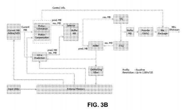

A residual is then calculated by performing the difference between the current block and the prediction. The prediction selected is the one that minimizes the energy of the residual in an optimization process that is quite computationally intensive.
A linear transform is then applied to the residual. Two linear transforms are used: Hadamard and a transform derived from the discrete cosine transform (DCT). The coefficients resulting from the transformations are then quantized, and subsequently encoded into Network Abstraction Layer (NAL) units. These NALs include context information—such as the type of prediction—that is required to reconstruct the pixel data. The NAL units represent the output of the baseline H.264 encoding process.
Meanwhile, inverse quantization and transform are applied to the quantized coefficients. The result is added to the prediction, and a macroblock is reconstructed. An optional deblocking filter is applied to the reconstructed macroblocks to reduce compression artifacts in the output. The reconstructed macroblock is stored for use in future intra prediction and inter prediction. Intra prediction is generated from unfiltered reconstructed macroblocks, while inter prediction is generated from reconstructed macroblocks that are filtered or unfiltered.
Intra prediction is formed from pixels that were previously encoded. Two kinds of intra predictions are used: intra16×16 and intra4×4. In intra16×16, all the pixels already encoded at the boundary with the current block can be used to generate a prediction. These are shown shaded in the figure below. The core can generate the four modes of the intra16×16 prediction. In intra4×4, 16 4×4 blocks of prediction are generated from the pixels at the boundaries of each 4×4 prediction block and boundary pixels are used in intra16×16 and intra4×4 intra prediction modes.
The inter prediction is generated from motion estimation. At the heart of video compression, motion estimation is used to exploit the temporal redundancy present in natural video sequences. Motion estimation is performed by searching for a 16×16 area of pixels in a previously encoded frame so that the energy of the residual (difference) between the current block and the selected area is minimized.
The core can search an area 32×32 pixels wide, down to ¼ pixel of resolution (−16.00, +15.75 in both X and Y direction). Pixels at ¼ resolution are generated with a complex interpolation filter described in the ITU-T H.264 specification.
The Hadamard transform and an integer transform derived from the DCT and their descriptions can be found in the ITU-T H.264 standard, the content of which is incorporated by reference. Both transforms (and their inverse functions) can be performed by using only additions, subtractions and shift operations. Both quantization and its inverse are also relatively simple and are implemented with multiplication and shifts.
H.264 encoding can be essentially divided into two independent processes: motion estimation and compensation, and variable length encoding. The motion estimation submodule of the core consists of two stages: integer pixel motion estimation followed by a refining step that searches for matches down to ¼ pixel resolution. The integer search unit utilizes a 4 step search and sums of absolute difference (SAD) process to estimate the motion vector. Similar to the case of motion estimation, SADs are used to search for the intra prediction mode that best matches the current block of pixels.
The resultant bitstream is assembled into NAL units and output in byte stream format as specified in Annex B of the ITU-T H.264 specification. Each NAL unit contains context information about the type of prediction, motion vectors, Quantisation Parameter delta, and the Context Adaptive Variable Length Coded (CAVLC) luma and chroma coefficients. Most of the encoded bits in each macroblock are devoted to the CAVLC coefficients. CAVLC coding operates on 4×4 blocks and scans the coefficients in zig-zag order. Each 4×4 block comprises the following elements:
-
the number of non-zero coefficients
-
number of trailing ones (up to 3)
-
sign of each trailing one (up to 3)
-
the level code of each non-zero coefficient
-
the zero run code preceding each non-zero coefficient
For high definition video, the core requires an external memory, whose interface can be easily interfaced to the AMBA AHB with a minimal amount of extra logic. The interface is also designed to be tolerant of latencies and delays typical of a shared bus. The external memory is likely to be, in many cases, a type of SDRAM rather than SRAM. One of the characteristics of SDRAM is for the memory to behave essentially like a SRAM provided that accesses are confined within a page. Only when crossing a page boundary will the penalty of extra cycles be incurred due to a precharge. Therefore the core sorts all its memory accesses in a way that minimizes page boundary crossings, achieving performance closer to one that would be obtained if it was connected to SRAM. The memory controller can postpone precharging as long as accesses are confined to the same page. Additionally, the external memory interface can be clocked at a different frequency from the main core. Other features include block skipping for lower bit count and multiple slice encoding for error resilience. A deblocking filter is also used in order to improve image quality at low bit rates.
FIG. 3D shows another high definition H.264 encoder with a parallel-processing architecture. The encoder of FIG. 3D is an application-specific VLSI architecture for H.264/AVC video encoding. The architecture is discussed in Youn-Long Steve Lin et al's book VLSI Design for Video Coding: H.264/AVC Encoding from Standard Specification to Chip, published by Springer; 1st Edition (Dec. 1, 2009), the content of which is incorporated by reference.

FIG. 3E shows an exemplary video analytics sub-system implemented as an FPGA or ASIC. The VA engine includes a plurality of engines, including an engine to perform image flow, up/down scaling and windowing; an engine to perform image flow conditioning and noise filtering, including gain control and contrast modification; an engine to perform foreground-background separation; an engine to perform binary morphological filtering, with size classification and contour-structure shaping; an engine to perform multi-event/object signature and/or feature extraction; and an engine to perform event/object-focused enhancement. To provide better performance, an engine to perform application-specific event/object-based control is also provided. The above engines are implemented in hardware for speed reasons. In FIG. 3E, the front-end and the mid layers are accelerated by hardware. The back-end operations such as multi-object tracking and event/object classification are done on a processor or DSP for flexibility.
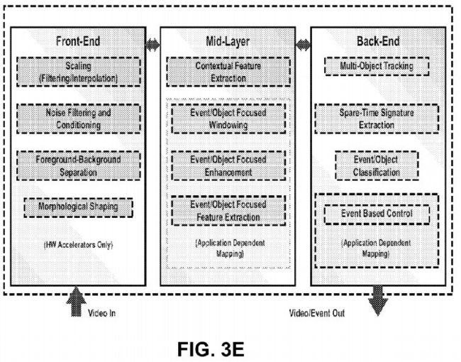
These engines can be used to flexibly create a multithread coprocessor pipeline for demanding image flow processing. The IP cores can be deployed in almost arbitrary order and configured during the design and customization of various analytics engines.
FIG. 3F shows an exemplary Cellular Neural Network (CNN) suitable for image processing. Cellular arrays are usually defined on a spatially discrete square (rectangular) grid; however, hexagonal and triangular arrangements can also be considered. These grids are the only regular contiguous tessellations of the plain based on congruent polygons alone. Other grid-types can also be created based on non-regular congruent polygons or from a regular vertex grid through discrete geometrical transformations: rotations and translations. A number of these grids can be mapped on a typical eight-neighbor rectangular structure with periodic space-variant connections.

FIGS. 3G-3H shows an exemplary digital CNN. The CNN has a mixer which contains cell values for the next updates, a memory unit that contains a belt of the cell array, a template memory, and an arithmetic unit. The processors can be connected on a grid. Depending on the template size, each mixer unit stores the surrounding cells of the currently processed one, while the memory units store a one or two row-high belt from the given layer. Using this structure the I/O requirements of the processor are reduced to p load and p store operations per cell update. The optimized template memory contains only the parameters which are necessary to perform the computations, while the modified arithmetic units make efficient computation of the different type multilayer dynamics possible.


FIG. 3L shows an ALU for the processor of FIG. 3G, while a block level structure of the arithmetic unit for the processor of FIG. 3H is shown in FIG. 3I. To reduce the clock cycle time of the arithmetic unit, pipeline technique is used. The computation of the derivatives can be divided into the following three parts: (i) computation with the zero neighborhood (intra- and interlayer) connections, (ii) computation with the diffusion-type template, and (iii) computation with the Gauss-type templates. Each layer has a separated and optimized arithmetic core which is connected to the mixer and memory units of the other layers according to the existing connections between the layers. The simplest element of the arithmetic unit is the intralayer block, which computes the inter- and intralayer zero neighborhood connections. This unit contains one multiplier for each connection, and the multiplied values are summed by an adder tree.
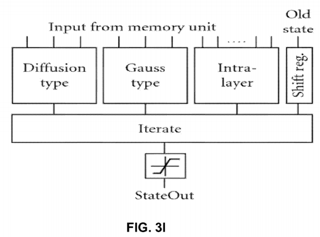

FIG. 3J shows the structure of the optimized arithmetic unit to compute the diffusion-type template (pipeline registers are not shown for simplicity). Due to the symmetry properties of the diffusion-type template, the computation can be performed by the optimized circuit shown in FIG. 3J.
Multiplication with 2 and −12 is carried out by shifting operations and only one multiplier is required to compute the 3×3 template operation. This solution reduces the number of required multipliers from 3 to 1. Additionally, the number of clock cycles required to compute a new value is also reduced from 3 to 1 clock cycle, which significantly increases the computing performance of the processor.
FIG. 3K shows an optimized arithmetic unit to compute the Gauss-type template (pipeline registers are not shown for simplicity). The Gaussian template is also symmetrical but the ratio of the coefficient values is not an integer number. Therefore, at first the equally weighted state values are summed then these partial results are multiplied; finally the multiplied values are summed again. By using this optimized circuit shown in FIG. 3K, the number of multipliers is still three but the length of the computation cycle is reduced to one clock cycle.

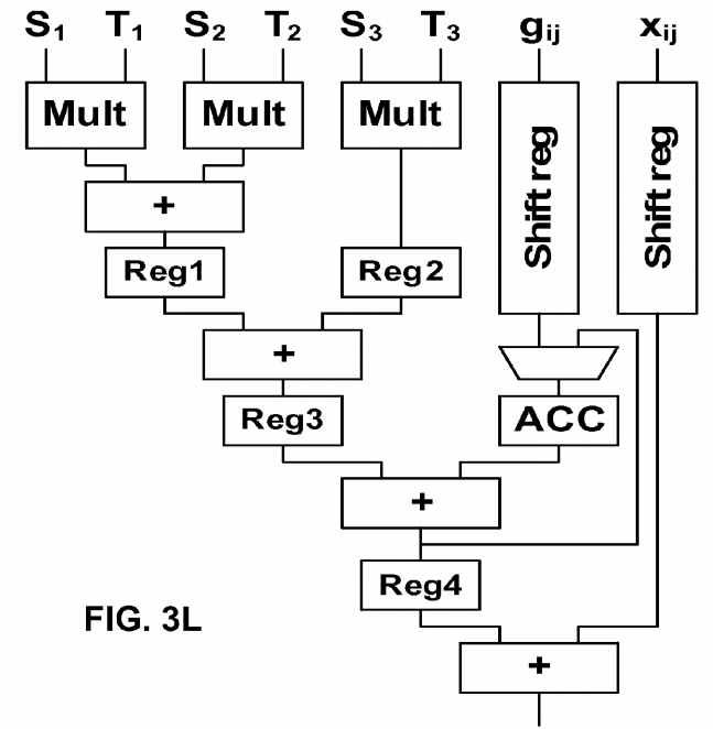
FIG. 3M shows another exemplary Cellular Neural Network (CNN) suitable for image processing. This system is a reduced version of a Hopfield Neural Network. The local connections between a cell and the neighbors in this implementation of this technology are easier than in the case of Hopfield Neural Networks.

Other main important units for developing the CNN are the integrator and linear sigmoid function. To implement an integrator in HDL a register is used. The integrator unit sums the result in each new cycle with previous values of the register.
According to the length of M0 and M1, the length of the integrator register should be 32 bit. The following code below is obtained after synthesis and is like an 8 integrator that works concurrently.
always @(posedge clk) |
||
begin |
||
for (j=0;j<=7;j=j+1) |
||
begin |
||
res[j] = S2[j]; |
||
end |
||
The term of S2 is the sum of C(TA,Y) and C(TB,U) from the previous cycle.
A sigmoid function can be implemented as an if-then rule. The following code below shows the way this unit operates. "Greater than values" will be limited by this procedure between +1 and −1.
for (j=0;j<=7;j=j+1) |
||
begin |
||
if (res[j]>32′sh00000_000) // > 0 |
||
begin |
||
Y[j]=16′h1_000; // +1 |
||
res[j]=32′h00001_000; |
||
end |
||
if (res[j]==32′sh00000_000) // = 0 |
||
begin |
||
Y[j]=16′h0_000; // 0 |
||
res[j]=32′h00000_000; |
||
end |
||
if (res[j]<32′sh00000_000) // < 0 |
||
begin |
||
Y[j]=16′hf_000; // −1 |
||
res[j]=32′hfffff_000; |
||
end |
||
End |
||
In these units the "res" vector is a temporary register for simulating the integrator and "Y" variable is a memory for storing CNN output state.
The convolution for feedback and control templates are as follows:
// 1×3 Convolution Module |
||
module conv2 (conv,VA1,VA2,VA3,Y1,Y2,Y3); |
||
output [17:0] conv; //17 |
||
input [15:0]VA1; |
||
input [15:0]VA2; |
||
input [15:0]VA3; |
||
input [15:0]Y1; |
||
input [15:0]Y2; |
||
input [15:0]Y3; |
||
wire signed [17:0] conv; |
||
wire signed [15:0] out1; |
||
wire signed [15:0] out2; |
||
wire signed [15:0] out3; |
||
signe_mul MUL1(out1,VA1,Y1); |
||
signe_mul MUL2(out2,VA2,Y2); |
||
signe_mul MUL3(out3,VA3,Y3); |
||
assign conv = out1+out2+out3; |
||
endmodule |
||
// resule range [−7,+7] accuracy 12bit Fixed Float |
||
module signe_mul (out,a,b); |
||
output [15:0] out; |
||
input [15:0] a; |
||
input [15:0] b; |
||
wire signed [15:0] out; |
||
wire signed [31:0] mul_out; |
||
assign mul_out = a*b; |
||
assign out = {mul_out[31],mul_out[26:12]}; |
||
endmodule |
||
FIG. 4 shows a second exemplary implementation of the camera. The output from imager (CMOS or CCD) 200 is digitized and provided to an FPGA or ASIC device that has two portions: video analytics DSP 310 and H.264 encoder 320. The encoder 320 and a CPU 330 can share memory 350. The data can be transmitted over Ethernet and power can be supplied by a power over Ethernet (PoE) chip 340. The system of FIG. 3 is cost effective and provides high performance. The FPGA version provides field upgradability. In one embodiment, the CPU 330, DSP 310 and encoder 320 are in one single ASIC. In another embodiment, the CPU 330 is a separate IC, while the DSP 310 and encoder 320 are in an FPGA. Any combinations of ASIC and FPGA can be done as well.
FIG. 5 shows a third implementation of the camera. The output from imager (CMOS or CCD) 200 is digitized and provided to a CPU/GPU (graphic processing unit) device 360 where the parallel processes used to produce graphics imagery by the GPU are used instead to perform arithmetic calculations.

Additionally, one or more GPUs 312 and 330 can communicate with the CPU 360 over a bus such as PCIe bus to offload processing work from the CPU 360. The GPUs, working in concert with the system's CPUs accelerate enabled applications beyond traditional graphics and video processing. This enables balanced platforms to run computationally-intensive tasks more efficiently, providing a better application experience to the end user. The imager 200, the memory 350, and PoE 340can communicate over the bus as well.
The system of FIG. 5 provides high performance and field upgradability. In one embodiment, the CPU and GPUs are in one single IC device with a heterogeneous multicore microprocessor architecture, combining a general purpose processing core(s) and basic graphics core(s) into one processor package, with different clocks for the graphics core and the central processing core. In this embodiment, AMD's Fusion series processor includes on-chip graphics core that can be changed without re-design of the whole core. In this embodiment, hardware decoders of MPEG2, VC-1 and H.264 video streams are included, while H.264 encoding is done on the GPUs with supported software. In another embodiment, the CPU 360 is a separate IC, while the GPUs are in a separate IC. Any combinations of CPU, GPU and FPGA can be done as well.
The implementation of FIG. 5 uses GPUs such as those in video cards which are designed to perform fast execution of integer and floating-point arithmetic. This capability enables the video adapter to quickly compute color, shading, texture, and other aspects of a changing image and render these in real time to the screen—thereby creating lifelike multimedia experiences. On many PCs, especially business PCs, much of this capability remains unused because business graphics only rarely need these full-bore advanced video capabilities, which means that the GPU and related hardware are available to be harnessed for non-video computation such as stream computing. Stream computing (or stream processing) refers to a class of compute problems, applications or tasks that can be broken down into parallel, identical operations and run simultaneously on a single processor device. These parallel data streams entering the processor device, computations taking place and the output from the device define stream computing. Stream computing takes advantage of a SIMD methodology (single instruction, multiple data) whereas a CPU is a modified SISD methodology (single instruction, single data); modifications taking various parallelism techniques into account. The benefit of stream computing stems from the highly parallel architecture of the GPU whereby tens to hundreds of parallel operations are performed with each clock cycle whereas the CPU can work only a small handful of parallel operations per clock cycle.

FIG. 5C shows an exemplary multimedia processor that can handle H.264 encoding as well as being a 3D graphics controller for handheld devices such as cellular telephones or gaming devices, among others. The device is a super integrated SoC (System On a Chip) aimed at providing high performance multimedia functionality and low power consumption for Personal Multimedia Digital Assistance. The device incorporates 32 bit CPU processor with integrated DSP support, H.264 Decoder, JPEG Decoder, 2D Graphic engine, Sound Mixer, CRT controller with OSD, Video Encoder, Video Decoder Interface Module, USB Host/Device and I/O peripheral components. EAGLE can reduce system cost significantly through eliminating not only system control CPU, but also graphic IC, Sound IC and Video Encoder as well as USB. EAGLE helps system designer reduce its engineering effort and time in developing a new system by adding only memory and I/O devices such as LCD panel, Flash, among others. This device is optimized for multimedia player, portable karaoke, portable and arcade game.

One embodiment features a 32 bit Processor Core 750 based On EISC Instruction Set Architecture providing High Performance Integer Processing Core with DSP Capabilities-5-Stage Pipelining, Harvard Architecture, 16 General Purpose Registers (GPR) and 9 Special Purpose Registers (SPR). An MJPEG decoder 752 is connected over an AHB bus 770. DMA controller 754 also communicates over the AHB bus 770. A UART/timer/GPIO/RTC/SPI/USB and flash card interface unit 756 is provided. A sound controller 758, an H.264 decoder 760 is provided to provide high performance playing of H264 video streams. A 3D graphic processing unit (GPU) 762 can render 3D graphics for gaming and can also be used to encode H.264 video streams. An LCD display controller 726 can drive an LCD or suitable display. The device of FIG. 5C supports AMBA 2.0. The AHB Master On-Chip Cache Controller provides Separated On-Chip Instruction/Data Cache4-way Set Associative, 8 KByte Instruction Cache, 8 KByte Data Cache On-Chip Memory Management Unit Memory Protection Capabilities Based on Memory Bank and Sub-banking Scheme Separated On-Chip Instruction/Data TLB, 4-Way Set Associative, 128-Entry DSP function Saturated Add, Average, Sum of Product, PackShift/Rotate, ABS, Min/MaxAddress Unit-Next Address, Reverse Address, Auto address32 bit signed/unsigned multiply32 bit signed multiply and accumulate capabilities.
The CRT Controller 726 supports VGA, TFT LCD and NTSC/PAL Display Monitor and supports high display resolution. It supports VESA DPMS for VGA monitor-Horizontal and Vertical double scan control-Serialization RGB data and 256×32 FIFO controls in CRTC block-Gun Interface Video Signal Processing-Support External Video Sync.
FIG. 6 shows one embodiment of GPU based camera 700. In FIG. 6, a multi-core processor 708 includes CPUs 702 and706 with shared memory 704. The processor 708 communicates over a PCIe bus 710 with one or more graphics chips 720which includes a plurality of GPUs 722 communicating with shared memory 724. A camera 740A also communicates over the PCIe bus 710.
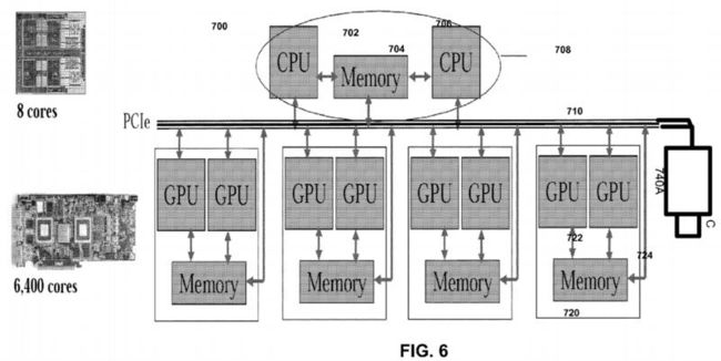
FIG. 7 shows another GPU camera embodiment of FIG. 6. In this embodiment, each of three cameras 740B, 740C and740D is connected to a GPU device and the GPU device 720 in turn performs video analytics and/or encoder operations on the video captured by the camera. The system of FIG. 7 scalably handles a number of cameras in parallel, while keeping overhead costs low.

In one embodiment with two or more cameras, camera parameters (e.g. field of view) are preset to fixed numbers. Each pixel from each camera maps to a cone space. The system identifies one or more 3D feature points (such as a birthmark or an identifiable body landmark) on the patient. The 3D feature point can be detected by identifying the same point from two or more different angles. By determining the intersection for the two or more cones, the system determines the position of the feature point. The above process can be extended to certain feature curves and surfaces, e.g. straight lines, arcs; flat surfaces, cylindrical surfaces. Thus, the system can detect curves if a feature curve is known as a straight line or arc. Additionally, the system can detect surfaces if a feature surface is known as a flat or cylindrical surface. The further the patient is from the camera, the lower the accuracy of the feature point determination. Also, the presence of more cameras would lead to more correlation data for increased accuracy in feature point determination. When correlated feature points, curves and surfaces are detected, the remaining surfaces are detected by texture matching and shading changes. Predetermined constraints are applied based on silhouette curves from different views. A different constraint can be applied when one part of the patient is occluded by another object. Further, as the system knows what basic organic shape it is detecting, the basic profile can be applied and adjusted in the process.
In a single camera embodiment, the 3D feature point (e.g. a birth mark) can be detected if the system can identify the same point from two frames. The relative motion from the two frames should be small but detectable. Other features curves and surfaces will be detected correspondingly, but can be tessellated or sampled to generate more feature points. A transformation matrix is calculated between a set of feature points from the first frame to a set of feature points from the second frame. When correlated feature points, curves and surfaces are detected, the rest of the surfaces will be detected by texture matching and shading changes.
Each camera exists in a sphere coordinate system where the sphere origin (0,0,0) is defined as the position of the camera. The system detects theta and phi for each observed object, but not the radius or size of the object. The radius is approximated by detecting the size of known objects and scaling the size of known objects to the object whose size is to be determined. For example, to detect the position of a ball that is 10 cm in radius, the system detects the ball and scales other features based on the known ball size. For human, features that are known in advance include head size and leg length, among others. Surface texture can also be detected, but the light and shade information from different camera views is removed. In either single or multiple camera embodiments, depending on frame rate and picture resolution, certain undetected areas such as holes can exist. For example, if the patient yawns, the patient's mouth can appear as a hole in an image. For 3D modeling purposes, the hole can be filled by blending neighborhood surfaces. The blended surfaces are behind the visible line.
In one embodiment, each camera is calibrated before 3D detection is done. Pseudo-code for one implementation of a camera calibration process is as follows:
-
Place a calibration sheet with known dots at a known distance (e.g. 1 meter), and perpendicular to a camera view.
-
Take snap shot of the sheet, and correlate the position of the dots to the camera image:
Dot1(x,y,1)←>pixel(x,y)
-
Place a different calibration sheet that contains known dots at another different known distance (e.g. 2 meters), and perpendicular to camera view.
-
Take another snapshot of the sheet, and correlate the position of the dots to the camera image:
Dot2(x,y,2)←>pixel(x,y)
-
Smooth the dots and pixels to minimize digitization errors. By smoothing the map using a global map function, step errors will be eliminated and each pixel will be mapped to a cone space.
-
For each pixel, draw a line from Dot1(x,y,z) to Dot2(x,y,z) defining a cone center where the camera can view.
-
One smoothing method is to apply a weighted filter for Dot1 and Dot2. A weight filter can be used. In one example, the following exemplary filter is applied.
121 242 121
-
Assuming Dot1_Left refers to the value of the dot on the left side of Dot1 and Dot1_Right refers to the value of the dot to the right of Dot1 and Dot1_Upper refers to the dot above Dot1, for example, the resulting smoothed Dot1 value is as follows:
1/16 * ( Dot1 * 4 + Dot1_Left * 2 + Dot1_Right *2 + Dot1_Upper *2 +
Dot1_Down *2 + Dot1_UpperLeft + Dot1_UpperRight +
Dot1_LowerLeft + Dot1_LowerRight)
-
Similarly, the resulting smoothed Dot2 value is as follows:
1/16 * ( Dot2 * 4 + Dot2_Left * 2 + Dot2_Right *2 + Dot2_Upper
*2 + Dot2_Down *2 + Dot2_UpperLeft + Dot2_UpperRight +
Dot2_LowerLeft + Dot2_LowerRight)
In another smoothing method, features from Dot1 sheet are mapped to a sub pixel level and features of Dot2 sheet are mapped to a sub pixel level and smooth them. To illustrate, Dot1 dot center (5, 5, 1) are mapped to pixel (1.05, 2.86), and Dot2 dot center (10, 10, 2) are mapped to pixel (1.15, 2.76). A predetermined correlation function is then applied.