深入解析帧中继ping不通自身ip的原因
作者:Komy-D
出处:http://hi.baidu.com/51cmdshell(转载注明出处)
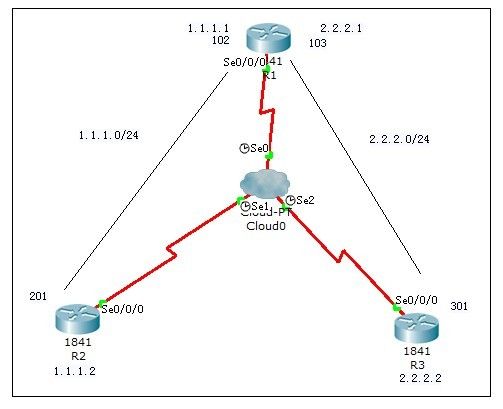
首先在帧中继网云中配置pvc dlci和映射,这里不再赘述
R1配置如下:
!
interface Serial0/0/0
no ip address
encapsulation frame-relay
!
interface Serial0/0/0.102 point-to-point
ip address 1.1.1.1 255.255.255.0
frame-relay interface-dlci 102
!
interface Serial0/0/0.103 point-to-point
ip address 2.2.2.1 255.255.255.0
frame-relay interface-dlci 103
!
R2配置如下:
!
interface Serial0/0/0
ip address 1.1.1.2 255.255.255.0
encapsulation frame-relay
!
R3配置如下:
!
interface Serial0/0/0
ip address 2.2.2.2 255.255.255.0
encapsulation frame-relay
!
R1、R2、R3的s0/0/0接口均为启用状态
配置完毕后,R1与R2、R3能ping通,R2和R3不能ping通。但问题随之而来,R1能ping通自己的两个子接口地址1.1.1.1和2.2.2.1
R1#ping 1.1.1.1
Type escape sequence to abort.
Sending 5, 100-byte ICMP Echos to 1.1.1.1, timeout is 2 seconds:
!!!!!
Success rate is 100 percent (5/5), round-trip min/avg/max = 13/16/25 ms
R1#ping 2.2.2.1
Type escape sequence to abort.
Sending 5, 100-byte ICMP Echos to 2.2.2.1, timeout is 2 seconds:
!!!!!
Success rate is 100 percent (5/5), round-trip min/avg/max = 8/13/17 ms
R2无法ping通自身的物理接口IP地址:
R2#ping 1.1.1.2
Type escape sequence to abort.
Sending 5, 100-byte ICMP Echos to 2.2.2.2, timeout is 2 seconds:
.....
Success rate is 0 percent (0/5)
R3无法ping通自身的物理接口IP地址:
R3#ping 2.2.2.2
Type escape sequence to abort.
Sending 5, 100-byte ICMP Echos to 2.2.2.2, timeout is 2 seconds:
.....
Success rate is 0 percent (0/5)
这是为什么呢?自身子接口的IP可以ping通,物理接口却不行,在我看来,配置R1两个子接口时使用的frame-relay interface-dlci DLCI命令,就把DLCI和子接口关联了起来,形成了子接口IP与DLCI的映射关系。
由于物理接口(R2、R3的配置)默认使用inverse-arp,路由器就会与网云中的帧中继交换机进行lmi通信,获得dlci信息,然后发送inarp包获取目标的IP地址,形成动态映射。这种方式只是与对端的路由进行inarp,而忽略了其本身。
帧中继中通讯是基于DLCI的,它相当于以太网中的物理地址MAC,物理接口中没有自动创建本地接口与DLCI的映射,也就无法通信。子接口配置中由于用的frame-relay interface-dlci DLCI命令,把DLCI和子接口关联了起来,形成了子接口IP与DLCI的映射关系。
这些均为本人的个人见解,不足之处请提出!谢谢
现在在R2、R3中的s0/0/0的接口模式下分别执行
frame-relay map ip 1.1.1.2 201
frame-relay map ip 2.2.2.2 301
创建dlci与本地IP的映射关系,物理接口的本地IP成功ping通:
R2# ping 1.1.1.2
Type escape sequence to abort.
Sending 5, 100-byte ICMP Echos to 1.1.1.2, timeout is 2 seconds:
!!!!!
Success rate is 100 percent (5/5), round-trip min/avg/max = 8/14/18 ms
R3# ping 2.2.2.2
Type escape sequence to abort.
Sending 5, 100-byte ICMP Echos to 1.1.1.2, timeout is 2 seconds:
!!!!!
Success rate is 100 percent (5/5), round-trip min/avg/max = 8/14/18 ms
本文意义不大,算是研究下技术罢了,没有多大的实用价值
但看完本文后你会深入了解到为什么帧中继中ping不通自身IP的疑惑
PS:在wan的其他封装方式中,如ppp、hdlc均可ping通自身ip
关于此问题在ccna中的考题:
When troubleshooting a Frame Relay connection, what is the first step when performing a loopback
test?
A. Set the encapsulation of the interface to HDLC.
B. Place the CSU/DSU in local-loop mode.
C. Enable local-loop mode on the DCE Frame Relay router.
D. Verify that the encapsulation is set to Frame Relay.
Answer: A
补充:如果想让R2和R3能通互想ping通,可添加如下命令:
R2:
R2(config)#frame-relay map ip 2.2.2.1 201 //添加指向R1的103子接口的arp映射关系。
R2(config)#ip route 2.2.2.0 255.255.255.0 1.1.1.1 //添加指向2.2.2.0网段的路由。
R2(config)#do sh frame-relay map
Serial1/0 (up): ip 2.2.2.1 dlci 201(0xC9,0x3090), static,
CISCO, status defined, active
Serial1/0 (up): ip 1.1.1.2 dlci 201(0xC9,0x3090), static,
CISCO, status defined, active
Serial1/0 (up): ip 1.1.1.1 dlci 201(0xC9,0x3090), dynamic,
broadcast,, status defined, active
R3(方法同上):
R3(config)#frame-relay map ip 1.1.1.1 301
R3(config)#ip route 1.1.1.0 255.255.255.0 2.2.2.1
R3(config)#do sh frame-relay map
Serial1/0 (up): ip 1.1.1.1 dlci 301(0x12D,0x48D0), static,
CISCO, status defined, active
Serial1/0 (up): ip 2.2.2.2 dlci 301(0x12D,0x48D0), static,
CISCO, status defined, active
Serial1/0 (up): ip 2.2.2.1 dlci 301(0x12D,0x48D0), dynamic,
broadcast,, status defined, active
