树莓派官方自带gpio驱动bcm2708_gpio.c原理分析 linux gpio架构 gpio子系统
[转载请注明出处 http://www.cnblogs.com/umbrellary/p/5164148.html ]
对树莓派gpio的操作有好多方法,比如mmap映射cpu内存,编写内核驱动模块等。这里推荐一篇文章http://blog.csdn.net/xukai871105/article/details/18517729
其实树莓派官方使用linux内核gpio驱动框架内置了一个驱动,让我们可以直接使用标准的内核gpio模型来开发。今天就来分析下这个驱动,驱动文件在arch/arm/mach-bcm2709/bcm2708_gpio.c 。该文件是一个模块,但是只能编译进内核,不能编译成模块,所以在实验的时候只能连内核加模块一起更新到树莓派。
一·首先来看下platform驱动的注册和取消注册函数
static int __init bcm2708_gpio_init(void)
{
    return platform_driver_register(&bcm2708_gpio_driver);//注册平台驱动
}

static void __exit bcm2708_gpio_exit(void)
{
    platform_driver_unregister(&bcm2708_gpio_driver);//取消注册平台驱动
}
很简单的调用platform_driver_register和platform_driver_unregister函数进行注册和取消注册平台驱动。
二·平台设备的注册
平台设备的注册在板级初始化文件中(arch/arm/mach-bcm2709/bcm2709.c)进行的。
static struct resource bcm2708_gpio_resources[] = {
    [0] = {            /* general purpose I/O */
           .start = GPIO_BASE,
           .end = GPIO_BASE + SZ_4K - 1,
           .flags = IORESOURCE_MEM,
           },
};

static u64 gpio_dmamask = DMA_BIT_MASK(DMA_MASK_BITS_COMMON);

static struct platform_device bcm2708_gpio_device = {
    .name = BCM_GPIO_DRIVER_NAME,
    .id = -1,        /* only one VideoCore I/O area */
    .resource = bcm2708_gpio_resources,
    .num_resources = ARRAY_SIZE(bcm2708_gpio_resources),
    .dev = {
        .dma_mask = &gpio_dmamask,
        .coherent_dma_mask = DMA_BIT_MASK(DMA_MASK_BITS_COMMON),
        },
};
我们可以看到设备资源的开始地址是GPIO_BASE,他的值在arch/arm/mach-bcm2709/includes/platform.h中定义为0x3F200000,这个地址就是bcm2709的gpio的基地址。
三·平台设备初始化probe函数分析
static int bcm2708_gpio_probe(struct platform_device *dev)
{
    struct bcm2708_gpio *ucb;
    struct resource *res;
    int bank;
    int err = 0;

    printk(KERN_INFO DRIVER_NAME ": bcm2708_gpio_probe %p\n", dev);

    ucb = kzalloc(sizeof(*ucb), GFP_KERNEL);//分配自定义的结构体内存
    if (NULL == ucb) {
        printk(KERN_ERR DRIVER_NAME ": failed to allocate mailbox memory\n");
        err = -ENOMEM;
        goto err;
    }

    res = platform_get_resource(dev, IORESOURCE_MEM, 0);//获取板级初始化中的平台资源

    platform_set_drvdata(dev, ucb);//将ucb保存到本驱动的私有数据指针中
    ucb->base = __io_address(GPIO_BASE);//获取gpio物理地址

    /* 以下是相关数据和函数的结构体赋值 */
    ucb->gc.label = "bcm2708_gpio";
    ucb->gc.base = 0;
    ucb->gc.ngpio = BCM2708_NR_GPIOS;
    ucb->gc.owner = THIS_MODULE;

    ucb->gc.direction_input = bcm2708_gpio_dir_in;
    ucb->gc.direction_output = bcm2708_gpio_dir_out;
    ucb->gc.get = bcm2708_gpio_get;
    ucb->gc.set = bcm2708_gpio_set;
    ucb->gc.can_sleep = 0;

    /* 这个是初始化两个bank(这么多个gpio一共分成两个bank)的某个属性 */
    for (bank = 0; bank < GPIO_BANKS; bank++) {
        writel(0, ucb->base + GPIOREN(bank));
        writel(0, ucb->base + GPIOFEN(bank));
        writel(0, ucb->base + GPIOHEN(bank));
        writel(0, ucb->base + GPIOLEN(bank));
        writel(0, ucb->base + GPIOAREN(bank));
        writel(0, ucb->base + GPIOAFEN(bank));
        writel(~0, ucb->base + GPIOEDS(bank));
    }

    bcm2708_gpio_irq_init(ucb);//中断初始化

    err = gpiochip_add(&ucb->gc);//向系统的gpio子系统注册

err:
    return err;

}
struct bcm2708_gpio {
    struct list_head list;
    void __iomem *base;
    struct gpio_chip gc;
    unsigned long rising[(BCM2708_NR_GPIOS + 31) / 32];
    unsigned long falling[(BCM2708_NR_GPIOS + 31) / 32];
    unsigned long high[(BCM2708_NR_GPIOS + 31) / 32];
    unsigned long low[(BCM2708_NR_GPIOS + 31) / 32];
};
首先驱动定义了一个存放私有数据的结构体bcm2708_gpio的指针,并为其分配了内存。接着获取板级初始化中的平台资源,将ucb私有数据保存到本驱动的私有数据指针中,获取gpio物理地址,有了这些信息后便进行ucb私有数据相关指针的赋值。由于我没有找到bcm2709的数据手册,所以下面代码的作用不是很了解,只是明白这个是初始化两个bank(这么多个gpio一共分成两个bank)的某个属性。函数最后向系统的gpio子系统注册gpio_chip。gpio_chip结构体需要实现多个系统回调函数,分别是GPIO方向设置函数,GPIO设置输出函数,GPIO读取状态函数。下面会一一看每个函数。
四·平台设备注销remove函数分析
gpiochip_remove函数向系统的gpio子系统取消注册,platform_set_drvdata函数清空驱动的数据指针。
五·GPIO方向设置函数分析
static int bcm2708_set_function(struct gpio_chip *gc, unsigned offset, int function)
{
    struct bcm2708_gpio *gpio = container_of(gc, struct bcm2708_gpio, gc);
    unsigned long flags;
    unsigned gpiodir;
    unsigned gpio_bank = offset / 10;//确定是哪个寄存器(每个寄存器可以配置10个gpio 每个gpio需要3位)
    unsigned gpio_field_offset = (offset - 10 * gpio_bank) * 3;//在确定寄存器中的找到需要操作的三个位的偏移

    printk(KERN_ERR DRIVER_NAME ": bcm2708_gpio_set_function %p (%d,%d)\n", gc, offset, function);
    if (offset >= BCM2708_NR_GPIOS)//判断端口偏移是否大于54
        return -EINVAL;

    spin_lock_irqsave(&lock, flags);

    gpiodir = readl(gpio->base + GPIOFSEL(gpio_bank));//gpio->base=0x3f200000 求出该端口所在的寄存器地址并读出来
    gpiodir &= ~(7 << gpio_field_offset);//将该端口所对应的3个位清零(输出)
    gpiodir |= function << gpio_field_offset;//根据参数设置该端口实际的输入输出状态
    writel(gpiodir, gpio->base + GPIOFSEL(gpio_bank));//写寄存器

    spin_unlock_irqrestore(&lock, flags);
    gpiodir = readl(gpio->base + GPIOFSEL(gpio_bank));

    return 0;
}
根据数据手册记载,每个gpio口占用方向寄存器的3个位,也就是说每个寄存器管理32/3一共10个gpio口,所以
1.unsigned gpio_bank = offset / 10;//确定是哪个寄存器(每个寄存器可以配置10个gpio 每个gpio需要3位)
2.unsigned gpio_field_offset = (offset - 10 * gpio_bank) * 3;//在确定寄存器中的找到需要操作的三个位的偏移
设置步骤为
A.读取该寄存器的值
1.gpiodir = readl(gpio->base + GPIOFSEL(gpio_bank));//gpio->base=0x3f200000 求出该端口所在的寄存器地址并读出来
B.修改该寄存器的值
1.gpiodir &= ~(7 << gpio_field_offset);//将该端口所对应的3个位清零(输出)
2.gpiodir |= function << gpio_field_offset;//根据参数设置该端口实际的输入输出状态
C.写入寄存器
1.writel(gpiodir, gpio->base + GPIOFSEL(gpio_bank));//写寄存器
六·GPIO设置输出函数分析
static void bcm2708_gpio_set(struct gpio_chip *gc, unsigned offset, int value)
{
    struct bcm2708_gpio *gpio = container_of(gc, struct bcm2708_gpio, gc);
    unsigned gpio_bank = offset / 32;//确定是哪个寄存器(每个寄存器可以配置32个gpio 每个gpio需要1位)
    unsigned gpio_field_offset = (offset - 32 * gpio_bank);//在确定寄存器中的找到需要操作的1个位的偏移

    //printk(KERN_ERR DRIVER_NAME ": bcm2708_gpio_set %p (%d=%d)\n", gc, offset, value);

    if (offset >= BCM2708_NR_GPIOS)//判断端口偏移是否大于54
        return;
    if (value)
        writel(1 << gpio_field_offset, gpio->base + GPIOSET(gpio_bank));//直接根据偏移写入数值
    else
        writel(1 << gpio_field_offset, gpio->base + GPIOCLR(gpio_bank));//直接根据偏移写入数值
}
根据数据手册记载,每个gpio口占用输出寄存器的1个位,也就是说每个寄存器管理32/1一共32个gpio口,所以
1.unsigned gpio_bank = offset / 32;//确定是哪个寄存器(每个寄存器可以配置32个gpio 每个gpio需要1位)
2.unsigned gpio_field_offset = (offset - 32 * gpio_bank);//在确定寄存器中的找到需要操作的1个位的偏移
接着便可以进行写操作
1.writel(1 << gpio_field_offset, gpio->base + GPIOSET(gpio_bank));//直接根据偏移写入数值
七·GPIO读取状态函数分析
static int bcm2708_gpio_get(struct gpio_chip *gc, unsigned offset)
{
    struct bcm2708_gpio *gpio = container_of(gc, struct bcm2708_gpio, gc);
    unsigned gpio_bank = offset / 32;//确定是哪个寄存器(每个寄存器可以配置32个gpio 每个gpio需要1位)
    unsigned gpio_field_offset = (offset - 32 * gpio_bank);//在确定寄存器中的找到需要操作的1个位的偏移
    unsigned lev;

    if (offset >= BCM2708_NR_GPIOS)//判断端口偏移是否大于54
        return 0;
    lev = readl(gpio->base + GPIOLEV(gpio_bank));//直接根据偏移读取数值

    printk(KERN_ERR DRIVER_NAME ": bcm2708_gpio_get %p (%d)=%d\n", gc, offset, 0x1 & (lev>>gpio_field_offset));
    return 0x1 & (lev >> gpio_field_offset);//取所需的3位清零其他位
}
根据数据手册记载,每个gpio口占用输出寄存器的1个位,也就是说每个寄存器管理32/1一共32个gpio口,所以
1.unsigned gpio_bank = offset / 32;//确定是哪个寄存器(每个寄存器可以配置32个gpio 每个gpio需要1位)
2.unsigned gpio_field_offset = (offset - 32 * gpio_bank);//在确定寄存器中的找到需要操作的1个位的偏移
接着便可以进行读操作
1.lev = readl(gpio->base + GPIOLEV(gpio_bank));//直接根据偏移读取数值
2.return 0x1 & (lev >> gpio_field_offset);//取所需的3位清零其他位
8·关于几个宏定义的作用
#define GPIOFSEL(x)  (0x00+(x)*4)//方向寄存器偏移地址
#define GPIOSET(x)   (0x1c+(x)*4)//输出寄存器偏移地址
#define GPIOCLR(x)   (0x28+(x)*4)//清零寄存器偏移地址
#define GPIOLEV(x)   (0x34+(x)*4)//读取寄存器偏移地址
#define GPIOEDS(x)   (0x40+(x)*4)
#define GPIOREN(x)   (0x4c+(x)*4)
#define GPIOFEN(x)   (0x58+(x)*4)
#define GPIOHEN(x)   (0x64+(x)*4)
#define GPIOLEN(x)   (0x70+(x)*4)
#define GPIOAREN(x)  (0x7c+(x)*4)
#define GPIOAFEN(x)  (0x88+(x)*4)
#define GPIOUD(x)    (0x94+(x)*4)
#define GPIOUDCLK(x) (0x98+(x)*4)
这几个宏定义用来计算要操作的gpio的各种寄存器的地址。
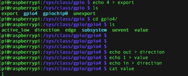
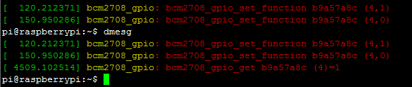
9.烧录到树莓派实验一下
(烧到树莓派的时候要把内核和编译出来的modules全部都拷贝覆盖到树莓派)
最后给一个内核编译的脚本
#!/bin/sh

PWD=`pwd`
export PATH=${PWD}/../tools/arm-bcm2708/gcc-linaro-arm-linux-gnueabihf-raspbian-x64/bin:$PATH

#make ARCH=arm CROSS_COMPILE=arm-linux-gnueabihf- bcm2709_defconfig

make ARCH=arm CROSS_COMPILE=arm-linux-gnueabihf- || exit 1
make ARCH=arm CROSS_COMPILE=arm-linux-gnueabihf- modules || exit 1

rm -rf _install*

make ARCH=arm CROSS_COMPILE=arm-linux-gnueabihf- install INSTALL_PATH=$PWD/_install
make ARCH=arm CROSS_COMPILE=arm-linux-gnueabihf- modules_install INSTALL_MOD_PATH=$PWD/_install

cp arch/arm/boot/Image _install/
cp ../RaspberryKernel/script/install.sh _install/

tar -czf _install.tar.gz _install/