OpenRisc-24-ORPSoC boot过程分析
引言
之前做了很多工作,能起orpmon,能起linux,能run helloworld。但是这些都可以说是空中楼阁,如果不把CPU的启动过程搞明白,总感觉心里没底似的。所以本小节就看一下ORPSoC在最初上电之后做的一些工作,与大部分介绍启动代码的流程的角度有所不同。
Note:并不讨论上电timing等内容,直接从fetch开始。
1,从哪里取第一条指令
从or1200_defines.v里面可以看到PC的初值,这个是由硬件决定的。这个文件的目录和内容如下图:
分析:
第一条取值的地址:0xf0000100
这个地址有两个含义:
1>第一条指令存放的wishbone slave设备的地址是0xf
2>第一条指令存放的wishbone slave设备的内部地址是0x100
此外,这个地址对应的模块,必须在掉电时数据不能丢失。比如flash,rom等。
2,第一条指令 保存在哪呢
既然已经知道wishbone的slave地址,那么只要找到这个地址对应的模块即可:
在orpsoc-params.v里面:
分析:
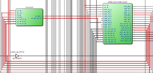
1>这个模块应该挂在arbiter_ibus(指令总线)上,找找看,可以看到指令总线上一共只有两个slave:slave0是rom,slave1是ddr1(sdram):
sdram掉电丢失,那第一条指令一定放在rom0里面:
指令总线上的sdram:
指令总线上的rom0:
2>为了进一步确定,我们查看rom0的wishbone地址,可以看到rom0,这个wishbone slave模块的地址是0xf,如下图:
3,第一条指令是什么呢
既然已经知道第一条指令的存放模块和模块内部的地址,找到rom0的rtl模块,看看吧:
分析:
里面有一个包含文件bootrom.v:就是指令:
bootrom.v内容:
4,启动代码的反汇编
上面我们找到了启动代码的存放地方,但是都是十六进制的,共40条指令,一般人看不懂,所以我就手动反汇编了一下:
之前没有手动反汇编过,这次体验了一下,40条指令,竟然用了2个多小时。
详细反汇编过程和结果,以及分析结果,我已上传:
http://download.csdn.net/detail/rill_zhen/5349541
步骤:
第一步:先将十六进制代码转成二进制。
第二步:将二进制与Architecture Manual中的指令集对照,找到对应的指令类型。
第三步:逐个分析每个指令的含义,得到其汇编指令。
如下:
最终结果如下:
/*
* file:rom.S
* rill create 2013-04-26
* [email protected]
*
*/

l.movhi r0,0x0  //boot init,rill add 130509
l.movhi r1, 0x0
l.movhi r4, 0xb000


l.ori r2, r0, 0x51  //spi init,rill add 130509
l.sb 0x0(r4),r2
l.sb 0x4(r4),r0
l.ori r6, r0, 0x1
l.sb 0x4(r4),r6
l.jal 0x18
l.ori r3, r0, 0x3
l.jal 0x16
l.ori r3, r0, 0xc
l.jal 0x14
l.ori r3, r0, 0x0
l.jal 0x12
l.ori r3, r0, 0x0
l.movhi r6, 0x0
l.movhi r7, 0xffff


l.jal 0xe  //copy,rill add 130509
l.add r8,r6,r0
l.sb 0x0(r8),r3
l.addi r6,r6,0x1
l.sfeqi r6,0x4
l.bf 0x7
l.sfeq r6,r7
l.bnf 0x3fffff9
l.nop


l.ori r1, r1, 0x100 //reset ,rill add 130509
l.jr r1
l.sb 0x4(r4),r0

l.j 0x3fffff4  //stor word,rill add 130509
l.lwz r7,0x0(r1)


l.sb 0x2(r4),r3  //spi_xfer,rill add 130509
l.ori r3, r0, 0x1

l.andi r3,r3,0x1  //spi_xfer_poll,rill add 130509
l.sfeqi r3,0x1
l.bf 0x3fffffe
l.lbz r3,0x1(r4)
l.jr r9
l.lbz r3,r4,0x2
5,疑问
经过上面的折腾,之前的空中楼阁总算离地面近了不少。
上面的过程看似很好,但是有一点疑问:
既然第一条指令的地址是0xf0000100,0xf这个地址对应rom0,这没错,
但是rom0的内容在0x100这个地方没有东西啊,它只有40条指令啊,也就是说rom.v里面的那个“case (wb_adr_i)”语句是走default的,也就是说第一条指令是取不到!
我查了一下flashrom,例化的orpsoc_flashROM模块,里面有devboard_flashROM.mem文件,但是ORPSoC这个project并没有用它,如下图:
另外:case (wb_adr_i)后面的地址应该是0xf开头的啊。怎么是从0开始的呢,即使是从0开始,也应该是0,4,8,c。。。。间隔为4啊。
还有,两个boot地址:OR1200_BOOT_PCREG_DEFAULT 和 OR1200_BOOT_ADR既然可以根据一个相互计算出另外一个(OR1200_BOOT_PCREG_DEFAULT should be ((OR1200_BOOT_ADR-4)>>2))。为什么还要两个地址呢。
怎么回事?我错在哪里了呢?
6,疑问的解决
1>rom的wishbone地址的问题:
经过查看genpc模块,if模块,immu模块,ic模块,biu模块,都没有发现问题,最后不经意间发现如下问题,疑惑荡然无存。
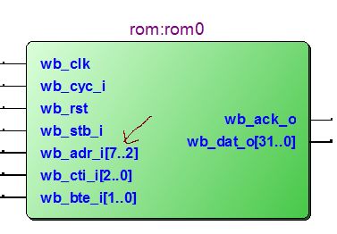
经过查找发现case中的wb_adr_i,只用了[7:2] 6个bit,如下图,需要注意的是本地的参数经过了重定义:
本地参数:
重定义参数:
rom0的指令总线上对应的地址:
从上面可以才看出:0xf0000100(32‘b1111_0000_0000_0000_0000_0001_0000_0000)这个boot地址只用了[7:2] 共6位。
地址的间隔也是0,1,2,3,4,。。。。间隔为1。当然也决定的启动代码的大小不能超过2的6次方(64条),这个rom只用了40条,是符合要求的。
2>两个启动地址的转换问题
看完下面的代码,clear了:
7,总结
通过上面的努力,我们对ORPSoC的最初的启动过程有了一个直观的清晰的了解了。
附录:
1, for more information:
http://opencores.org/or1k/ORPSoC_RTL_simulation_debugging#bootrom
2,其实可以直接查看bootrom的源码:发现和我手动反汇编的结果一致!
soc-design/orpsocv2/sw/bootrom
通过这个目录下的makefile文件可以看出,将bootrom.S转换成bootrom.v的过程。其中有代码的拷贝,但是被拷贝的代码从何而来呢,请参考:
http://blog.csdn.net/rill_zhen/article/details/9045837
3,文件详细内容如下:
board.h:
#ifndef _BOARD_H_
#define _BOARD_H_

#define IN_CLK  	      50000000 // Hz
//#define IN_CLK  	      32000000 // Hz
//#define IN_CLK  	      30000000 // HZ
//#define IN_CLK  	      24000000 // HZ
//#define IN_CLK  	      20000000 // HZ
//#define IN_CLK  	      18000000 // HZ
//#define IN_CLK  	      16000000 // HZ

//
// ROM bootloader
//
// Uncomment the appropriate bootloader define. This will effect the bootrom.S
// file, which is compiled and converted into Verilog for inclusion at
// synthesis time. See bootloader/bootloader.S for details on each option.
#ifndef PRELOAD_RAM
#define BOOTROM_SPI_FLASH
//#define BOOTROM_GOTO_RESET
//#define BOOTROM_LOOP_AT_ZERO
//#define BOOTROM_LOOP_IN_ROM
#define BOOTROM_ADDR_BYTE2 0x0c
#define BOOTROM_ADDR_BYTE1 0x00
#define BOOTROM_ADDR_BYTE0 0x00
#else
#define BOOTROM_GOTO_RESET
#endif

//
// Defines for each core (memory map base, OR1200 interrupt line number, etc.)
//
#define SDRAM_BASE                 0x0
//#define MT48LC32M16A2 // 64MB SDRAM part
#define MT48LC16M16A2 // 32MB SDRAM part
//#define MT48LC4M16A2 // 8MB SDRAM part

#define FLASHROM_BASE       0xcf000000
#define FLASHROM_SIZE            0x100

#define GPIO_0_BASE         0x91000000

#define UART0_BASE  	    0x90000000
#define UART0_IRQ                    2
#define UART0_BAUD_RATE 	115200

#define UART1_BASE  	    0x93000000
#define UART1_IRQ                    3
#define UART1_BAUD_RATE 	115200

#define UART2_BASE  	    0x94000000
#define UART2_IRQ                    5
#define UART2_BAUD_RATE 	115200

#define SPI0_BASE           0xb0000000
#define SPI0_IRQ                     6

#define SPI1_BASE           0xb1000000
#define SPI1_IRQ                     7

#define SPI2_BASE           0xb2000000
#define SPI2_IRQ                     8

#define I2C_0_BASE          0xa0000000
#define I2C_0_IRQ                   10

#define I2C_1_BASE          0xa1000000
#define I2C_1_IRQ                   11

#define I2C_2_BASE          0xa2000000
#define I2C_2_IRQ                   12

#define I2C_3_BASE          0xa3000000
#define I2C_3_IRQ                   13

#define USB0_BASE            0x9c000000
#define USB0_HOST_IRQ                20
#define USB0_SLAVE_IRQ               21

#define USB1_BASE            0x9d000000
#define USB1_HOST_IRQ                22
#define USB1_SLAVE_IRQ               23

#define ETH0_BASE            0x92000000
#define ETH0_IRQ                      4

#define ETH_MACADDR0	           0x00
#define ETH_MACADDR1	           0x12
#define ETH_MACADDR2  	           0x34
#define ETH_MACADDR3	           0x56
#define ETH_MACADDR4  	           0x78
#define ETH_MACADDR5	           0x9a


//
// OR1200 tick timer period define
//
#define TICKS_PER_SEC   100

//
// UART driver initialisation
//
#define UART_NUM_CORES 3

#define UART_BASE_ADDRESSES_CSV						\
	UART0_BASE, UART2_BASE, UART2_BASE

#define UART_BAUD_RATES_CSV						\
	UART0_BAUD_RATE, UART1_BAUD_RATE, UART1_BAUD_RATE

//
// i2c_master_slave core driver configuration
//

#define I2C_MASTER_SLAVE_NUM_CORES 4

#define I2C_MASTER_SLAVE_BASE_ADDRESSES_CSV		\
	I2C_0_BASE, I2C_1_BASE, I2C_2_BASE,I2C_3_BASE


#endif
bootrom.S:
//////////////////////////////////////////////////////////////////////
///                                                               ////
/// bootrom                                                       ////
///                                                               ////
/// Assembly programs to be embedded inside system to aid boot    ////
///                                                               ////
/// Julius Baxter, [email protected]                           ////
///                                                               ////
//////////////////////////////////////////////////////////////////////
////                                                              ////
//// Copyright (C) 2009, 2010 Authors and OPENCORES.ORG           ////
////                                                              ////
//// This source file may be used and distributed without         ////
//// restriction provided that this copyright statement is not    ////
//// removed from the file and that any derivative work contains  ////
//// the original copyright notice and the associated disclaimer. ////
////                                                              ////
//// This source file is free software; you can redistribute it   ////
//// and/or modify it under the terms of the GNU Lesser General   ////
//// Public License as published by the Free Software Foundation; ////
//// either version 2.1 of the License, or (at your option) any   ////
//// later version.                                               ////
////                                                              ////
//// This source is distributed in the hope that it will be       ////
//// useful, but WITHOUT ANY WARRANTY; without even the implied   ////
//// warranty of MERCHANTABILITY or FITNESS FOR A PARTICULAR      ////
//// PURPOSE.  See the GNU Lesser General Public License for more ////
//// details.                                                     ////
////                                                              ////
//// You should have received a copy of the GNU Lesser General    ////
//// Public License along with this source; if not, download it   ////
//// from http://www.opencores.org/lgpl.shtml                     ////
////                                                              ////
//////////////////////////////////////////////////////////////////////

// Defines for which bootrom app to use are in board.h - TODO: use the
// processed orspoc-defines.v file for this define. It makes more sense
// as this software ends up as gates.

#include "board.h"

#ifdef BOOTROM_SPI_FLASH

	/* Assembly program to go into the boot ROM */
	/* For use with simple_spi SPI master core and standard SPI flash
	   interface-compatible parts (ST M25P16 for example.)*/
	/* Currently just loads a program from SPI flash into RAM */
	/* Assuming address at RAM_LOAD_BASE gets clobbered, we need
	   a byte writable address somewhere!*/

#define SPI_BASE SPI0_BASE
/* simple_spi driver */
#define SPI_SPCR 0x0
#define SPI_SPSR 0x1
#define SPI_SPDR 0x2
#define SPI_SPER 0x3
#define SPI_SPSS 0x4

#define SPI_SPCR_XFER_GO 0x51
#define SPI_SPSS_INIT 0x1
#define SPI_SPSR_RX_CHECK 0x01 /* Check bit 0 is cleared, fifo !empty*/

#define RAM_LOAD_BASE SDRAM_BASE
#define RESET_ADDR 0x100

boot_init:
	l.movhi r0, 0
	l.movhi r1, RAM_LOAD_BASE
	l.movhi r4, hi(SPI_BASE)

spi_init:
	l.ori 	r2, r0, SPI_SPCR_XFER_GO /* Setup SPCR with enable bit set */
	l.sb 	SPI_SPCR(r4), r2
	l.sb  	SPI_SPSS(r4), r0         /* Clear SPI slave selects */
	l.ori 	r6, r0, SPI_SPSS_INIT
	l.sb  	SPI_SPSS(r4), r6         /* Set appropriate slave select */
	l.jal	spi_xfer
	l.ori 	r3, r0, 0x3              /* READ command opcode for SPI device*/
	l.jal 	spi_xfer
#ifdef BOOTROM_ADDR_BYTE2
	l.ori 	r3, r0, BOOTROM_ADDR_BYTE2 /* Use addr if defined. MSB first */
#else
	l.or 	r3, r0, r0
#endif
	l.jal 	spi_xfer
#ifdef BOOTROM_ADDR_BYTE1
	l.ori 	r3, r0, BOOTROM_ADDR_BYTE1
#else
	l.or 	r3, r0, r0
#endif
	l.jal 	spi_xfer
#ifdef BOOTROM_ADDR_BYTE0
	l.ori 	r3, r0, BOOTROM_ADDR_BYTE0
#else
	l.or 	r3, r0, r0
#endif
	l.movhi r6, 0
	l.movhi r7, 0xffff

copy:
	l.jal 	spi_xfer         /* Read a byte into r3 */
	l.add 	r8, r1, r6       /* Calculate store address */
	l.sb 	0(r8), r3        /* Write byte to memory */
	l.addi 	r6, r6, 1        /* Increment counter */
	l.sfeqi r6, 0x4          /* Is this the first word ?*/
	l.bf 	store_sizeword   /* put sizeword in the register */
	l.sfeq 	r6, r7           /* Check if we've finished loading the words */
	l.bnf 	copy             /* Continue copying if not last word */
	l.nop

goto_reset:
	l.ori 	r1, r1, RESET_ADDR
	l.jr 	r1
	l.sb  	SPI_SPSS(r4), r0 /* Clear SPI slave selects */

store_sizeword:
#ifdef SPI_RETRY_IF_INSANE_SIZEWORD
	l.lwz 	r7, 0(r1)        /* Size word is in first word of SDRAM */
	l.srli	r10, r7, 16	 /* Chop the sizeword we read in half */
	l.sfgtui r10, 0x0200	 /* It's unlikely we'll ever load > 32MB */
	l.bf	boot_init
	l.nop
	l.j 	copy
	l.nop

#else
	l.j 	copy
	l.lwz 	r7, 0(r1)         /* Size word is in first word of SDRAM */
#endif

spi_xfer:
	l.sb 	SPI_SPDR(r4), r3  /* Dummy write what's in r3 */
	l.ori 	r3, r0, SPI_SPSR_RX_CHECK /* r3 = , ensure loop just once */
spi_xfer_poll:
	l.andi 	r3, r3, SPI_SPSR_RX_CHECK /* AND read fifo bit empty */
	l.sfeqi r3, SPI_SPSR_RX_CHECK    /* is bit set? ... */
	l.bf 	spi_xfer_poll     /* ... if so, rxfifo empty, keep polling */
	l.lbz 	r3, SPI_SPSR(r4) /* Read SPSR */
	l.jr 	r9
	l.lbz 	r3, SPI_SPDR(r4) /* Get data byte */


#endif

#ifdef BOOTROM_GOTO_RESET
	/* Jump to reset vector in the SDRAM */
	l.movhi r0, 0
	l.movhi r4, SDRAM_BASE
	l.ori 	r4, r4, 0x100
	l.jr 	r4
	l.nop

#endif

#ifdef BOOTROM_LOOP_AT_ZERO

	/* Don't load app via SPI, instead just put an infinite loop into bottom
	of memory and jump there.
	*/
	l.movhi r0, 0
	l.movhi r4, SDRAM_BASE
	l.sw 	0x0(r4), r0
	l.movhi r5, hi(0x15000001) /* A l.nop 1 so sim exits if this enabled */
	l.ori 	r5, r5, lo(0x15000001)
	l.sw 	0x4(r4), r5
	l.sw 	0x8(r4), r5
	l.sw 	0xc(r4), r5
	l.jr 	r4
	l.nop


#endif

#ifdef BOOTROM_LOOP_IN_ROM

	/* Don't load app via SPI, instead just put an infinite loop into bottom
	of memory and jump there.
	*/
	l.movhi r0, 0
	l.nop 	0x1
	l.j 	0
	l.nop
	l.nop
#endif
bootrom.v:可以比较这个目录下的文件和soc-design\orpsocv2\boards\altera\ordb2a-ep4ce22\rtl\verilog\include目录下的文件创建时间,相同。
0 : wb_dat_o <=  32'h18000000;
1 : wb_dat_o <=  32'h18200000;
2 : wb_dat_o <=  32'h1880b000;
3 : wb_dat_o <=  32'ha8400051;
4 : wb_dat_o <=  32'hd8041000;
5 : wb_dat_o <=  32'hd8040004;
6 : wb_dat_o <=  32'ha8c00001;
7 : wb_dat_o <=  32'hd8043004;
8 : wb_dat_o <=  32'h04000018;
9 : wb_dat_o <=  32'ha8600003;
10 : wb_dat_o <=  32'h04000016;
11 : wb_dat_o <=  32'ha860000c;
12 : wb_dat_o <=  32'h04000014;
13 : wb_dat_o <=  32'ha8600000;
14 : wb_dat_o <=  32'h04000012;
15 : wb_dat_o <=  32'ha8600000;
16 : wb_dat_o <=  32'h18c00000;
17 : wb_dat_o <=  32'h18e0ffff;
18 : wb_dat_o <=  32'h0400000e;
19 : wb_dat_o <=  32'he1013000;
20 : wb_dat_o <=  32'hd8081800;
21 : wb_dat_o <=  32'h9cc60001;
22 : wb_dat_o <=  32'hbc060004;
23 : wb_dat_o <=  32'h10000007;
24 : wb_dat_o <=  32'he4063800;
25 : wb_dat_o <=  32'h0ffffff9;
26 : wb_dat_o <=  32'h15000000;
27 : wb_dat_o <=  32'ha8210100;
28 : wb_dat_o <=  32'h44000800;
29 : wb_dat_o <=  32'hd8040004;
30 : wb_dat_o <=  32'h03fffff4;
31 : wb_dat_o <=  32'h84e10000;
32 : wb_dat_o <=  32'hd8041802;
33 : wb_dat_o <=  32'ha8600001;
34 : wb_dat_o <=  32'ha4630001;
35 : wb_dat_o <=  32'hbc030001;
36 : wb_dat_o <=  32'h13fffffe;
37 : wb_dat_o <=  32'h8c640001;
38 : wb_dat_o <=  32'h44004800;
39 : wb_dat_o <=  32'h8c640002;
makefile:从中可以看到bootrom.S的编译,转换过程,及用到的工具。
# Makefile for bootROM Verilog
SW_ROOT=..
include $(SW_ROOT)/Makefile.inc

# Whenever PRELOAD_RAM is defined on command line, we probably want the bootrom
# to be jumping to reset instead of doing a full boot preload.
ifeq ($(PRELOAD_RAM),1)
OR32_CFLAGS += -DPRELOAD_RAM
endif

all: bootrom.v

%.v: %.bin $(SW_ROOT)/utils/bin2vlogarray
	$(Q)$(SW_ROOT)/utils/bin2vlogarray < $< > $@

%.dis: %.o
	$(Q)$(OR32_OBJDUMP) -d $< > $@

%.bin: %.o
	$(Q)$(OR32_OBJCOPY) -O binary $< $@

$(SW_ROOT)/utils/bin2vlogarray:
	$(Q)$(MAKE) -C $(SW_ROOT)/utils bin2vlogarray

clean:
	$(Q)rm -f *.o *.bin *.hex *.in *.dis *.v
后记
合抱之木,生于毫末;九层之台,起于垒土;千里之行,始于足下。


