凸凹纹理
凹凸纹理映射是一种纹理混合方法,它可以创建三维物体复杂的纹理外观表面。普通的纹理映射只能模拟比较平滑的三维物体表面,难以显示表面高低起伏、凹凸不平的效果。凹凸纹理映射能够通过一张表示物体表面凹凸程度的高度图(称为凹凸纹理),对另一张表示物体表面环境映射的纹理图的纹理坐标进行相应的干扰,经过干扰的纹理坐标将应用于环境映射,从而产生凹凸不平的显示效果。凹凸纹理映射通常由三张纹理映射图组成,第一张纹理图表示物体表面原始纹理颜色,第二张凹凸纹理图表示物体表面凹凸的高度起伏值,用来对下一张环境纹理图坐标进行干扰,第三张纹理图表示周围镜面反射或漫反射光照的环境光照映射图。凹凸纹理映射的纹理映射流程如下图所示:
检查硬件设备
在使用凹凸纹理映射之前,应查询当前的Direct3D设备是否支持D3DTEXOPCAPS_BUMPENVMAP或D3DTEXOPCAPS_BUMPENVMAPLUMINANCE多层纹理混合,以及当前设备是否支持3层纹理映射。
BOOL SupportsBumpMapping()
{
    D3DCAPS9 d3dCaps;
    d3dDevice->GetDeviceCaps( &d3dCaps );
    // Does this device support the two bump mapping blend operations?
    if ( 0 == d3dCaps.TextureOpCaps & ( D3DTEXOPCAPS_BUMPENVMAP | D3DTEXOPCAPS_BUMPENVMAPLUMINANCE ))
        return FALSE;
    // Does this device support up to three blending stages?
    if( d3dCaps.MaxTextureBlendStages < 3 )
        return FALSE;
    return TRUE;
}
如果当前硬件不支持上面的任何一项,程序框架会自动转而使用参考设备。
凹凸纹理生成
Direct3D的凹凸纹理被用来表示物体表面相邻像素的高度差,它的每个纹理元素由表示水平相邻像素高度差的Du、表示垂直相邻像素高度差的Dv以及表示该点亮度的L组成(某些凹凸纹理像素格式可以不包含L)。下表列出了Direct3D支持的凹凸纹理像素格式:
| 凹凸纹理像素格式 | 说明 |
| D3DFMT_V8U8 | 每个像素由16位整数表示,分别由8位整数表示Du和Dv |
| D3DFMT_L6V5U5 | 每个像素由16位整数表示,6位整数表示L,分别由5位整数表示Du和Dv |
| D3DFMT_X8L8V8U8 | 每个像素由32位整数表示,包括8位保留位、8位L、8位Du、8位Dv |
| D3DFMT_V16U16 | 每个像素由32位整数表示,分别由16位整数表示Du和Dv |
| D3DFMT_Q8W8V8U8 | 每个像素由32位整数表示,分别由8位整数表示Q、W、V、U |
| D3DFMT_CxV8U8 | 压缩像素格式,每个像素由16位整数表示,即8位Du和8位Dv,另外C = sqrt(1 - Du2 - Dv2 ) |
通常情况下,可以载入一张表示物体表面图像高度的纹理图,通过计算高度图水平相邻和垂直相邻元素的高度差来生成凹凸纹理,也可以通过程序生成凹凸纹理,这里根据纹理图来生成凹凸纹理,代码如下:
//--------------------------------------------------------------------------------------
// Create bump texture from height map texture.
//--------------------------------------------------------------------------------------
HRESULT CreateBumpTexture(IDirect3DDevice9* device)
{
	HRESULT hr;
	D3DSURFACE_DESC surface_desc;
	g_height_map_texture->GetLevelDesc(0, &surface_desc);
	V_RETURN(device->CreateTexture(surface_desc.Width, surface_desc.Height, 1, 0, D3DFMT_X8L8V8U8, D3DPOOL_MANAGED,
								   &g_bump_map_texture, NULL));
	D3DLOCKED_RECT locked_rect;
	g_height_map_texture->LockRect(0, &locked_rect, NULL, 0);
	DWORD src_pitch   = (DWORD) locked_rect.Pitch;
	BYTE* src_row_top = (BYTE*) locked_rect.pBits;
	BYTE* src_row_cur = src_row_top;
	BYTE* src_row_bot = src_row_top + src_pitch * (surface_desc.Height - 1);
g_bump_map_texture->LockRect(0, &locked_rect, NULL, 0);
	DWORD dest_pitch   = (DWORD) locked_rect.Pitch;
	BYTE* dest_row_top = (BYTE*) locked_rect.pBits;
	BYTE* dest_row_cur = dest_row_top;
	// iterate through all lines
	for(DWORD y = 0; y < surface_desc.Height; y++)
	{
		BYTE* src_pixel_cur;
		BYTE* src_pixel_up;
		BYTE* src_pixel_below;
		BYTE* dest_pixel;
src_pixel_cur = src_row_cur;
		if(y == 0)
			src_pixel_up = src_row_bot;
		else
			src_pixel_up = src_row_cur - src_pitch;
		if(y == surface_desc.Height - 1)
			src_pixel_below = src_row_top;
		else
			src_pixel_below = src_row_cur + src_pitch;
dest_pixel = dest_row_cur;
		// iterate through all columns in current line
		for(DWORD x = 0; x < surface_desc.Width; x++)
		{
			BYTE src_pixel_left, src_pixel_right;
			if(x == 0)
				src_pixel_left = *(src_row_cur + (surface_desc.Width - 4));
			else
				src_pixel_left = *(src_pixel_cur - 4);
			if(x == surface_desc.Width - 1)
				src_pixel_right = *src_row_cur;
			else
				src_pixel_right = *(src_pixel_cur + 4);
			BYTE du = BYTE(src_pixel_left - src_pixel_right);
			BYTE dv = BYTE(src_pixel_up   - src_pixel_below);
			// the luminance bump value
			BYTE u_lumi = (*src_pixel_cur > 1) ? 63 : 127;
			*dest_pixel++ = du;
			*dest_pixel++ = dv;
			*dest_pixel++ = u_lumi;
			*dest_pixel++ = 0;
			// move one pixel to the right
			src_pixel_cur   += 4;
			src_pixel_up     += 4;
			src_pixel_below += 4;
		}
		// move to the next line
		src_row_cur  += src_pitch;
		dest_row_cur += dest_pitch;
	}
	g_bump_map_texture->UnlockRect(0);
	g_height_map_texture->UnlockRect(0);
	return S_OK;
}
凹凸纹理设置
凹凸纹理映射通常使用3层纹理:物体原始纹理、由原始纹理高度图生成的凹凸纹理、环境纹理,对应于多层纹理混合的0、1、2层。指定当前纹理层状态为D3DTOP_BUMPENVMAP或D3DTOP_BUMPENVMAPLUMINANCE可设置当前纹理层为凹凸纹理,例如:
pd3dDevice->SetTexture(1, g_bump_map_texture);
pd3dDevice->SetTextureStageState(1, D3DTSS_COLOROP,		   D3DTOP_BUMPENVMAP);
或
pd3dDevice->SetTexture(1, g_bump_map_texture);
pd3dDevice->SetTextureStageState(1, D3DTSS_COLOROP,		   D3DTOP_BUMPENVMAPLUMINANCE);
纹理状态D3DTOP_BUMPENVMAP和D3DTOP_BUMPENVMAPLUMINANCE表示两种不同的凹凸纹理映射方法。纹理状态D3DTOP_BUMPENVMAPLUMINANCE表示在凹凸纹理中包含凹凸纹理亮度值L,L将与下一纹理层的纹理颜色相乘作为最后输出的纹理颜色。纹理状态D3DTOP_BUMPENVMAP默认亮度值L为1,即不改变下一纹理层的纹理颜色。
这里分别使用了3层纹理贴图,如下所示:
原始纹理
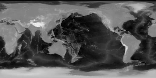
原始纹理高度图
环境纹理贴图
Direct3D可设置凹凸纹理矩阵,对凹凸纹理中的每个纹理元素值(Dv、Du,即对于下一纹理层中的每个纹理坐标的扰动值)进行坐标变换:
Du' = Du * M00 + Dv * M10
Dv' = Dv * M01 + Dv * M11
凹凸纹理的每个纹理元素Dv、Du与一个2 x 2的凹凸矩阵相乘,其结果Dv、Du对下一纹理层中的每个纹理元素的纹理坐标产生该数值代表的坐标扰动。2 x 2的凹凸矩阵值可由函数IDirect3DDevice9::SetTextureStageState()设置,将它的第一个参数设置为纹理层序号,第二个参数设置为D3DTSS_BUMPENVMAT00或D3DTSS_BUMPENVMAT01或D3DTSS_BUMPENVMAT10或D3DTSS_BUMPENVMAT11,分别表示凹凸矩阵的4个矩阵元素,第三个参数设置为该矩阵元素的值。纹理坐标扰动Dv、Du或Dv'、Du'的范围介于-1 ~ +1之间。
如果使用D3DTOP_BUMPENVMAPLUMINANCE计算凹凸纹理,Direct3D将使用下列方程计算凹凸纹理的亮度值L'(L'为0~255的整数,它将被用来与下一纹理层的颜色相乘,作为最后输出的纹理颜色值)。
L' = L * S + O
其中,L为凹凸纹理元素中的亮度L值,比例系数S和偏移系数O可改变最终的亮度值。S和O可由函数IDirect3DDevice9::SetTexureStageState()设置,将它的第一个参数设置为纹理层序号,第二个参数设置为D3DTSS_BUMPENVLSCALE或D3DTSS_BUMPENVLOFFSET,分别表示凹凸纹理映射的比例系数S和偏移系数O,将第三个参数设置为相应的系数值。
设置凹凸纹理状态的代码如下所示:
// set texture color blend method for stage 0 (base texture)
pd3dDevice->SetTextureStageState(0, D3DTSS_COLORARG1, D3DTA_TEXTURE);
pd3dDevice->SetTextureStageState(0, D3DTSS_COLOROP, D3DTOP_SELECTARG1);
pd3dDevice->SetSamplerState(0, D3DSAMP_MAGFILTER, D3DTEXF_LINEAR);
pd3dDevice->SetSamplerState(0, D3DSAMP_MINFILTER, D3DTEXF_LINEAR);
// set texture color blend method for stage 1 (bump map texture)
pd3dDevice->SetTexture(1, g_bump_map_texture);
pd3dDevice->SetTextureStageState(1, D3DTSS_TEXCOORDINDEX, 0);
pd3dDevice->SetTextureStageState(1, D3DTSS_COLOROP, D3DTOP_BUMPENVMAPLUMINANCE);
pd3dDevice->SetTextureStageState(1, D3DTSS_COLORARG1, D3DTA_TEXTURE);
pd3dDevice->SetTextureStageState(1, D3DTSS_COLORARG2, D3DTA_CURRENT);
pd3dDevice->SetTextureStageState(1, D3DTSS_BUMPENVMAT00, F2DW(0.8f));
pd3dDevice->SetTextureStageState(1, D3DTSS_BUMPENVMAT01, F2DW(0.0f));
pd3dDevice->SetTextureStageState(1, D3DTSS_BUMPENVMAT10, F2DW(0.0f));
pd3dDevice->SetTextureStageState(1, D3DTSS_BUMPENVMAT11, F2DW(0.8f));
pd3dDevice->SetTextureStageState(1, D3DTSS_BUMPENVLSCALE, F2DW(4.0f));
pd3dDevice->SetTextureStageState(1, D3DTSS_BUMPENVLOFFSET, F2DW(0.0f));
pd3dDevice->SetSamplerState(1, D3DSAMP_MAGFILTER, D3DTEXF_LINEAR);
pd3dDevice->SetSamplerState(1, D3DSAMP_MINFILTER, D3DTEXF_LINEAR);
// set texture color blend method for stage 2 (environment map texture)
D3DXMATRIX mat;
mat._11 = 0.5f; mat._12 = 0.0f; mat._13 = 0.0f; mat._14 = 0.0f;
mat._21 = 0.0f; mat._22 = -0.5f; mat._23 = 0.0f; mat._24 = 0.0f;
mat._31 = 0.0f; mat._32 = 0.0f; mat._33 = 1.0f; mat._34 = 0.0f;
mat._41 = 0.5f; mat._42 = 0.5f; mat._43 = 0.0f; mat._44 = 1.0f;
pd3dDevice->SetTransform(D3DTS_TEXTURE2, &mat);
pd3dDevice->SetTexture(2, g_env_map_texture);
pd3dDevice->SetTextureStageState(2, D3DTSS_TEXTURETRANSFORMFLAGS, D3DTTFF_COUNT2);
pd3dDevice->SetTextureStageState(2, D3DTSS_TEXCOORDINDEX, D3DTSS_TCI_SPHEREMAP);
pd3dDevice->SetTextureStageState(2, D3DTSS_COLORARG1, D3DTA_TEXTURE);
pd3dDevice->SetTextureStageState(2, D3DTSS_COLORARG2, D3DTA_CURRENT);
pd3dDevice->SetTextureStageState(2, D3DTSS_COLOROP, D3DTOP_ADD);
pd3dDevice->SetSamplerState(2, D3DSAMP_MAGFILTER, D3DTEXF_LINEAR);
pd3dDevice->SetSamplerState(2, D3DSAMP_MINFILTER, D3DTEXF_LINEAR);
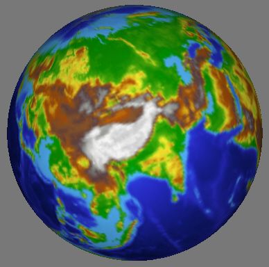
原始纹理图
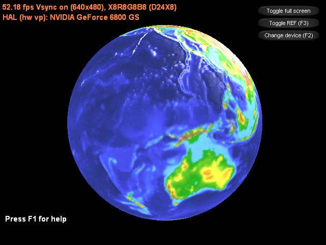
经过凹凸纹理映射后
主程序:
#include " resource.h "
#pragma warning(disable : 4127 4995 4996 )
#define release_com(p) do { if(p) { (p)->Release(); (p) = NULL; } } while(0)
#define IDC_TOGGLE_FULLSCREEN 1
#define IDC_TOGGLE_REF 2
#define IDC_CHANGE_DEVICE 3
const D3DXCOLOR FONT_COLOR( 1.0f , 0.5f , 0.25f , 1.0f );
ID3DXFont * g_font;
ID3DXSprite * g_text_sprite;
bool g_show_help;
CDXUTDialogResourceManager g_dlg_resource_manager;
CD3DSettingsDlg g_settings_dlg;
CDXUTDialog g_button_dlg;
ID3DXMesh * g_mesh;
D3DMATERIAL9 * g_mesh_materials;
IDirect3DTexture9 ** g_mesh_textures;
DWORD g_num_materials;
IDirect3DTexture9 * g_env_map_texture;
IDirect3DTexture9 * g_height_map_texture;
IDirect3DTexture9 * g_bump_map_texture;
inline DWORD F2DW( float f) { return * ((DWORD * ) & f); }
// --------------------------------------------------------------------------------------
// Rejects any devices that aren't acceptable by returning false
// --------------------------------------------------------------------------------------
bool CALLBACK IsDeviceAcceptable( D3DCAPS9 * pCaps, D3DFORMAT AdapterFormat,
D3DFORMAT BackBufferFormat, bool bWindowed, void * pUserContext )
{
// Typically want to skip backbuffer formats that don't support alpha blending
IDirect3D9 * pD3D = DXUTGetD3DObject();
if ( FAILED( pD3D -> CheckDeviceFormat( pCaps -> AdapterOrdinal, pCaps -> DeviceType, AdapterFormat,
D3DUSAGE_QUERY_POSTPIXELSHADER_BLENDING, D3DRTYPE_TEXTURE, BackBufferFormat ) ) )
return false ;
// check whether device support bump textue mapping
if ((pCaps -> TextureOpCaps & (D3DTEXOPCAPS_BUMPENVMAP | D3DTEXOPCAPS_BUMPENVMAPLUMINANCE)) == 0 )
return false ;
// check whether device support 3 level texture stage blend
if (pCaps -> MaxTextureBlendStages < 3 )
return false ;
return true ;
}
// --------------------------------------------------------------------------------------
// Before a device is created, modify the device settings as needed.
// --------------------------------------------------------------------------------------
bool CALLBACK ModifyDeviceSettings( DXUTDeviceSettings * pDeviceSettings, const D3DCAPS9 * pCaps, void * pUserContext )
{
// If video card does not support hardware vertex processing, then uses sofaware vertex processing.
if ((pCaps -> DevCaps & D3DDEVCAPS_HWTRANSFORMANDLIGHT) == 0 )
pDeviceSettings -> BehaviorFlags = D3DCREATE_SOFTWARE_VERTEXPROCESSING;
static bool is_first_time = true ;
if (is_first_time)
{
is_first_time = false ;
// if using reference device, then pop a warning message box.
if (pDeviceSettings -> DeviceType == D3DDEVTYPE_REF)
DXUTDisplaySwitchingToREFWarning();
}
return true ;
}
// --------------------------------------------------------------------------------------
// Create bump texture from height map texture.
// --------------------------------------------------------------------------------------
HRESULT CreateBumpTexture(IDirect3DDevice9 * device)
{
HRESULT hr;
D3DSURFACE_DESC surface_desc;
g_height_map_texture -> GetLevelDesc( 0 , & surface_desc);
V_RETURN(device -> CreateTexture(surface_desc.Width, surface_desc.Height, 1 , 0 , D3DFMT_X8L8V8U8, D3DPOOL_MANAGED,
& g_bump_map_texture, NULL));
D3DLOCKED_RECT locked_rect;
g_height_map_texture -> LockRect( 0 , & locked_rect, NULL, 0 );
DWORD src_pitch = (DWORD) locked_rect.Pitch;
BYTE * src_row_top = (BYTE * ) locked_rect.pBits;
BYTE * src_row_cur = src_row_top;
BYTE * src_row_bot = src_row_top + src_pitch * (surface_desc.Height - 1 );
g_bump_map_texture -> LockRect( 0 , & locked_rect, NULL, 0 );
DWORD dest_pitch = (DWORD) locked_rect.Pitch;
BYTE * dest_row_top = (BYTE * ) locked_rect.pBits;
BYTE * dest_row_cur = dest_row_top;
// iterate through all lines
for (DWORD y = 0 ; y < surface_desc.Height; y ++ )
{
BYTE * src_pixel_cur;
BYTE * src_pixel_up;
BYTE * src_pixel_below;
BYTE * dest_pixel;
src_pixel_cur = src_row_cur;
if (y == 0 )
src_pixel_up = src_row_bot;
else
src_pixel_up = src_row_cur - src_pitch;
if (y == surface_desc.Height - 1 )
src_pixel_below = src_row_top;
else
src_pixel_below = src_row_cur + src_pitch;
dest_pixel = dest_row_cur;
// iterate through all columns in current line
for (DWORD x = 0 ; x < surface_desc.Width; x ++ )
{
BYTE src_pixel_left, src_pixel_right;
if (x == 0 )
src_pixel_left = * (src_row_cur + (surface_desc.Width - 4 ));
else
src_pixel_left = * (src_pixel_cur - 4 );
if (x == surface_desc.Width - 1 )
src_pixel_right = * src_row_cur;
else
src_pixel_right = * (src_pixel_cur + 4 );
BYTE du = BYTE(src_pixel_left - src_pixel_right);
BYTE dv = BYTE(src_pixel_up - src_pixel_below);
// the luminance bump value
BYTE u_lumi = ( * src_pixel_cur > 1 ) ? 63 : 127 ;
* dest_pixel ++ = du;
* dest_pixel ++ = dv;
* dest_pixel ++ = u_lumi;
* dest_pixel ++ = 0 ;
// move one pixel to the right
src_pixel_cur += 4 ;
src_pixel_up += 4 ;
src_pixel_below += 4 ;
}
// move to the next line
src_row_cur += src_pitch;
dest_row_cur += dest_pitch;
}
g_bump_map_texture -> UnlockRect( 0 );
g_height_map_texture -> UnlockRect( 0 );
return S_OK;
}
// --------------------------------------------------------------------------------------
// Remove path from fullname, and convert filename from multibyte to wchar.
// --------------------------------------------------------------------------------------
void RemovePathFromFileName(LPSTR fullname, LPWSTR wfilename)
{
WCHAR wbuf[MAX_PATH] = { 0 };
MultiByteToWideChar(CP_ACP, 0 , fullname, - 1 , wbuf, MAX_PATH);
LPWSTR w_last_back_slash = wcsrchr(wbuf, ' \\ ' );
if (w_last_back_slash)
lstrcpy(wfilename, ++ w_last_back_slash);
else
lstrcpy(wfilename, wbuf);
}
// --------------------------------------------------------------------------------------
// Create any D3DPOOL_MANAGED resources here
// --------------------------------------------------------------------------------------
HRESULT CALLBACK OnCreateDevice( IDirect3DDevice9 * pd3dDevice,
const D3DSURFACE_DESC * pBackBufferSurfaceDesc,
void * pUserContext )
{
HRESULT hr;
V_RETURN(g_dlg_resource_manager.OnCreateDevice(pd3dDevice));
V_RETURN(g_settings_dlg.OnCreateDevice(pd3dDevice));
D3DXCreateFont(pd3dDevice, 18 , 0 , FW_BOLD, 1 , FALSE, DEFAULT_CHARSET, OUT_DEFAULT_PRECIS, DEFAULT_QUALITY,
DEFAULT_PITCH | FF_DONTCARE, L " Arial " , & g_font);
V_RETURN(D3DXCreateTextureFromFile(pd3dDevice, L " HeightMap.bmp " , & g_height_map_texture));
V_RETURN(D3DXCreateTextureFromFile(pd3dDevice, L " EnvMap.bmp " , & g_env_map_texture));
V_RETURN(CreateBumpTexture(pd3dDevice));
ID3DXBuffer * material_buffer;
V_RETURN(D3DXLoadMeshFromXW(L " SphereEarth.x " , D3DXMESH_MANAGED, pd3dDevice, NULL, & material_buffer, NULL,
& g_num_materials, & g_mesh));
D3DXMATERIAL * xmaterials = (D3DXMATERIAL * ) material_buffer -> GetBufferPointer();
g_mesh_materials = new D3DMATERIAL9[g_num_materials];
g_mesh_textures = new IDirect3DTexture9 * [g_num_materials];
for (DWORD i = 0 ; i < g_num_materials; i ++ )
{
g_mesh_materials[i] = xmaterials[i].MatD3D;
// .x file do not save ambient data, so set it here.
g_mesh_materials[i].Ambient = g_mesh_materials[i].Diffuse;
WCHAR wfilename[MAX_PATH];
RemovePathFromFileName(xmaterials[i].pTextureFilename, wfilename);
g_mesh_textures[i] = NULL;
if (xmaterials[i].pTextureFilename != NULL && lstrlen(wfilename) > 0 )
V_RETURN(D3DXCreateTextureFromFile(pd3dDevice, wfilename, & g_mesh_textures[i]));
}
material_buffer -> Release();
return S_OK;
}
// --------------------------------------------------------------------------------------
// Create any D3DPOOL_DEFAULT resources here
// --------------------------------------------------------------------------------------
HRESULT CALLBACK OnResetDevice( IDirect3DDevice9 * pd3dDevice,
const D3DSURFACE_DESC * pBackBufferSurfaceDesc,
void * pUserContext )
{
HRESULT hr;
V_RETURN(g_dlg_resource_manager.OnResetDevice());
V_RETURN(g_settings_dlg.OnResetDevice());
V_RETURN(g_font -> OnResetDevice());
V_RETURN(D3DXCreateSprite(pd3dDevice, & g_text_sprite));
// set dialog position and size
g_button_dlg.SetLocation(pBackBufferSurfaceDesc -> Width - 170 , 0 );
g_button_dlg.SetSize( 170 , 170 );
// setup view matrix
D3DXMATRIX mat_view;
D3DXVECTOR3 eye( 0.0f , - 3.0f , 0.0f );
D3DXVECTOR3 at( 0.0f , 0.0f , 0.0f );
D3DXVECTOR3 up( 0.0f , 0.0f , 1.0f );
D3DXMatrixLookAtLH( & mat_view, & eye, & at, & up);
pd3dDevice -> SetTransform(D3DTS_VIEW, & mat_view);
// set projection matrix
D3DXMATRIX mat_proj;
float aspect = ( float )pBackBufferSurfaceDesc -> Width / pBackBufferSurfaceDesc -> Height;
D3DXMatrixPerspectiveFovLH( & mat_proj, D3DX_PI / 4 , aspect, 1.0f , 1000.0f );
pd3dDevice -> SetTransform(D3DTS_PROJECTION, & mat_proj);
// set texture color blend method for stage 0 (base texture)
pd3dDevice -> SetTextureStageState( 0 , D3DTSS_COLORARG1, D3DTA_TEXTURE);
pd3dDevice -> SetTextureStageState( 0 , D3DTSS_COLOROP, D3DTOP_SELECTARG1);
pd3dDevice -> SetSamplerState( 0 , D3DSAMP_MAGFILTER, D3DTEXF_LINEAR);
pd3dDevice -> SetSamplerState( 0 , D3DSAMP_MINFILTER, D3DTEXF_LINEAR);
// set texture color blend method for stage 1 (bump map texture)
pd3dDevice -> SetTexture( 1 , g_bump_map_texture);
pd3dDevice -> SetTextureStageState( 1 , D3DTSS_TEXCOORDINDEX, 0 );
pd3dDevice -> SetTextureStageState( 1 , D3DTSS_COLOROP, D3DTOP_BUMPENVMAPLUMINANCE);
pd3dDevice -> SetTextureStageState( 1 , D3DTSS_COLORARG1, D3DTA_TEXTURE);
pd3dDevice -> SetTextureStageState( 1 , D3DTSS_COLORARG2, D3DTA_CURRENT);
pd3dDevice -> SetTextureStageState( 1 , D3DTSS_BUMPENVMAT00, F2DW( 0.8f ));
pd3dDevice -> SetTextureStageState( 1 , D3DTSS_BUMPENVMAT01, F2DW( 0.0f ));
pd3dDevice -> SetTextureStageState( 1 , D3DTSS_BUMPENVMAT10, F2DW( 0.0f ));
pd3dDevice -> SetTextureStageState( 1 , D3DTSS_BUMPENVMAT11, F2DW( 0.8f ));
pd3dDevice -> SetTextureStageState( 1 , D3DTSS_BUMPENVLSCALE, F2DW( 4.0f ));
pd3dDevice -> SetTextureStageState( 1 , D3DTSS_BUMPENVLOFFSET, F2DW( 0.0f ));
pd3dDevice -> SetSamplerState( 1 , D3DSAMP_MAGFILTER, D3DTEXF_LINEAR);
pd3dDevice -> SetSamplerState( 1 , D3DSAMP_MINFILTER, D3DTEXF_LINEAR);
// set texture color blend method for stage 2 (environment map texture)
D3DXMATRIX mat;
mat._11 = 0.5f ; mat._12 = 0.0f ; mat._13 = 0.0f ; mat._14 = 0.0f ;
mat._21 = 0.0f ; mat._22 = - 0.5f ; mat._23 = 0.0f ; mat._24 = 0.0f ;
mat._31 = 0.0f ; mat._32 = 0.0f ; mat._33 = 1.0f ; mat._34 = 0.0f ;
mat._41 = 0.5f ; mat._42 = 0.5f ; mat._43 = 0.0f ; mat._44 = 1.0f ;
pd3dDevice -> SetTransform(D3DTS_TEXTURE2, & mat);
pd3dDevice -> SetTexture( 2 , g_env_map_texture);
pd3dDevice -> SetTextureStageState( 2 , D3DTSS_TEXTURETRANSFORMFLAGS, D3DTTFF_COUNT2);
pd3dDevice -> SetTextureStageState( 2 , D3DTSS_TEXCOORDINDEX, D3DTSS_TCI_SPHEREMAP);
pd3dDevice -> SetTextureStageState( 2 , D3DTSS_COLORARG1, D3DTA_TEXTURE);
pd3dDevice -> SetTextureStageState( 2 , D3DTSS_COLORARG2, D3DTA_CURRENT);
pd3dDevice -> SetTextureStageState( 2 , D3DTSS_COLOROP, D3DTOP_ADD);
pd3dDevice -> SetSamplerState( 2 , D3DSAMP_MAGFILTER, D3DTEXF_LINEAR);
pd3dDevice -> SetSamplerState( 2 , D3DSAMP_MINFILTER, D3DTEXF_LINEAR);
return S_OK;
}
// --------------------------------------------------------------------------------------
// Release resources created in the OnResetDevice callback here
// --------------------------------------------------------------------------------------
void CALLBACK OnLostDevice( void * pUserContext )
{
g_dlg_resource_manager.OnLostDevice();
g_settings_dlg.OnLostDevice();
g_font -> OnLostDevice();
release_com(g_text_sprite);
}
// --------------------------------------------------------------------------------------
// Release resources created in the OnCreateDevice callback here
// --------------------------------------------------------------------------------------
void CALLBACK OnDestroyDevice( void * pUserContext )
{
g_dlg_resource_manager.OnDestroyDevice();
g_settings_dlg.OnDestroyDevice();
delete[] g_mesh_materials;
g_mesh_materials = NULL;
if (g_mesh_textures)
{
for (DWORD i = 0 ; i < g_num_materials; i ++ )
release_com(g_mesh_textures[i]);
delete[] g_mesh_textures;
g_mesh_textures = NULL;
}
release_com(g_font);
release_com(g_mesh);
release_com(g_env_map_texture);
release_com(g_height_map_texture);
release_com(g_bump_map_texture);
}
// --------------------------------------------------------------------------------------
// Handle updates to the scene
// --------------------------------------------------------------------------------------
void CALLBACK OnFrameMove( IDirect3DDevice9 * pd3dDevice, double fTime, float fElapsedTime, void * pUserContext )
{
D3DXMATRIX mat_world;
D3DXMatrixRotationZ( & mat_world, timeGetTime() / 1000.0f );
pd3dDevice -> SetTransform(D3DTS_WORLD, & mat_world);
}
// --------------------------------------------------------------------------------------
// Render the helper information
// --------------------------------------------------------------------------------------
void RenderText()
{
CDXUTTextHelper text_helper(g_font, g_text_sprite, 20 );
text_helper.Begin();
// show frame and device states
text_helper.SetInsertionPos( 5 , 5 );
text_helper.SetForegroundColor(FONT_COLOR);
text_helper.DrawTextLine( DXUTGetFrameStats( true ) );
text_helper.DrawTextLine( DXUTGetDeviceStats() );
// show helper information
const D3DSURFACE_DESC * surface_desc = DXUTGetBackBufferSurfaceDesc();
if (g_show_help)
{
text_helper.SetInsertionPos( 10 , surface_desc -> Height - 18 * 5 );
text_helper.SetForegroundColor(FONT_COLOR);
text_helper.DrawTextLine(L " Controls (F1 to hide): " );
text_helper.SetInsertionPos( 40 , surface_desc -> Height - 18 * 4 );
text_helper.DrawTextLine(L " Quit: ESC " );
}
else
{
text_helper.SetInsertionPos( 10 , surface_desc -> Height - 15 * 4 );
text_helper.SetForegroundColor( D3DXCOLOR( 1.0f , 1.0f , 1.0f , 1.0f ) );
text_helper.DrawTextLine(L " Press F1 for help " );
}
text_helper.End();
}
// --------------------------------------------------------------------------------------
// Render the scene
// --------------------------------------------------------------------------------------
void CALLBACK OnFrameRender( IDirect3DDevice9 * pd3dDevice, double fTime, float fElapsedTime, void * pUserContext )
{
HRESULT hr;
if (g_settings_dlg.IsActive())
{
g_settings_dlg.OnRender(fElapsedTime);
return ;
}
// Clear the render target and the zbuffer
V( pd3dDevice -> Clear( 0 , NULL, D3DCLEAR_TARGET | D3DCLEAR_ZBUFFER, D3DCOLOR_ARGB( 0 , 0 , 0 , 0 ), 1.0f , 0 ) );
// Render the scene
if ( SUCCEEDED( pd3dDevice -> BeginScene() ) )
{
for (DWORD i = 0 ; i < g_num_materials; i ++ )
{
pd3dDevice -> SetMaterial( & g_mesh_materials[i]);
pd3dDevice -> SetTexture( 0 , g_mesh_textures[i]);
g_mesh -> DrawSubset(i);
}
RenderText();
V(g_button_dlg.OnRender(fElapsedTime));
V( pd3dDevice -> EndScene() );
}
}
// --------------------------------------------------------------------------------------
// Handle messages to the application
// --------------------------------------------------------------------------------------
LRESULT CALLBACK MsgProc( HWND hWnd, UINT uMsg, WPARAM wParam, LPARAM lParam,
bool * pbNoFurtherProcessing, void * pUserContext )
{
* pbNoFurtherProcessing = g_dlg_resource_manager.MsgProc(hWnd, uMsg, wParam, lParam);
if ( * pbNoFurtherProcessing)
return 0 ;
if (g_settings_dlg.IsActive())
{
g_settings_dlg.MsgProc(hWnd, uMsg, wParam, lParam);
return 0 ;
}
* pbNoFurtherProcessing = g_button_dlg.MsgProc(hWnd, uMsg, wParam, lParam);
if ( * pbNoFurtherProcessing)
return 0 ;
return 0 ;
}
// --------------------------------------------------------------------------------------
// Handle keybaord event
// --------------------------------------------------------------------------------------
void CALLBACK OnKeyboardProc(UINT charater, bool is_key_down, bool is_alt_down, void * user_context)
{
if (is_key_down)
{
switch (charater)
{
case VK_F1:
g_show_help = ! g_show_help;
break ;
}
}
}
// --------------------------------------------------------------------------------------
// Handle events for controls
// --------------------------------------------------------------------------------------
void CALLBACK OnGUIEvent(UINT event , int control_id, CDXUTControl * control, void * user_context)
{
switch (control_id)
{
case IDC_TOGGLE_FULLSCREEN:
DXUTToggleFullScreen();
break ;
case IDC_TOGGLE_REF:
DXUTToggleREF();
break ;
case IDC_CHANGE_DEVICE:
g_settings_dlg.SetActive( true );
break ;
}
}
// --------------------------------------------------------------------------------------
// Initialize dialogs
// --------------------------------------------------------------------------------------
void InitDialogs()
{
g_settings_dlg.Init( & g_dlg_resource_manager);
g_button_dlg.Init( & g_dlg_resource_manager);
g_button_dlg.SetCallback(OnGUIEvent);
int x = 35 , y = 10 , width = 125 , height = 22 ;
g_button_dlg.AddButton(IDC_TOGGLE_FULLSCREEN, L " Toggle full screen " , x, y, width, height);
g_button_dlg.AddButton(IDC_TOGGLE_REF, L " Toggle REF (F3) " , x, y += 24 , width, height);
g_button_dlg.AddButton(IDC_CHANGE_DEVICE, L " Change device (F2) " , x, y += 24 , width, height, VK_F2);
}
// --------------------------------------------------------------------------------------
// Initialize everything and go into a render loop
// --------------------------------------------------------------------------------------
INT WINAPI WinMain( HINSTANCE, HINSTANCE, LPSTR, int )
{
// Enable run-time memory check for debug builds.
#if defined(DEBUG) | defined(_DEBUG)
_CrtSetDbgFlag( _CRTDBG_ALLOC_MEM_DF | _CRTDBG_LEAK_CHECK_DF );
#endif
// Set the callback functions
DXUTSetCallbackDeviceCreated( OnCreateDevice );
DXUTSetCallbackDeviceReset( OnResetDevice );
DXUTSetCallbackDeviceLost( OnLostDevice );
DXUTSetCallbackDeviceDestroyed( OnDestroyDevice );
DXUTSetCallbackMsgProc( MsgProc );
DXUTSetCallbackFrameRender( OnFrameRender );
DXUTSetCallbackFrameMove( OnFrameMove );
DXUTSetCallbackKeyboard(OnKeyboardProc);
// TODO: Perform any application-level initialization here
InitDialogs();
// Initialize DXUT and create the desired Win32 window and Direct3D device for the application
DXUTInit( true , true , true ); // Parse the command line, handle the default hotkeys, and show msgboxes
DXUTSetCursorSettings( true , true ); // Show the cursor and clip it when in full screen
DXUTCreateWindow( L " Bump Texture Mapping " );
DXUTCreateDevice( D3DADAPTER_DEFAULT, true , 640 , 480 , IsDeviceAcceptable, ModifyDeviceSettings );
// Start the render loop
DXUTMainLoop();
// TODO: Perform any application-level cleanup here
return DXUTGetExitCode();
}
Bump Mapping

The theory behind Bump Mapping

What is a Bump Map
So how's it done


	x_gradient = pixel(x-1, y) - pixel(x+1, y)
	y_gradient = pixel(x, y-1) - pixel(x, y+1)
New_Normal = Normal + (U * x_gradient) + (V * y_gradient)